JP2004018132A - Sorting device for dust control product - Google Patents
Sorting device for dust control product Download PDFInfo
- Publication number
- JP2004018132A JP2004018132A JP2002171496A JP2002171496A JP2004018132A JP 2004018132 A JP2004018132 A JP 2004018132A JP 2002171496 A JP2002171496 A JP 2002171496A JP 2002171496 A JP2002171496 A JP 2002171496A JP 2004018132 A JP2004018132 A JP 2004018132A
- Authority
- JP
- Japan
- Prior art keywords
- sorting
- dust control
- product
- control product
- propelled
- Prior art date
- Legal status (The legal status is an assumption and is not a legal conclusion. Google has not performed a legal analysis and makes no representation as to the accuracy of the status listed.)
- Pending
Links
Images


Abstract
Description
【0001】
【発明の属する技術分野】
本願発明は、レンタルマットやレンタルモップ等のダストコントロール製品を自動的に仕分ける装置に関する。
【0002】
【従来の技術】
レンタル用ダストコントロール製品のクリーニング工場において、代理店あるいは顧客から回収した汚れた状態のダストコントロール製品は、クリーニング前に品種毎に仕分ける必要があるが、多くのクリーニング工場では、作業員が検品し、品種毎に手作業で仕分けを行なっているのが現状である。
【0003】
このような手作業の仕分け作業に対し、例えば郵便物や宅配貨物の集荷場等では、搬送チェーン、搬送ベルトあるいは搬送ローラ等からなる搬送機構を複数の仕分けスペースに沿って敷設し、多数のトレー等の荷台を上記搬送機構上に設置し、搬送機構の駆動により全部の荷台を一斉に動かし、所定の仕分けスペースで荷台を開放することにより、自動仕分けをする装置は、各種開発されている。
【0004】
【発明が解決しようとする課題】
作業員が検品して手作業で仕分けを行なう場合には、手間と人件費がかかり、また、汚れた状態の製品を仕分ける場合には、マットやモップに付いている埃や土砂が作業員にかかり、環境衛生面に問題が生じ、衛生対策として防塵服あるいは防塵マスク等を用意するためのコストがかかる。
【0005】
一方、搬送チェーン等よりなる搬送機構を仕分けスペースに沿って敷設し、搬送機構上に多数の荷台を搭載し、一斉に駆動する自動仕分け装置では、製品の投入量に関係なく、常に搬送機構全体を駆動しておかなければならず、エネルギーの利用効率が悪く、稼動コストが高くつく。また、搬送機構に不具合が生じると、修理が終了するまで搬送機構全体を停止し手おかなければならず、メンテナンスにも手間がかかる。
【0006】
【発明の目的】
本願発明の目的は、ダストコントロール製品の仕分け装置において、荷台を自走式とすることにより、手間と人権費を節約すると共に、製品投入量の多少に拘わらず、エネルギーを効率良く利用し、稼動コストを低減させることである。
【0007】
【課題を解決するための手段】
上記課題を解決するために、本願請求項1記載のダストコントロール製品の仕分け装置は、複数の仕分け位置に区画された仕分けステーションに沿ってレールを敷設し、駆動装置を搭載した自走式仕分け搬送車を上記レールに走行自在に載せ、仕分け搬送車は、製品放出機構を有する荷台と、入力された仕分け位置信号に対応する仕分け位置でダストコントロール製品を放出するように製品放出機構を制御するコントローラを備えていることを特徴としている。
【0008】
請求項2記載の発明は、請求項1記載のダストコントロール製品の仕分け装置において、ダストコントロール製品には、個体識別符号を書き込んだIDチップを取り付けてあり、自走式仕分け搬送車の搬送経路に、ダストコントロール製品のIDチップの個体識別符号を読み取るリーダーと、該リーダーで読み取った個体識別符号に基づいて仕分け位置信号を自走式仕分け搬送車に発信する発信装置を配置してあることを特徴としている。
【0009】
請求項3記載の発明は、請求項1又は2記載のダストコントロール製品の仕分け装置において、レールとしてモノレールを敷設し、跨座型の自走式仕分け搬送車をモノレール上に載置していることを特徴としている。
【0010】
請求項4記載の発明は、請求項1又は2記載のダストコントロール製品の仕分け装置において、レールとして仕分けステーションの両側に沿って一対のレールを敷設し、自走式仕分け搬送車を上記一対のレール上に載置していることを特徴としている。
【0011】
【発明の実施の形態】
図1〜図6は本願発明を適応したモノレール式の仕分け装置であり、レンタルマットやレンタルモップ等のレンタル用ダストコントロール製品をクリーニング処理する工場において、各代理店或いは顧客から回収した汚れたマット等を、クリーニング処理前に品種別に仕分けるために設置されるものである。なお、以下の説明においては、各方向を明確なものにするため、仕分け搬送車Vを基準としてその進行方向(搬送F方向)を前方と称し、搬送F方向と逆方向を後方と称し、仕分け搬送車Vの左右を左右方向と称することとする。
【0012】
[自走式仕分け搬送車]
図3はモノレール式仕分け装置に用いられる跨座型自走式仕分け搬送車Vの平面図であり、車体1の上面には搬送F方向に対して略直角方向(右方)に延びる回動支軸2が一対の軸受3を介して回動自在に支持されており、該回動支軸2には後方へ水平に延びる板状の荷台5が固着されている。軸受3間の回動支軸2部分には製品放出機構としてトリガー式係止機構6が備えられており、該トリガー式係止機構6は、荷台5が水平姿勢になるように回動支軸2を回動不能に係止しているが、係止解除することにより荷台5が重力により垂れ下がり、荷台5上の製品を下方に放出するようになっている。
【0013】
車体1の左側方には駆動装置として電動モータ8が取り付けられており、該電動モータ8は、図示しないが集電シューによりモノレール4或いは別の給電レールから給電され、駆動するようになっている。
【0014】
電動モータ8並びにトリガー式係止機構6の作動を制御するために、車体1の上面にはコントローラ16が搭載されると共に、外部からの仕分け位置信号を受信するためのアンテナ付き受信器17並びに各仕分け位置を検出するための検出器18が搭載され、これら受信器17及び検出器18はコントローラ16に接続している。
【0015】
図3のIV矢視図(搬送車の背面図)を示す図4において、仕分け搬送車Vはモノレール4に跨るように載せられ、電動モータ8の出力軸9に連結された駆動輪10はモノレール4の上面に当接している。車輪としては、上記駆動輪10と、駆動輪10から間隔を置いた後方に配置されてモノレール4の上面に当接する上側補助輪11と、モノレールの下面に当接する下側補助輪12と、モノレール4の左右側面に当接するガイド輪14が設けられている。
【0016】
図4のV−V断面を示す図5において、下側補助輪12は駆動輪10と上側補助輪11の前後方向間に配置されており、ガイド輪14は車体1の前後にそれぞれ一対配置されている。
【0017】
仕分け搬送車Vの前端部には、自動停止機構としてクッション式圧力スイッチ15が前方に突出しており、該圧力スイッチ15が前方の仕分け搬送車等の障害物に当接すると、走行を停止するようになっている。荷台5の下面には、垂下姿勢の荷台5を水平姿勢に押し上げる際に利用する後下がり傾斜状のひれ19が設けられている。該ひれ19は補強リブとしての役目も果たしている。
【0018】
[仕分け装置全体の構成]
図1は仕分け装置全体の平面図を示しており、モノレール4が長円形に敷設されることにより循環型のレイアウトとなっており、モノレール4上には複数台の前記仕分け搬送車Vが載せられ、それぞれ独自にモノレール4上を搬送F方向に走行し、投入ステーションS1から仕分けステーションS2及び待機ステーションS3を順次巡り、投入ステーションS1に戻るようになっている。
【0019】
仕分けステーションS2は、搬送F方向に多数の仕分け位置に区切られており、各仕分け位置にはワゴンW(W1,W2,W3,…,Wn,……,We)がそれぞれ配置され、ワゴンWの上方を仕分け搬送車Vの荷台5が通過するようになっている。モノレール4の内方側には各仕分け位置に対応する位置に、磁石あるいは発光体を備えた仕分け位置標識D(D1,D2,D3,…,Dn,……,De)が配置されている。
【0020】
待機ステーションS3の入口には垂下姿勢の荷台5を水平状態に押し上げるための斜面台23が配置されている。
【0021】
投入ステーションS1には作業台30並びにリフター31が配置されており、作業台30にはコンピュータを内蔵する制御盤32が設けられ、リフター31には汚れたマットMを積載した回収ワゴン34が載せられている。すべてのマットMには、それぞれ個体識別符号を書き込んだIDチップが埋め込まれている。作業台30より搬送F方向側の搬送経路には、上記マットMのIDチップの個体識別符号を読み取るリーダー35と、仕分け搬送車Vに仕分け位置信号を発信する発信装置36が配置されており、リーダー35と発信装置36は制御盤32内のコンピュータに接続している。コンピュータは、上記リーダー35で読み取った個体識別符号に基づいてマットの品種を識別し、予め各品種毎に設定された仕分け位置から対応する仕分け位置を選び出し、仕分け位置信号として発信装置36から発信するようにプログラミングされている。たとえばマットの品種がB1の場合は1番目の仕分けワゴンW1に、品種がB2の場合は2番目の仕分けワゴンW2に、品種がBnの場合はN番目の仕分けワゴンWnに放出するように予め設定されている。
【0022】
図2は投入ステーションS1及び仕分けステーションS2の一部を示す正面略図であり、作業台30は作業員が回収ワゴン34上のマットMを仕分け搬送車Vの荷台5に移載し易い高さに設定され、リフター31は床面近くから作業台30と同じ高さまで上昇できるようになっている。
【0023】
投入ステーションS1にはリーダー35より搬送F方向の後方位置に、伸縮可能なストッパー(シリンダ)38が配置されており、該ストッパー38は、仕分け搬送車Vの圧力スイッチ15が当接しうる上昇位置と、圧力スイッチ15が通過し得る下降位置との間で伸縮自在となっており、作業台30上に設けられたフットスイット40によりオンオフ操作できるようになっている。
【0024】
【作用】
(1)図2において、作業台30上の作業員は、回収ワゴン34内から汚れたマットMを1枚取り出し、投入ステーションS1で停止している仕分け搬送車Vの荷台5に載せる。この時、仕分け搬送車Vはクッション式スイッチ15が上昇位置のストッパー38に当接していることにより、停止している。
【0025】
(2)作業員がストッパー用のフットスイッチ40をオンにすることにより、ストッパー38が下降し、仕分け搬送車Vが搬送F方向に走行を開始する。
【0026】
(3)荷台5がリーダー35を通過する際に、マットMのIDチップの個体識別符号をリーダー35によって読み取り、コンピュータに入力し、個体識別符号に基づいて認識された品種に対応して、予め設定されている仕分け位置信号(たとえば何番目の仕分け位置かを示す数字)を発信装置36に出力する。
【0027】
(4)荷台5が発信装置36の近傍を通過する際に、仕分け位置信号を図3の受信器17で受信し、コントローラ16に入力する。
【0028】
(5)図2において、仕分け搬送車Vが仕分けスペースS2に進入後は、検出器18により各仕分け位置標識Dの磁力あるいは光線を検出し、それをカウントする。仕分け位置信号に対応したカウント数に達すると、図3のトリガー式係止機構6による荷台5の係止が解除され、荷台5が重力により垂下状態に回動し、図2のようにマットMを指定の仕分け位置(たとえば第2番目の仕分けワゴンW2)内に落下させる。マットMの落下供給動作は仕分け搬送車Vを停止することなく行なわれる。
【0029】
(6)落下供給後の仕分け搬送車Vは引き続き搬送F方向に走行し、待機ステーションS3に進む。
【0030】
(7)待機ステーションS3では、図6のように荷台5のひれ19が斜面台23に当接することにより、自動的に荷台5が押し上げられ、水平状態まで戻った時に自動的にトリガー式係止機構6により水平姿勢に係止される。
【0031】
(8)図1において、荷台5を水平に戻した後、さらに待機ステーションS3内を進み、前走車に圧力スイッチ15が接触することにより停止する。
【0032】
各仕分け搬送車Vは、たとえば3秒から5秒間隔で投入ステーションS1から発進され、同一速度で仕分けステーションS2を走行し、それぞれ指定仕分け位置にてマットMを放出して待機ステーションS2に至る。
【0033】
該実施の形態のようにモノレールを利用していると、仕分け装置全体をコンパクトにできると共に、レールのカーブの曲率半径を狭くしても内外輪差が生じないことにより円滑な搬送車の走行を確保でき、レールのレイアウトの自由度も広がる。
【0034】
また、仕分け搬送車が故障した場合には、その搬送車のみをレールから外して修理すればよく、仕分け装置全体を長く停止する必要もない。
【0035】
【発明の第2の実施の形態】
図7及び図8は、一対の平行レール45と四輪式の仕分け搬送車Vを用いた例である。一対の平行レール45は仕分けワゴンWの左右側方に沿って配置されると共に、それぞれ垂直なガイド壁45aが一体に立設されている。
【0036】
仕分け搬送車Vは、長方形のフレーム46内に板状の荷台47を配置してあり、該荷台47の前端部は回動支軸48を介してフレーム46に回動自在に支持され、荷台の後端部は、フレーム46に設けられたトリガー式係止機構50により開放可能に支持されている。
【0037】
フレーム46は四隅に走行用の車輪51を備えると共に前後端部の左右にガイド輪52を備え、走行用の車輪51はレール45の上面に当接し、ガイド輪52はガイド壁45aに当接する。駆動装置として後輪51或いは前輪51に連結する電動モータ53を備えている。また前記第1の実施の形態と同様の機能を有するコントローラ55、仕分け位置信号受信用の受信器56及び仕分け位置検出用の検出器57を搭載している。
【0038】
トリガー式係止機構50は、図9に示すように荷台47の後端を係止する止め金58を回動可能に設け、該止め金58の後端部をソレノイド60に内蔵されたロッド61により係止し、ソレノイド60を通電することによりロッド61が後退し、止め金58を開放し、荷台47の係止を解除するようになっている。また、荷台47の下面には後ろ下がり状の押し上げひれ19が設けられている。
【0039】
該第2の実施の形態の作用は、基本的には第1の実施の形態と同様であり、図1及び図2で説明したような投入ステーションS1、仕分けステーションS2及び待機ステーションS3に分けられた循環型レール上を走行し、所定の仕分け位置(仕分けワゴンW)上で、図9の止め金58が外れ、仮想線で示すように重力により回動支軸48回りに荷台47が下方へ回動し、マットMを下方に放出する。
【0040】
【発明のその他の実施の形態】
(1)前記実施の形態では、図1のように各仕分け位置毎に配置される仕分け位置標識Dとして磁石又は発光体を使用し、検出器により仕分け位置標識Dをカウントし、仕分け位置信号に対応するカウント数にて指定の仕分け位置を認識する方式を採用しているが、仕分け搬送車に搭載される検出器としてIDリップリーダを搭載し、仕分け位置標識DとしてIDチップを配置し、指定の仕分け位置標識DのIDチップを認識した時に、マットを放出する方式とすることも可能である。その他、仕分け位置標識としてはバーコード等各種識別標識を適用することが可能である。
【0041】
(2)図1の仕分け装置は、汚れたダストコントロール製品をクリーニング処理する前に品種別に仕分ける工程で利用されるが、クリーニング処理後に、例えば各代理店又は顧客毎にマットをピッキングする工程に利用することも可能である。また、レンタル用のモップの仕分けあるいはピッキングに利用することも可能である。
【0042】
(3)仕分け搬送車の駆動装置の電源としては、前述のようにレールから給電する方式の他に、バッテリーを搭載することも可能である。
【0043】
(4)荷台の構造として、図3〜図6あるいは図7及び図8のように、荷台を搬送F方向の後方に向けて開くように回動する構造の他に、搬送方向の側方(直角方向)に向けて開く構造とすることも可能である。また、製品放出機構としては、トリガー式係止機構に限定されるものではない。
【0044】
【発明の効果】
以上説明したように本願発明によると、
(1)複数の仕分け位置に区画された仕分けステーションに沿ってレールを敷設し、駆動装置を搭載した自走式仕分け搬送車を上記レールに走行自在に載せ、仕分け搬送車は、製品放出機構を有する荷台と、入力された仕分け位置信号に対応する仕分け位置でダストコントロール製品を放出するように製品放出機構を制御するコントローラを備えているので、製品の投入量に応じて仕分け搬送車を稼動させることができ、従来のチェーン、ベルトあるいはローラ式の仕分け搬送装置のように製品投入量が少ない場合でも常に搬送機構全体を駆動する必要はなく、エネルギーの利用効率が向上し、稼動コストを低減することができる。
【0045】
また、仕分け搬送車に不具合が生じた場合でも、その搬送車のみを外して修理すれば良く、修理中、搬送機構全体を停止する必要がなく、メンテナンスが楽である。
【0046】
勿論、従来の手作業に比べ、手間及び人権費が節約でき、また環境衛生面での管理も容易になる。
【0047】
(2)ダストコントロール製品に、個体識別符号を書き込んだIDチップを取り付け、ダストコントロール製品のIDチップの個体識別符号を読み取るリーダーと、該リーダーで読み取った個体識別符号に基づいて仕分け位置信号を自走式仕分け搬送車に発信する発信装置を配置してあると、作業員が手を触れることなく確実に検品し、仕分けることができる。特にダストコントロール製品では、作業員が製品に触れる機会を少なくすることにより、製品から出る埃や泥による作業環境の悪化を減らすことができ、また防塵服等の環境対策費も節約することができる。
【0048】
(3)レールとしてモノレールを敷設し、跨座型の自走式仕分け搬送車をモノレール上に載置していると、仕分け装置全体をコンパクトに配置できると共に、内外輪差が生じないことにより、レールの曲率半径を狭くしても仕分け搬送車の円滑な走行を維持することができ、また、レールのレイアウトの自由度も広がる。
【0049】
(4)レールとして仕分けステーションの両側に沿って一対のレールを敷設し、自走式仕分け搬送車を上記一対のレール上に載置していると、重量物のダストコントロール製品も安定した状態で搬送し、仕分けることができる。
【図面の簡単な説明】
【図1】本願発明を適用したダストコントロール製品の仕分け装置の平面図である。
【図2】図1の投入ステーション近傍の縦断面略図である。
【図3】モノレール方式の仕分け搬送車の平面図である。
【図4】図3のIV矢視図である。
【図5】図4のV−V断面図である。
【図6】荷台を自動的に水平姿勢に戻す工程を示す作用説明図である。
【図7】仕分け搬送車の別の実施の形態であり、一対のレール上を走行する四輪式仕分け搬送車の平面図である。
【図8】図7のVIII−VIII断面図である。
【図9】トリガー式係止機構の一例を示す図7のIX−IX断面図である。
【符号の説明】
W 仕分けワゴン
V 自走式仕分け搬送車
D 仕分け位置標識
4 モノレール
5 荷台
6 トリガー式係止機構(製品放出機構の一例)
8 電動モータ(駆動装置)
10 駆動輪
16 コントローラ
17 受信器(受信装置)
18 検出器(検出装置)
30 作業台
32 コンピュータを内蔵する制御盤
35 リーダー
36 発信装置
45 一対のレール
46 荷台
50 トリガー式係止機構(製品放出機構の一例)
53 電動モータ(駆動装置)
51 車輪
55 コントローラ
56 受信器(受信装置)
57 検出器(検出装置)[0001]
TECHNICAL FIELD OF THE INVENTION
The present invention relates to a device for automatically sorting dust control products such as rental mats and rental mops.
[0002]
[Prior art]
Dirty dust control products collected from distributors or customers at cleaning factories for rental dust control products need to be sorted by product type before cleaning.However, in many cleaning plants, workers inspect and inspect each product type. At present, sorting is performed manually.
[0003]
For such manual sorting work, for example, at a pickup place for mail or parcel delivery, a transport mechanism including a transport chain, a transport belt or a transport roller is laid along a plurality of sorting spaces, and a large number of trays are provided. Various types of devices have been developed for automatically sorting by setting a carrier such as the above on the transport mechanism, driving all the carriers simultaneously by driving the transport mechanism, and opening the carrier in a predetermined sorting space.
[0004]
[Problems to be solved by the invention]
When inspecting and sorting manually, labor and labor costs are required, and when sorting dirty products, dust and dirt from mats and mop are exposed to workers. As a result, a problem arises in terms of environmental hygiene, and a cost for preparing dustproof clothes or a dustproof mask as a sanitary measure is required.
[0005]
On the other hand, a transfer mechanism consisting of a transfer chain, etc. is laid along the sorting space, and a large number of loading platforms are mounted on the transfer mechanism. Must be driven, resulting in inefficient use of energy and high operating costs. In addition, if a failure occurs in the transport mechanism, the entire transport mechanism must be stopped and repaired until the repair is completed, and maintenance is time-consuming.
[0006]
[Object of the invention]
An object of the present invention is to reduce labor and human rights costs by using a self-propelled loading platform in a dust control product sorting device, to efficiently use energy regardless of the amount of product input, and to reduce operating costs. Is to reduce.
[0007]
[Means for Solving the Problems]
In order to solve the above-mentioned problems, a dust control product sorting apparatus according to
[0008]
According to a second aspect of the present invention, there is provided the dust control product sorting apparatus according to the first aspect, wherein the dust control product is provided with an ID chip on which an individual identification code is written, and the dust control product is provided on a transfer path of a self-propelled sorting and transporting vehicle. A reader for reading an individual identification code of an ID chip of a product and a transmitting device for transmitting a sorting position signal to a self-propelled sorting and conveying vehicle based on the individual identification code read by the reader are arranged.
[0009]
According to a third aspect of the present invention, in the dust control product sorting apparatus according to the first or second aspect, a monorail is laid as a rail, and a straddle-type self-propelled sorting and transporting vehicle is mounted on the monorail. Features.
[0010]
According to a fourth aspect of the present invention, in the dust control product sorting apparatus according to the first or second aspect, a pair of rails are laid along both sides of the sorting station as rails, and the self-propelled sorting carrier is mounted on the pair of rails. It is characterized by being placed on
[0011]
BEST MODE FOR CARRYING OUT THE INVENTION
FIGS. 1 to 6 show a monorail type sorting apparatus to which the present invention is applied. In a factory for cleaning and processing rental dust control products such as rental mats and rental mops, a dirty mat and the like collected from each agency or customer are cleaned. This is installed to sort by product type before the cleaning process. In the following description, in order to clarify each direction, the traveling direction (transport F direction) is referred to as front, and the direction opposite to the transport F direction is referred to as rear with respect to the sorted transport vehicle V. The left and right sides of the transport vehicle V will be referred to as left and right directions.
[0012]
[Self-propelled sorting and transport vehicle]
FIG. 3 is a plan view of a straddle-type self-propelled sorting and transporting vehicle V used in a monorail type sorting device. A rotating support extending in a direction substantially right (rightward) with respect to the transporting F direction is provided on the upper surface of the
[0013]
An
[0014]
In order to control the operation of the
[0015]
In FIG. 4, which is a view taken in the direction of the arrow IV in FIG. 3 (rear view of the transport vehicle), the sorting transport vehicle V is mounted so as to straddle the monorail 4, and the
[0016]
5, a lower
[0017]
At the front end of the sorting and transporting vehicle V, a cushion-
[0018]
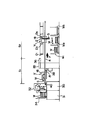
[Configuration of entire sorting device]
FIG. 1 is a plan view of the entire sorting apparatus, in which a monorail 4 is laid in an oblong shape to form a circulation type layout. On the monorail 4, a plurality of the sorting and transporting vehicles V are mounted. Each travels independently on the monorail 4 in the direction of transport F, sequentially goes from the loading station S1 to the sorting station S2 and the standby station S3, and returns to the loading station S1.
[0019]
The sorting station S2 is divided into a number of sorting positions in the transport F direction, and wagons W (W1, W2, W3,..., Wn,..., We) are arranged at the respective sorting positions. The
[0020]
At the entrance of the standby station S3, there is arranged a
[0021]
A work table 30 and a
[0022]
FIG. 2 is a schematic front view showing a part of the loading station S1 and a part of the sorting station S2. The work table 30 has a height at which the worker can easily transfer the mat M on the
[0023]
A retractable stopper (cylinder) 38 is disposed at the loading station S1 at a position rearward of the leader 35 in the direction of conveyance F from the leader 35. The
[0024]
[Action]
(1) In FIG. 2, the worker on the
[0025]
(2) When the worker turns on the
[0026]
(3) When the
[0027]
(4) When the
[0028]
(5) In FIG. 2, after the sorting and transporting vehicle V enters the sorting space S2, the
[0029]
(6) The sorting conveyance vehicle V after the drop supply continues to travel in the conveyance F direction, and proceeds to the standby station S3.
[0030]
(7) In the standby station S3, the
[0031]
(8) In FIG. 1, after the
[0032]
Each sorting transport vehicle V is started from the loading station S1 at intervals of, for example, 3 to 5 seconds, travels at the sorting station S2 at the same speed, and releases the mat M at the designated sorting position to reach the standby station S2.
[0033]
When a monorail is used as in this embodiment, the entire sorting apparatus can be made compact, and even if the curvature radius of the curve of the rail is narrowed, there is no difference between the inner and outer wheels, so that the smooth traveling of the transport vehicle can be achieved. Can be secured and the degree of freedom in rail layout is expanded.
[0034]
Further, when the sorting and transporting vehicle breaks down, only the transporting vehicle needs to be removed from the rail for repair, and it is not necessary to stop the entire sorting apparatus for a long time.
[0035]
Second Embodiment of the Invention
FIGS. 7 and 8 show an example in which a pair of
[0036]
In the sorting and transporting vehicle V, a plate-shaped
[0037]
The
[0038]
As shown in FIG. 9, the trigger
[0039]
The operation of the second embodiment is basically the same as that of the first embodiment, and is divided into the charging station S1, the sorting station S2, and the standby station S3 as described with reference to FIGS. 9 on a predetermined sorting position (sorting wagon W), the
[0040]
Other Embodiments of the Invention
(1) In the embodiment, as shown in FIG. 1, a magnet or a luminous body is used as the sorting position indicator D arranged at each sorting position, the sorting position indicator D is counted by the detector, and the sorting position signal is output to the sorting position signal. A method to recognize the specified sorting position by the corresponding count number is adopted, but an ID lip reader is mounted as a detector mounted on the sorting transport vehicle, and an ID chip is arranged as a sorting position indicator D and designated. It is also possible to release the mat when the ID chip of the sorting position marker D is recognized. In addition, various identification marks such as bar codes can be applied as the sorting position marks.
[0041]
(2) The sorting apparatus of FIG. 1 is used in a step of sorting dirty dust control products by type before cleaning processing, and is used in a step of picking a mat for each agent or customer after the cleaning processing, for example. It is also possible. Further, it can be used for sorting or picking mop for rental.
[0042]
(3) As a power supply for the drive device of the sorting and transporting vehicle, a battery can be mounted in addition to the method of supplying power from the rail as described above.
[0043]
(4) As the structure of the carrier, as shown in FIGS. 3 to 6 or FIGS. 7 and 8, in addition to the structure of rotating the carrier so as to open backward in the transport F direction, (A right angle direction). Further, the product release mechanism is not limited to the trigger type locking mechanism.
[0044]
【The invention's effect】
According to the present invention as described above,
(1) A rail is laid along a sorting station divided into a plurality of sorting positions, and a self-propelled sorting and transporting vehicle equipped with a driving device is mounted on the rail so as to be able to travel freely, and the sorting and transporting vehicle has a product release mechanism. Since it has a loading platform and a controller that controls the product release mechanism so that the dust control product is released at the sorting position corresponding to the input sorting position signal, it is possible to operate the sorting and transporting vehicle according to the amount of product input. It is not necessary to always drive the entire transport mechanism, even when the product input amount is small, as in the conventional chain, belt or roller type sorting and transporting device. This improves energy use efficiency and reduces operating costs. Can be.
[0045]
Further, even if a problem occurs in the sorting and transporting vehicle, it is only necessary to remove and repair the transporting vehicle alone, and it is not necessary to stop the entire transporting mechanism during the repair, and maintenance is easy.
[0046]
As a matter of course, labor and human rights costs can be reduced as compared with the conventional manual operation, and environmental health management can be facilitated.
[0047]
(2) An ID chip on which an individual identification code is written is attached to the dust control product, and a reader that reads the individual identification code of the ID chip of the dust control product, and a sorting position signal is self-propelled based on the individual identification code read by the reader. If a transmitting device for transmitting to the sorting and transporting vehicle is provided, the inspection and sorting can be performed reliably without the operator touching the hand. In particular, in the case of dust control products, by reducing opportunities for workers to touch the products, it is possible to reduce the deterioration of the working environment due to dust and mud coming out of the products, and it is also possible to reduce costs for environmental measures such as dustproof clothing.
[0048]
(3) If a monorail is laid as a rail and a straddle-type self-propelled sorting and transporting vehicle is mounted on the monorail, the entire sorting device can be compactly arranged, and there is no difference between the inner and outer wheels. Even if the radius of curvature of the rail is reduced, the sorting and transporting vehicle can keep running smoothly, and the degree of freedom in the layout of the rail is increased.
[0049]
(4) A pair of rails is laid along both sides of the sorting station as rails, and when a self-propelled sorting and transporting vehicle is placed on the pair of rails, heavy dust control products can be transported in a stable state. And can be sorted.
[Brief description of the drawings]
FIG. 1 is a plan view of a dust control product sorting apparatus to which the present invention is applied.
FIG. 2 is a schematic vertical sectional view of the vicinity of a charging station in FIG. 1;
FIG. 3 is a plan view of a monorail sorting and transporting vehicle.
FIG. 4 is a view taken in the direction of the arrow IV in FIG. 3;
FIG. 5 is a sectional view taken along line VV of FIG. 4;
FIG. 6 is an operation explanatory view showing a step of automatically returning the carrier to a horizontal posture.
FIG. 7 is a plan view of a four-wheel sorting and transporting vehicle that travels on a pair of rails according to another embodiment of the sorting and transporting vehicle.
FIG. 8 is a sectional view taken along line VIII-VIII of FIG. 7;
FIG. 9 is a sectional view taken along the line IX-IX of FIG. 7, showing an example of the trigger type locking mechanism.
[Explanation of symbols]
W Sorting wagon V Self-propelled sorting carrier D Sorting position marker 4
8 Electric motor (drive device)
10
18 Detector (detection device)
53 Electric motor (drive device)
51
57 detector (detection device)
Claims (4)
駆動装置を搭載した自走式仕分け搬送車を上記レールに走行自在に載せ、
仕分け搬送車は、製品放出機構を有する荷台と、入力された仕分け位置信号に対応する仕分け位置でダストコントロール製品を放出するように製品放出機構を制御するコントローラを備えていることを特徴とするダストコントロール製品の仕分け装置。Rails are laid along sorting stations divided into multiple sorting positions,
A self-propelled sorting and transporting vehicle equipped with a drive device is mounted on the rail so that it can travel freely,
A dust control product, comprising: a loading platform having a product release mechanism, and a controller that controls a product release mechanism to discharge a dust control product at a sorting position corresponding to an input sorting position signal. Sorting equipment.
ダストコントロール製品には、個体識別符号を書き込んだIDチップを取り付けてあり、
自走式仕分け搬送車の搬送経路に、ダストコントロール製品のIDチップの個体識別符号を読み取るリーダーと、該リーダーで読み取った個体識別符号に基づいて仕分け位置信号を自走式仕分け搬送車に発信する発信装置を配置してあることを特徴とするダストコントロール製品の仕分け装置。A dust control product sorting apparatus according to claim 1,
The dust control product has an ID chip with an individual identification code written on it,
A reader that reads the individual identification code of the ID chip of the dust control product on the transport path of the self-propelled sorting and transporting vehicle, and a transmission that transmits a sorting position signal to the self-propelled sorting and transporting vehicle based on the individual identification code read by the reader. Sorting device for dust control products, characterized in that the device is arranged.
レールとしてモノレールを敷設し、跨座型の自走式仕分け搬送車をモノレール上に載置していることを特徴とするダストコントロール製品の仕分け装置。The dust control product sorting apparatus according to claim 1 or 2,
A dust control product sorting device, characterized in that a monorail is laid as a rail and a straddle-type self-propelled sorting and transporting vehicle is mounted on the monorail.
レールとして仕分けステーションの両側に沿って一対のレールを敷設し、
自走式仕分け搬送車を上記一対のレール上に載置していることを特徴とするダストコントロール製品の仕分け装置。The dust control product sorting apparatus according to claim 1 or 2,
Laying a pair of rails along both sides of the sorting station as rails,
A sorting apparatus for dust control products, wherein a self-propelled sorting and transporting vehicle is mounted on the pair of rails.
Priority Applications (1)
| Application Number | Priority Date | Filing Date | Title |
|---|---|---|---|
| JP2002171496A JP2004018132A (en) | 2002-06-12 | 2002-06-12 | Sorting device for dust control product |
Applications Claiming Priority (1)
| Application Number | Priority Date | Filing Date | Title |
|---|---|---|---|
| JP2002171496A JP2004018132A (en) | 2002-06-12 | 2002-06-12 | Sorting device for dust control product |
Publications (1)
| Publication Number | Publication Date |
|---|---|
| JP2004018132A true JP2004018132A (en) | 2004-01-22 |
Family
ID=31171345
Family Applications (1)
| Application Number | Title | Priority Date | Filing Date |
|---|---|---|---|
| JP2002171496A Pending JP2004018132A (en) | 2002-06-12 | 2002-06-12 | Sorting device for dust control product |
Country Status (1)
| Country | Link |
|---|---|
| JP (1) | JP2004018132A (en) |
Cited By (6)
| Publication number | Priority date | Publication date | Assignee | Title |
|---|---|---|---|---|
| JP2010265066A (en) * | 2009-05-13 | 2010-11-25 | Duskin Co Ltd | Article sorter |
| JP2010275107A (en) * | 2009-06-01 | 2010-12-09 | Duskin Co Ltd | Article sorting device and sorted article management system |
| JP2010280459A (en) * | 2009-06-03 | 2010-12-16 | Duskin Co Ltd | Article sorting device |
| JP2016113291A (en) * | 2014-12-18 | 2016-06-23 | 株式会社Apt | Sorting device |
| JP2020111471A (en) * | 2017-09-30 | 2020-07-27 | ベイジン ギークプラス テクノロジー カンパニー リミテッド | Automatic commodity distribution sorting system and automatic commodity distribution sorting method |
| CN114506494A (en) * | 2020-11-16 | 2022-05-17 | 顺丰科技有限公司 | Package packing system and package packing method |
-
2002
- 2002-06-12 JP JP2002171496A patent/JP2004018132A/en active Pending
Cited By (6)
| Publication number | Priority date | Publication date | Assignee | Title |
|---|---|---|---|---|
| JP2010265066A (en) * | 2009-05-13 | 2010-11-25 | Duskin Co Ltd | Article sorter |
| JP2010275107A (en) * | 2009-06-01 | 2010-12-09 | Duskin Co Ltd | Article sorting device and sorted article management system |
| JP2010280459A (en) * | 2009-06-03 | 2010-12-16 | Duskin Co Ltd | Article sorting device |
| JP2016113291A (en) * | 2014-12-18 | 2016-06-23 | 株式会社Apt | Sorting device |
| JP2020111471A (en) * | 2017-09-30 | 2020-07-27 | ベイジン ギークプラス テクノロジー カンパニー リミテッド | Automatic commodity distribution sorting system and automatic commodity distribution sorting method |
| CN114506494A (en) * | 2020-11-16 | 2022-05-17 | 顺丰科技有限公司 | Package packing system and package packing method |
Similar Documents
| Publication | Publication Date | Title |
|---|---|---|
| JP7403516B2 (en) | Methods and equipment for sorting or retrieving items | |
| CN111278752B (en) | Moving carrier for use in a system and method for processing objects comprising a moving matrix carrier system | |
| US20220119210A1 (en) | Autonomous multi-tier racking and retrieval system for delivery vehicle | |
| JP2007533565A (en) | Equipment for conveying material rolls | |
| RU2391283C2 (en) | Roll transportation device | |
| JP2004018132A (en) | Sorting device for dust control product | |
| JP5557476B2 (en) | Article sorting apparatus and sorting article management system | |
| US7559738B2 (en) | Device and a method for switching pallets | |
| JP4045133B2 (en) | Mat sorter | |
| JP2636992B2 (en) | Garbage transport device | |
| JP5373475B2 (en) | Article sorting device | |
| JP3075780U (en) | Auto track equipment | |
| JP2660602B2 (en) | Automatic warehouse | |
| JP4100274B2 (en) | Picking equipment | |
| JP3094840B2 (en) | Sorting equipment | |
| JP5557477B2 (en) | Article sorting device | |
| CN212711022U (en) | Intelligent rail shuttling mother vehicle | |
| JP2002066849A (en) | Parts feeder and parts conveying line | |
| JP3779115B2 (en) | Automatic warehouse | |
| JP7083009B2 (en) | Wheel cleaning equipment and how to clean the wheels | |
| KR950000489B1 (en) | Parking system | |
| JP3561086B2 (en) | Automatic storage device | |
| CN114604590A (en) | Security check basket returning system and system control method | |
| CN114472184A (en) | Sorting equipment method and system in warehousing operation | |
| US4203370A (en) | In-floor towline automatic re-entry spur |
Legal Events
| Date | Code | Title | Description |
|---|---|---|---|
| A621 | Written request for application examination |
Free format text: JAPANESE INTERMEDIATE CODE: A621 Effective date: 20050511 |
|
| A977 | Report on retrieval |
Free format text: JAPANESE INTERMEDIATE CODE: A971007 Effective date: 20070709 |
|
| A131 | Notification of reasons for refusal |
Free format text: JAPANESE INTERMEDIATE CODE: A131 Effective date: 20070724 |
|
| A521 | Written amendment |
Free format text: JAPANESE INTERMEDIATE CODE: A523 Effective date: 20070919 |
|
| A02 | Decision of refusal |
Free format text: JAPANESE INTERMEDIATE CODE: A02 Effective date: 20071023 |