JP2004011732A - Side lip for bearing seal - Google Patents
Side lip for bearing seal Download PDFInfo
- Publication number
- JP2004011732A JP2004011732A JP2002165095A JP2002165095A JP2004011732A JP 2004011732 A JP2004011732 A JP 2004011732A JP 2002165095 A JP2002165095 A JP 2002165095A JP 2002165095 A JP2002165095 A JP 2002165095A JP 2004011732 A JP2004011732 A JP 2004011732A
- Authority
- JP
- Japan
- Prior art keywords
- side lip
- base
- tip
- seal
- continuous
- Prior art date
- Legal status (The legal status is an assumption and is not a legal conclusion. Google has not performed a legal analysis and makes no representation as to the accuracy of the status listed.)
- Pending
Links
Images


Classifications
-
- F—MECHANICAL ENGINEERING; LIGHTING; HEATING; WEAPONS; BLASTING
- F16—ENGINEERING ELEMENTS AND UNITS; GENERAL MEASURES FOR PRODUCING AND MAINTAINING EFFECTIVE FUNCTIONING OF MACHINES OR INSTALLATIONS; THERMAL INSULATION IN GENERAL
- F16C—SHAFTS; FLEXIBLE SHAFTS; ELEMENTS OR CRANKSHAFT MECHANISMS; ROTARY BODIES OTHER THAN GEARING ELEMENTS; BEARINGS
- F16C33/00—Parts of bearings; Special methods for making bearings or parts thereof
- F16C33/72—Sealings
- F16C33/76—Sealings of ball or roller bearings
- F16C33/78—Sealings of ball or roller bearings with a diaphragm, disc, or ring, with or without resilient members
- F16C33/7869—Sealings of ball or roller bearings with a diaphragm, disc, or ring, with or without resilient members mounted with a cylindrical portion to the inner surface of the outer race and having a radial portion extending inward
- F16C33/7879—Sealings of ball or roller bearings with a diaphragm, disc, or ring, with or without resilient members mounted with a cylindrical portion to the inner surface of the outer race and having a radial portion extending inward with a further sealing ring
- F16C33/7883—Sealings of ball or roller bearings with a diaphragm, disc, or ring, with or without resilient members mounted with a cylindrical portion to the inner surface of the outer race and having a radial portion extending inward with a further sealing ring mounted to the inner race and of generally L-shape, the two sealing rings defining a sealing with box-shaped cross-section
Landscapes
- Sealing With Elastic Sealing Lips (AREA)
- Sealing Of Bearings (AREA)
Abstract
Description
【0001】
【発明の属する技術分野】
この発明は、軸受シールのサイドリップに関するものである。
【0002】
【従来の技術】
従来の軸受シールのサイドリップ2は、図4に示すように、外周方向に拡径しており、その基部3の外周方向の屈曲面は、1つの半径r1の曲面を形成し、基部3および先端部4の厚みはほぼ同じか、または、先端部4の先端縁方向に薄くなっている。
【0003】
また、図5に示す従来のサイドリップ2aは、外周方向に拡径しており、その基部3aの外周方向の屈曲面は、半径r1の1つの曲面を形成し、基部3aの先端に続く先端部4aは、その外輪側の面が、基部3aの先端から順次膨出して先端部4aの中間へ厚みを増し、中間から先端方向へは順次厚みを減少している。
【0004】
図6に示す従来の軸受シールのサイドリップ2bは、外周方向に拡径しており、その基部3bの外周方向の屈曲面は、2つの半径r1、r2の曲面を形成し、基部3bおよび先端部4の厚みはほぼ同じか、または、先端部4の先端縁方向に薄くなっている。
【0005】
また、図7に示す従来のサイドリップ2cは、外周方向に拡径しており、その基部3cの外周方向の屈曲面は、半径r1、r2の2つの曲面を形成し、基部3cの先端に続く先端部4aは、その外輪側の面が、基部3cの先端から順次膨出して先端部4aの中間へ厚みを増し、中間から先端方向へは順次厚みを減少している。
【0006】
なお、前記半径r1とr2の曲面は、軸受シールの中心軸線を含む平面で断面した形状においては、曲線部を形成する。
【0007】
【発明が解決しようとする課題】
図4、図5に示す従来のサイドリップ2、2aは、図9(A)に示すとおり、軸受に装着すると、先端部4、4aの先端がスリンガー5に当接して押さえられ先端部4、4aが大きく湾曲し、軸方向シメシロ変動において、サイドリップ2、2aの先端の移動量Rが大きく、接触角度Q2が元の接触角度Q1より非常に小さくなり、接触面積が大きくなり、トルクが増加してシール寿命も短くなり、密封性が低下する。
なお、シメシロ量変化における先端部4、4aの接触角度の変化を詳細に比較した場合には、先端部4に比べて先端部4aの方が湾曲度合いは小さくなる。ただ、先端部4aは接触部である先端のゴム厚が中間部に比べて小さいため、接触部近傍で接触幅が増え、接触角Q2が小さくなる。
【0008】
図6および図7に示す従来のサイドリップ2b、2cは、基部3b、3cの外周方向の面が、2つの半径r1とr2の面の連続した曲面をなし、シールを軸受に装着してサイドリップ2b、2cの先端がスリンガー5で押されたときは、図9の(B)に示すように、サイドリップ2b、2cの先端部4、4aの下端に接する基部3b、3cの上部r1の部分で曲がり、スリンガー5への接触角度Q2が元の接触角度Q1に比べて大きく変化し、その接触角度Q2が小さくなるので、先端部4、4aのスリンガー5への接触面積が大きくなり、トルクが増加し、シール寿命も短くなり密封性が低下する。
【0009】
この発明は、サイドリップがスリンガーに当接してシメシロ変動した際に、スリンガーへの接触角度はあまり変わらず、従って、接触面積もあまり変わらず、かつ、先端の移動量も従来のものに比べて小さく、従って密封性能がよく、回転トルクが低く、寿命も長いサイドリップを提供することを目的とする。
【0010】
【課題を解決するための手段】
回転部を密封する軸受シールのサイドリップを、その基部が内周方向に傾斜して縮径形状となし、該基部に連続する先端部が外周方向に傾斜して拡径形状となし、前記軸受シールの中心軸線を含む平面で断面した形状において、前記基部は、シール本体との連続箇所の外周方向の部分と前記先端部との連続箇所の外周方向の部分は、同一または異なる2つの半径の曲線で構成し、かつ、これらの曲線間は直線で構成する。
【0011】
サイドリップの先端部は、その厚みが、基部の厚みよりも肉厚とする。
【0012】
シール本体と連続する基部の厚みが、該基部に連続する先端部の厚みよりも肉薄とする。
【0013】
【発明の実施の形態】
この発明の実施の形態を図面により説明する。
各図面におけるサイドリップは、軸受シールの中心軸線を含む平面で断面した形状を示す。
【0014】
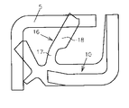
先ず図1に示すシールのサイドリップ12について説明する。
図中11の矢印はシールの外周方向を示す。
サイドリップ12は、シール本体10への付け根部分である基部13が、シールの内周方向へ傾斜した縮径形状をなし、それに連続した先端部14が、外周方向11へ傾斜した拡径形状をなす。
【0015】
そして、シール本体10の面から基部13および先端部14へ移行する外周方向の部分の、シール本体10から基部13への移行する部分は半径r3の曲線をなし、基部13から先端部14への移行する部分は半径r4の曲線をなし、半径r3と半径r4の曲線間は、直線部15を形成する。
先端部14の肉厚は、従来のサイドリップと同様に、先端まで同じ肉厚でも、先細りの肉厚でも、また、基部13より厚い肉厚であってもよい。
【0016】
基部13の内周方向の部分も、シール本体10から基部13への移行する部分と、基部13から先端部14への移行する部分は、曲線を形成し、2つの曲線間は直線部を形成するのが好ましい。
【0017】
図1に示すように、基部13のシール本体10に対する角度をα1とし、先端部14のシール本体10に対する角度をα2とする。
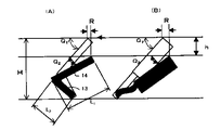
図8に示すように、シールを軸受に装着する前のサイドリップ12の高さをHとし、シメシロをhとする。
拡径部14の長さをL1とし、縮径部13の長さをL2とする。
各部分の関係は次の通りにするのが好ましい。
5°<α1<85°
5°<α2<85°
H<(L1+L2)<2H
【0018】
このサイドリップ12を備えたシール本体10を軸受に装置すると、先端部14の先端がスリンガー5に圧せられて、先端部14と基部13の接続部の外周側の半径r4の曲線部で曲がって先端部14は倒れ、基部13の中間が直線部15で、直線部15とシール本体10との付け根の外周方向側が半径r3の曲線部をなすので、基部13は先端部14に押されて付け根部の半径r3の曲線部でも曲がって内周方向に倒れ、基部13の角度α1が小さくなる。
すなわち、サイドリップ12は、図8(A)に示すとおり、基部13と先端部14の接続点と、基部13のシール本体10への付け根の点の2点で折れ曲がる。
【0019】
このような折れ曲がりにより、サイドリップ12の先端の外周方向への変移量Rは従来のサイドリップに比べて小さく、接触角度はあまり変わらず、従来のサイドリップの接触角度よりも大きく保持される。
【0020】
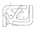
図2に示すサイドリップ16は、基部17と先端部18とからなり、基部17は従来のサイドリップのようにシール本体10に対して直立の円筒形状でも、または拡径形状でもよく、また、本件発明の先の実施の形態のサイドリップ12の基部13と同様のものでもよい。
先端部18は拡径形状をなし、その厚みは基部17の厚みよりも充分に大きい厚みである。
そして基部17の厚みは、少なくとも先端部近傍は先端部18に対して段部を形成して薄くなっている。
【0021】
図10において、シメシロ発生前のサイドリップ16の高さをHとし、先端部18の高さをHaとし、先端部18の厚みをW1とし、基部17の厚みをW2とすると各部の関係は次のとおりである。
1.2W2<W1<5.0W2
W1<Ha<H−W2
【0022】
サイドリップ16の先端部18は、基部17よりも肉厚が大きく、拡径形状、すなわち逆円錐形状をなすので、シメシロ変動に対し、図8(B)に示すように、サイドリップ16の変形は概ね基部17で吸収し、スリンガー5への接触角度はあまり変わらず、従って接触面積の増加を防止し、トルクの増加を防ぎ、高密封性を保持して寿命を長くする。
【0023】
図3に示すサイドリップ19は、基部20は図1に示すサイドリップ12の縮径部13と同様で、外周方向側の部分は、半径r3と半径r4の曲線と、この2つの曲線間は直線部15を形成する。
先端部21は、図2に示すサイドリップ16と同様に、その厚みは、基部20の厚みよりも急増した充分な厚みとするものである。
【0024】
サイドリップ19は、シメシロ発生時においては、図8の(A)で説明したように、2点屈折し、かつ、(B)で説明したように、先端部の湾曲を抑制しながら基部が屈曲するので、先端部19のスリンガー5への接触角度、接触面積がほとんど変わらず、トルクの増加を防ぎ、密封性を保持して寿命が長い。
【0025】
本件発明のサイドリップと従来のサイドリップとの接触荷重(緊迫力)の変化を比較したものを表1に示し、回転トルクの変化の比較したものを表2に示す。
【0026】
【表1】

【表2】
【発明の効果】
この発明に係るサイドリップは、スリンガーに当接してシメシロ変動した際に、スリンガーへの接触角度はあまり変わらず、従って、接触面積もあまり変わらず、かつ、先端の移動量も従来のものに比べて小さく、従ってトルクの増加を防ぎ、密封性能がよく、密封性を保持して寿命も長い。
【図面の簡単な説明】
【図1】本件発明係るサイドリップのシメシロ変化前の形状の説明図である。
【図2】他の実施の形態の本件発明係るサイドリップのシメシロ変化前の形状の説明図である。
【図3】他の実施の形態の本件発明係るサイドリップのシメシロ変化前の形状の説明図である。
【図4】従来例のサイドリップのシメシロ変化前の形状の説明図である。
【図5】他の従来例のサイドリップのシメシロ変化前の形状の説明図である。
【図6】他の従来例のサイドリップのシメシロ変化前の形状の説明図である。
【図7】他の従来例のサイドリップのシメシロ変化前の形状の説明図である。
【図8】本件発明に係るサイドリップのシメシロ変化状況の説明図である。
【図9】従来例のサイドリップのシメシロ変化状況の説明図である。
【図10】本件発明に係るサイドリップの構造の説明図である。
【符号の説明】
1 シール本体
2 サイドリップ
3 基部
4 先端部
5 スリンガー
10 シール本体
11 外周方向
12 サイドリップ
13 基部
14 先端部
15 直線部
16 サイドリップ
17 基部
18 先端部
19 サイドリップ
20 基部
21 先端部
R 移動量
r 湾曲半径
Q1,Q,α1,α2角度
H,Ha 高さ
W1,W2厚み
L1,L2長さ[0001]
TECHNICAL FIELD OF THE INVENTION
The present invention relates to a side lip of a bearing seal.
[0002]
[Prior art]
As shown in FIG. 4, the
[0003]
Further, the conventional side lip 2a shown in FIG. 5 is increased in diameter toward the outer circumference, the outer circumference of the bending surface of the
[0004]
The
[0005]
In addition, the
[0006]
The curved surfaces of the radii r 1 and r 2 form a curved portion in a cross section taken on a plane including the central axis of the bearing seal.
[0007]
[Problems to be solved by the invention]
When the
In addition, when the change in the contact angle of the
[0008]
[0009]
According to the present invention, when the side lip abuts on the slinger and fluctuates, the contact angle to the slinger does not change much, and therefore, the contact area does not change much, and the moving amount of the tip is compared to the conventional one. It is an object of the present invention to provide a side lip which is small and therefore has good sealing performance, low rotational torque and long life.
[0010]
[Means for Solving the Problems]
The bearing has a side lip for sealing a rotating part, the base of which is inclined in an inner peripheral direction to form a reduced diameter shape, and a leading end continuous with the base is inclined to an outer peripheral direction to form an enlarged diameter shape. In a cross-sectional shape including a plane including the center axis of the seal, the base has a portion in an outer peripheral direction of a continuous portion with the seal body and a portion in an outer peripheral direction of a continuous portion with the tip portion having the same or different two radii. It is constituted by curves, and between these curves is constituted by a straight line.
[0011]
The tip of the side lip is thicker than the base.
[0012]
The thickness of the base continuous with the seal body is made thinner than the thickness of the distal end continuous with the base.
[0013]
BEST MODE FOR CARRYING OUT THE INVENTION
An embodiment of the present invention will be described with reference to the drawings.
The side lip in each drawing shows a cross-sectional shape on a plane including the central axis of the bearing seal.
[0014]
First, the
The
The
[0015]
The portion of the outer circumferential direction that transitions from the surface of the
Like the conventional side lip, the
[0016]
Also in the inner circumferential portion of the
[0017]
As shown in FIG. 1, the angle relative to the
As shown in FIG. 8, the height of the
The length of the enlarged
It is preferable that the relationship between the parts is as follows.
5 ° <α 1 <85 °
5 ° <α 2 <85 °
H <(L 1 + L 2 ) <2H
[0018]
When the
That is, as shown in FIG. 8A, the
[0019]
Due to such bending, the amount of displacement R of the tip of the
[0020]
The
The
The thickness of the
[0021]
10, the height of the Interference occurs before the
1.2W 2 <W 1 <5.0W 2
W 1 <Ha <H−W 2
[0022]
Since the
[0023]
The
Like the
[0024]
The
[0025]
Table 1 shows a change in contact load (tensing force) between the side lip of the present invention and a conventional side lip, and Table 2 shows a change in rotational torque.
[0026]
[Table 1]
[Table 2]
【The invention's effect】
When the side lip according to the present invention abuts on the slinger and fluctuates, the contact angle with the slinger does not change much, and therefore the contact area does not change much, and the moving amount of the tip is smaller than that of the conventional one. Small, thus preventing an increase in torque, having good sealing performance, maintaining sealing performance, and having a long life.
[Brief description of the drawings]
FIG. 1 is an explanatory diagram of a shape of a side lip according to the present invention before a change in shrinkage.
FIG. 2 is an explanatory diagram of a shape of a side lip according to another embodiment of the present invention before a change in shrinkage.
FIG. 3 is an explanatory diagram of a shape of a side lip according to another embodiment of the present invention before a change in shrinkage.
FIG. 4 is an explanatory diagram of a shape of a conventional side lip before a change in shrinkage.
FIG. 5 is an explanatory diagram of a shape of a side lip of another conventional example before a change in shrinkage.
FIG. 6 is an explanatory view of a shape of a side lip of another conventional example before a change in shrinkage.
FIG. 7 is an explanatory diagram of a shape of a side lip of another conventional example before a change in shrinkage.
FIG. 8 is an explanatory diagram of a change state of the side lip according to the present invention.
FIG. 9 is an explanatory diagram of a change state of a side lip of a conventional example.
FIG. 10 is an explanatory view of a structure of a side lip according to the present invention.
[Explanation of symbols]
DESCRIPTION OF
Claims (3)
Priority Applications (1)
| Application Number | Priority Date | Filing Date | Title |
|---|---|---|---|
| JP2002165095A JP2004011732A (en) | 2002-06-06 | 2002-06-06 | Side lip for bearing seal |
Applications Claiming Priority (1)
| Application Number | Priority Date | Filing Date | Title |
|---|---|---|---|
| JP2002165095A JP2004011732A (en) | 2002-06-06 | 2002-06-06 | Side lip for bearing seal |
Publications (1)
| Publication Number | Publication Date |
|---|---|
| JP2004011732A true JP2004011732A (en) | 2004-01-15 |
Family
ID=30433017
Family Applications (1)
| Application Number | Title | Priority Date | Filing Date |
|---|---|---|---|
| JP2002165095A Pending JP2004011732A (en) | 2002-06-06 | 2002-06-06 | Side lip for bearing seal |
Country Status (1)
| Country | Link |
|---|---|
| JP (1) | JP2004011732A (en) |
Cited By (6)
| Publication number | Priority date | Publication date | Assignee | Title |
|---|---|---|---|---|
| JP2005291450A (en) * | 2004-04-02 | 2005-10-20 | Nsk Ltd | Seal ring and rolling bearing unit with seal ring |
| JP2006161917A (en) * | 2004-12-06 | 2006-06-22 | Koyo Sealing Techno Co Ltd | Sealing device |
| WO2009145178A1 (en) | 2008-05-27 | 2009-12-03 | 株式会社ジェイテクト | Sealing device for rolling bearing |
| CN105042082A (en) * | 2015-07-07 | 2015-11-11 | 青岛睿辰密封科技有限公司 | Self-sealing full-polytetrafluoroethylene oil seal with monitoring function |
| WO2020080408A1 (en) * | 2018-10-18 | 2020-04-23 | Nok株式会社 | Sealing device |
| EP3653912A1 (en) | 2018-11-13 | 2020-05-20 | Nakanishi Metal Works Co., Ltd. | Rotary seal |
-
2002
- 2002-06-06 JP JP2002165095A patent/JP2004011732A/en active Pending
Cited By (9)
| Publication number | Priority date | Publication date | Assignee | Title |
|---|---|---|---|---|
| JP2005291450A (en) * | 2004-04-02 | 2005-10-20 | Nsk Ltd | Seal ring and rolling bearing unit with seal ring |
| JP2006161917A (en) * | 2004-12-06 | 2006-06-22 | Koyo Sealing Techno Co Ltd | Sealing device |
| WO2009145178A1 (en) | 2008-05-27 | 2009-12-03 | 株式会社ジェイテクト | Sealing device for rolling bearing |
| US8585296B2 (en) | 2008-05-27 | 2013-11-19 | Jtekt Corporation | Rolling bearing sealing device |
| CN105042082A (en) * | 2015-07-07 | 2015-11-11 | 青岛睿辰密封科技有限公司 | Self-sealing full-polytetrafluoroethylene oil seal with monitoring function |
| WO2020080408A1 (en) * | 2018-10-18 | 2020-04-23 | Nok株式会社 | Sealing device |
| CN111527334A (en) * | 2018-10-18 | 2020-08-11 | Nok株式会社 | Sealing device |
| EP3653912A1 (en) | 2018-11-13 | 2020-05-20 | Nakanishi Metal Works Co., Ltd. | Rotary seal |
| US11009076B2 (en) | 2018-11-13 | 2021-05-18 | Nakanishi Metal Works Co., Ltd. | Rotary seal |
Similar Documents
| Publication | Publication Date | Title |
|---|---|---|
| JP3740219B2 (en) | Rolling bearing sealing device | |
| US7575519B2 (en) | Boot for a joint | |
| JP2006342827A (en) | Sealing device | |
| JPWO2007049429A1 (en) | Universal joint boots | |
| JP2004011732A (en) | Side lip for bearing seal | |
| JP4189648B2 (en) | Constant velocity joint boots | |
| JPH08109966A (en) | Boot | |
| JP2003004063A (en) | Boot for constant velocity joint | |
| JP4546655B2 (en) | CVJ boots | |
| JP2020079619A (en) | Rotary seal | |
| JP4240217B2 (en) | Sealing device | |
| JP4250951B2 (en) | Sealing device | |
| JPH11311338A (en) | Oil seal | |
| JP3157854U (en) | Oil seal | |
| JP3869058B2 (en) | Oil seal | |
| JP3017737U (en) | Oil seal for both rotations | |
| JPH0746838Y2 (en) | Oil seal | |
| JP2553435Y2 (en) | Oil seal with rib | |
| WO2005119106A1 (en) | Seal structure and cross shaft coupling | |
| JP3821931B2 (en) | Sealing device | |
| JP2006266412A (en) | Constant velocity universal joint and boots for constant velocity universal joint | |
| JP3707705B2 (en) | Oil seal | |
| JP2003090439A (en) | Sealing device | |
| JPH09112703A (en) | Oil seal | |
| JP2000179701A (en) | Sealing device |
Legal Events
| Date | Code | Title | Description |
|---|---|---|---|
| A977 | Report on retrieval |
Free format text: JAPANESE INTERMEDIATE CODE: A971007 Effective date: 20050829 |
|
| A131 | Notification of reasons for refusal |
Free format text: JAPANESE INTERMEDIATE CODE: A131 Effective date: 20050906 |
|
| A521 | Written amendment |
Free format text: JAPANESE INTERMEDIATE CODE: A523 Effective date: 20051102 |
|
| A02 | Decision of refusal |
Free format text: JAPANESE INTERMEDIATE CODE: A02 Effective date: 20060627 |
|
| A521 | Written amendment |
Free format text: JAPANESE INTERMEDIATE CODE: A523 Effective date: 20060726 |
|
| A521 | Written amendment |
Free format text: JAPANESE INTERMEDIATE CODE: A821 Effective date: 20060726 |
|
| A911 | Transfer of reconsideration by examiner before appeal (zenchi) |
Free format text: JAPANESE INTERMEDIATE CODE: A911 Effective date: 20060831 |
|
| A912 | Removal of reconsideration by examiner before appeal (zenchi) |
Free format text: JAPANESE INTERMEDIATE CODE: A912 Effective date: 20061215 |
|
| A521 | Written amendment |
Free format text: JAPANESE INTERMEDIATE CODE: A523 Effective date: 20080509 |
|
| A521 | Written amendment |
Free format text: JAPANESE INTERMEDIATE CODE: A821 Effective date: 20080509 |