JP2004008670A - Washer-dryer - Google Patents
Washer-dryer Download PDFInfo
- Publication number
- JP2004008670A JP2004008670A JP2002169711A JP2002169711A JP2004008670A JP 2004008670 A JP2004008670 A JP 2004008670A JP 2002169711 A JP2002169711 A JP 2002169711A JP 2002169711 A JP2002169711 A JP 2002169711A JP 2004008670 A JP2004008670 A JP 2004008670A
- Authority
- JP
- Japan
- Prior art keywords
- water
- drying
- drum
- cloth quality
- cloth
- Prior art date
- Legal status (The legal status is an assumption and is not a legal conclusion. Google has not performed a legal analysis and makes no representation as to the accuracy of the status listed.)
- Pending
Links
Images


Abstract
Description
【0001】
【発明が属する技術分野】
本発明は、乾燥工程を備えた乾燥洗濯機に関するものである。
【0002】
【従来の技術】
近年、生活の合理化が進む中、消費者のニーズに答える商品として、洗濯から乾燥までを自動に運転できるドラム式乾燥洗濯機が普及し始めている。しかし、乾燥性能の向上に向けて、克服すべき課題として、乾燥ムラを無くし、過乾燥による布傷みを解消することがあげられる。ドラム式乾燥洗濯機は、ドラムが水槽内で水平軸を中心に回転する構造が主流となっており、洗濯から乾燥までを同一のドラムで行う事ができるため、洗濯,脱水から乾燥までの機能を兼ね備えたドラム式乾燥洗濯機の代表的なものとなっている。
【0003】
この従来のドラム式乾燥洗濯機(特開平8−80396号)の概略の構成及び動作を以下に説明する。図21は、従来のドラム式乾燥洗濯機の一例を示す概略斜視図であり、図22は同じく概略側面断面図である。これらの図に示すように、ドラム式乾燥洗濯機は、主として、外箱1の内側にバネで吊り下げられた水槽4と、この水槽4の内側で水平軸を中心に回転するように配されたドラム5との二重構造となっている。
【0004】
水槽4は、運転中の振動を吸収するためにバネで吊り下げられているものであり、また、洗濯液や脱水液を貯え、且つ排出する機能を有している。ドラム5の周壁全体には、洗濯時の給水,脱水時の排水,及び乾燥時の温風を通過させるために、多数の小孔5cが設けられている。水槽4の上部には乾燥用ヒータ28が取り付けられており、さらに、乾燥時に温風を循環させるための送風ファン25が設けられている。
【0005】
乾燥洗濯機の正面には洗濯物を出し入れするための開閉扉3が設けられており、この開閉扉3を閉じて水槽4との間のドアパッキン10を挟み込む事により、水槽4の洗濯物投入口を密閉する構造となっている。
【0006】
また、図において、9はドラム5を回転させるための駆動装置、18は洗濯液等を機外に排出するための排水ポンプ、17aは水槽4と排水ポンプ18との間の配管経路に設けられた糸屑フィルタである。なお、この乾燥洗濯機の正面上部には操作パネル11が設けられている。
【0007】
上記のような構成を備えたドラム式乾燥洗濯機においては、制御回路の制御動作により、通常はドラム5内に洗濯物を収容したままの状態で、洗い→すすぎ→脱水→乾燥の順で全ての工程を連続的に実行することができ、また、それぞれの工程を独立して実行することも可能である。
【0008】
洗い工程から乾燥工程に至るまでの動作は、図23のフローチャートに示すように、ドラム5内に洗濯物を入れ、電源スイッチをON(ステップS1)し、コース選定を行なう。次に、スタート・一時停止スイッチを押(ON)(ステップS2)し、ドラム5を回転させて、容量をモータートルクの変動値によって検知(ステップS3)し、検知された布量をマイクロコンピューター(以下、マイコンと称する)により記憶する。
【0009】
そして、給水弁13を開けて水槽4内に給水(ステップS4)し、水位センサー23にて所定水位を検知すると、短時間のタンブリングを行って洗濯物に水を含ませる。洗濯物に水を含ませることで水槽4内の水が所定水位よりも減水するため、その減水した水位を水位センサー23にて検知して、所定水位から減水した水位までの水位変化量をマイコンに記憶し、再び短時間のタンブリングを行い、さらに減水した水位を水位センサー23にて検知して、1回目にタンブリングをさせて減水した水位から2回目にタンブリングをさせて減水した水位までの水位変化量を記憶する。そして、2回の水位変化量と布量検知の結果から洗濯物の布質の判定(ステップS5)を行い、洗い工程へと移行する。
【0010】
洗い工程は、ドラム5を低速回転させることにより行われる(ステップS6)。その後、排水ポンプ18をONして排水される(ステップS7)。その後、再び水槽4内に給水を行い、すすぎ工程が行われる(ステップS8)。
【0011】
すすぎ工程は、洗剤を含まない洗濯水を洗濯物に含ませ、駆動装置9にてドラム5を低速回転させて、ドラム5内の洗濯物をタンブリングすることで行われる。その後、排水ポンプ18をONして洗濯水を機外へ排水し(ステップS9)、洗濯物の脱水工程が行われる(ステップS10)。
【0012】
脱水工程は、駆動装置9にてドラム5を高速回転させて洗濯物に含まれていた水は、ドラム5の小孔5cから飛ばし、水槽4の内面を伝ってその下部に導き、排水ポンプ18により機外に強制的に排水される。
【0013】
続いて乾燥工程に移行し、ステップS11に進んで、上記ステップS5において判定された洗濯物の布質を呼び出し、ステップS12に進んで、洗濯物の布質は親水性繊維かそれとも疎水性繊維か否かマイコンにて判定し、乾燥工程が行なわれる。
【0014】
乾燥工程は、乾燥用ヒータ7にて加熱されて高温になった空気を送風機8によりドラム5内に吹き込みながら、駆動装置9にてドラム5を低速回転させて行われる。乾燥工程時に洗濯物から蒸発した水分は、縦方向に配設された冷却器33の内部で冷却水と接触することにより除去される。該冷却水は、ドラム5から排出される温風と接触し、温風内に含まれる細かな糸屑を捕集して、水槽4の下部で接続される排水経路を経て排水ポンプ18にて機外へ排水され、乾燥運転時間が経過すると乾燥工程が終了する。
【0015】
洗濯物の布質が親水性繊維であると判定されれば、ステップS13に進んで、基準乾燥運転時間Tに補正時間cを加えて乾燥運転時間を長めに設定し、乾燥工程が行われ、乾燥運転時間が経過すると、乾燥工程が終了する。
【0016】
ステップS12において、洗濯物の布質が疎水性繊維であると判定されればステップS14に進んで、基準乾燥運転時間Tから補正時間dを差し引いて乾燥運転時間を短めに設定し、上記と同様に乾燥工程が行われ、乾燥運転時間が経過すれば乾燥工程が終了する。
【0017】
【発明が解決しようとする課題】
ところで、上記のような構成は、布質や布量の判定の結果により設定運転時間を増減させる方法であるが、送風量やヒータ熱量が一定であるため、化繊布など熱に弱い洗濯物の布傷みが生じる。
【0018】
また、布質や布量の違いによって生ずる蒸発水量の違いに対応して、設定運転時間を増減させる方法では、乾燥性能を最大限に引き出せてはおらず、最適な乾燥時間を得ることが出来ないという問題点があった。
【0019】
本発明は、上記に鑑み、洗濯物を布質に応じて乾燥させることができる乾燥洗濯機の提供を目的としている。また、本発明の別の目的は、水分を含んだ温風を除湿する冷却器に供給する冷却水量を最適にして、無駄な水の消費を抑えることができる乾燥洗濯機を提供するところにある。
【0020】
【課題を解決させる為の手段】
上記目的を達成するため、本発明は、布質を判別する布質判別手段と、この布質判別結果から乾燥運転の運転条件を変える運転制御手段とを備えた乾燥洗濯機を特徴としている。
【0021】
上記構成によれば、吸水性に優れた布質であるか否かを判別し、布質に応じて乾燥運転条件を変えることにより、化繊布などの熱に弱い布を洗濯・乾燥する場合と、比較的熱にも強い綿などを洗濯・乾燥する場合とで、熱風の熱量を変えることが可能となり、布種に応じた熱量で乾燥させ、布傷みを防止することができる。
【0022】
乾燥運転制御対象は、ドラムに温風を供給するヒータ及び送風ファンからなる温風供給手段や、ドラムから排出された水分を含んだ温風を冷却水で冷却して除湿する冷却器が挙げられる。
【0023】
これら制御対象の制御方法としては、制御対象が送風ファンの場合には、その回転数を変えることで、布種に応じた熱風の風量で乾燥させることが可能となり、布傷みを抑えることができる。具体的には、吸水性に優れた布質であると判定したときには、送風ファンの回転数を上げることで風量を増加させ、また、吸水性に優れていないと判定したときには、送風ファンの回転数を下げることで風量を減少させる制御を行う。
【0024】
制御対象がヒータの場合には、その入力電圧を変えることで、布種に応じた熱量で乾燥させることが可能となる。具体的には、吸水性に優れた布質であると判定したときに、ヒータ入力電圧を上げることで熱量を増加させ、また、吸水性に優れていないと判定したときに、その判定に応じて、ヒータ入力の電圧を減少させ、熱量を調節する制御を行う。
【0025】
制御対象が冷却器の場合には、洗濯物の容量を判定する容量判定手段を設け、その容量判定結果に応じて冷却器の冷却水量を変化させることで、容量によって変化する蒸発水量に応じた冷却水量で乾燥させ、最適な乾燥時間で運転を終了することができる。具体的には、容量が多いと判定されたときに、冷却器における冷却水量を増加させ、容量が少ないと判定されたときに、冷却水量を減少させる制御を行う。
【0026】
制御対象が冷却器の場合、布質判別手段による布質判別結果に応じて冷却水量を変化させる制御も可能である。具体的には、吸水性に優れた布質であると判定されたときには、冷却器における冷却水量を増加させ、また、吸水性に優れていないと判定されたときには、冷却器における冷却水量を減少させる制御を行う。
【0027】
なお、布質判別手段は、給水時間の差から布質を判別する手法、および給水量の差から布質を判別する手法のいずれをも採用可能である。この給水時間及び給水量は、設定水位に到達するまでの給水時間あるいは給水量をいうが、この設定水位とは、洗濯物の容量判別により演算された水位であるのが好ましいが、これに限らず、容量に関係なく予め定められた水位であってもよい。
【0028】
例えば、洗濯工程から乾燥工程までの連続運転が設定されている場合に、洗濯前の容量センシングによって設定された水位に到達するまでの給水時間に基づいて、乾燥工程での冷却器への冷却水の供給水量を変えることで、布種によって変化する蒸発水量に応じた冷却水量で乾燥させることで、最適な乾燥時間で運転を終了することができる。
【0029】
【発明の実施形態】
以下、この発明の実施形態の構造を図面に基づいて説明する。なお、図1から図5に示すドラム式乾燥洗濯機の基本構成は以下の各実施形態について共通するものであるため、第1の実施形態において、その基本構成を説明し、第2の実施形態以降においては、その説明を省略する。
【0030】
<第1の実施形態>
図1は本発明によるドラム式乾燥洗濯機を示す概略斜視図である。ドラム式乾燥洗濯機は、底台2の上に外箱が配され、外箱1の上面が天板32で覆われている。外箱1は化粧鋼板を折曲して形成されている。天板32は圧縮ボード等から成り、外箱1にネジ止めされている。
【0031】
外箱1の前面上部には、使用者が操作を行なう操作パネル11が取付けられている。図2に示すように、操作パネル11は、表示部11aと複数の操作キー111〜119とを有し、背面に制御回路31(図3参照)が配されている。表示部11aは液晶表示装置から成り、入力情報等を表示する。
【0032】
操作キー111〜119はドラム式乾燥洗濯機に設けられた運転条件を設定する操作等を行なう。電源キー111はドラム式乾燥洗濯機の電源をON/OFFする。電源キー111をONすると、表示部11aには「標準コース」の洗濯乾燥条件が表示される。標準コースは木綿や化繊等の洗濯物の場合に洗濯工程及び乾燥工程を最適に行なう条件が予め設定されている。使用者はコース切替キー114を押下することにより、後述する「ドライコース」「毛布コース」等の運転条件を選択することができる。
【0033】
洗濯キー116を押下すると、洗い工程、すすぎ工程及び脱水工程から成る洗濯工程のみを行なって、乾燥工程を行なわないように設定することができる。乾燥キー115を押下すると、乾燥工程のみを行なうように設定される。洗いキー117、すすぎキー118又は脱水キー119を押下すると、それぞれ洗い工程、すすぎ工程、脱水工程のみを行なうように設定される。
【0034】
運転条件が設定されると、スタートキー112をONすることによりドラム式乾燥洗濯機の運転が開始される。運転中にスタートキー112を押下すると、ドラム式乾燥洗濯機の運転が一時停止され、再度押下すると運転が再開される。一時停止中にドアロック解除キー113を押下すると、開閉扉3のロック状態が解除され、洗濯物の追加投入ができるようになっている。
【0035】
図3はドラム式乾燥洗濯機の側面断面図である。制御回路31は、ドラム式乾燥洗濯機の運転を制御する制御プログラムが格納され、操作キー111〜119により運転条件が設定されると、それに基づいてドラム式乾燥洗濯機の運転が行なわれる。
【0036】
外箱1の内部には前面に向かって開口した開口部4aを有する水槽4が後方へ行くほど下がるように傾斜して配されている。水槽4内には開口部5aを有して回転するドラム5が同軸に傾斜して配されている。この傾斜によって前面側からのドラム5内の見通しをよくしている。
【0037】
水槽4の底部外面には駆動機構9が取付けられている。駆動機構9はケース9a内にロータ9bとステータ9cとから成るモータを内装している。ステータ9cはケース9aに固定され、ロータ9bはドラム5の槽軸5dに固定されている。槽軸5dはケース9aに固定されたベアリング6によって支持され、一端がドラム5に固定されているためドラム5が回転自在になっている。これにより、ドラム5に直結された駆動機構9が構成され、ロータ9bの回転が直接ドラム5を回転駆動する。また、ロータ9bの回転数を検知する回転検知手段(不図示)が設けられており、駆動機構9は、回転検知手段の検知結果に基づいて回転速度が制御されるインバータモータになっている。
【0038】
ドラム5の周壁には小孔5cが設けられている。小孔5cは水槽4とドラム5とを連通させており、水槽4とドラム5との間を洗濯水が流出入できるようになっている。ドラム5の内壁面にはバッフル5bが突出して形成され、ドラム5の回転により洗濯物を引っかけて持上げ、洗濯液中に落下させることにより洗浄が行なわれるようになっている。バッフル5bはドラム5の内壁に固定されるか、あるいはドラム5と一体に形成される。
【0039】
ドラム5の開口部5aの外周縁には液体バランサー5eが設けられている。流体バランサー5eは塩水等の比重の大きい液体が封入されており、ドラム5の回転時に該流体が移動して洗濯物及び洗濯水の片寄りによる重心移動を打消すようになっている。液体バランサー5eはドラム5の内周縁に設けてもよい。
【0040】
洗濯物投入口1aと水槽4の開口部4aの周縁にはゴムや軟質樹脂等の弾性体から成るパッキン10が取付けられ、洗濯物を出し入れするアクセス路を形成する。開閉扉3には、パッキン10と密着する窓部3aが突設されている。開閉扉3の前面の一部及び窓部3aはドラム5内を視認できるようにガラス等に透明部材で形成されている。
【0041】
パッキン10は開閉扉3を閉じたときに内周縁10aが窓部3aの周縁に密着してアクセス路を閉口する。これにより、水槽4内の洗濯水が外部へ漏水しないようになっている。また、パッキン10には蛇腹等が設けられ、水槽4の揺動に応じてたわみを生じて追従するようになっている。
【0042】
外箱1内の上部には洗剤を収容する洗剤ケース15が配されている。洗剤ケース15内には洗剤の収納部を通る通路と通らない通路とが設けられ、洗剤ケース15に流入する洗濯水が切り替えて流通できるようになっている。洗剤ケース15から一方には給水パイプ12が導出され、他方にはドアパッキン10に支持された給水ノズル15aが導出されている。給水パイプ12は給水弁13に接続されている。
【0043】
図4は給水弁13の詳細図である。図に示すように、給水弁13は、吐出口13a、13bと流入口13cとを有している。流入口13cは水道管に接続され、市水を供給できるようになっている。吐出口13aは給水パイプ12に接続され、給水弁13の駆動により市水を吐出し、洗濯水が洗剤ケース15を介して給水ノズル15aから水槽4内に給水される。給水弁13の吐出口13bは、後述するように、温風が循環する乾燥用ダクト27(図5参照)に接続され、温風内の水分を凝縮する。
【0044】
図3において、水槽4の底面には流出口4cから排水ダクト16が導出されている。排水ダクト16aは糸屑フィルタ17aを内装した接続ケース17と水槽4との間を接続し、排水ダクト16bは接続ケース17と排水ポンプ18の間を接続している。排水ダクト16cは外部と連通し、排水ポンプ18の動作により洗濯水を外部へ排水するようになっている。
【0045】
糸屑フィルタ17aは、例えば、格子状に形成された樹脂あるいは、袋状に形成された目の細かい繊維等から成り、洗濯水が通過することによって洗濯水中の糸屑等を集積するようになっている。また、糸屑フィルタ17aは接続ケース17内に着脱自在に装着され、外箱1の前面下部からキャップ17bとともに取り外して容易に清掃できるようになっている。
【0046】
排水ダクト16aから分岐するエアートラップ21には、導圧パイプ22が導出されている。水位センサー23は導圧パイプ22及びエアートラップ21を介して水槽4と連通し、水槽4内の水圧による圧力(水圧)が水位センサー23に伝えられる。水位センサー23は、コイルと磁性体とを内装し、水槽4内の水位による圧力変化に応じて磁性体がコイル内を移動する。そして、コイル内の磁性体の位置により生じるコイルのインダクタンスを発振周波数として検出し、水槽4内の水位を検出するようになっている。水位センサー23は水槽4内と連通するどの位置に設けてもよい。
【0047】
図5はドラム式乾燥洗濯機の一部異なる部分を切断した側面断面図である。図5に示すように、水槽4の上方には洗濯物を乾燥するために送風ファン25及びヒータ28から構成された温風ユニット(温風供給手段)24が設けられている。この温風ユニット24は、水槽4の開口部4aに臨む吹出し口4bと水槽4の下部に設けられた循環口4dとを連結する乾燥用ダクト27の経路途中に配されている。
【0048】
乾燥用ダクト27は、図5に示すように、水槽4の外側において、水槽4の下部に設けられた循環口4dから冷却室33を通り、送風ファン25及びヒータ28からなる温風ユニット24を経て吹出し口4bに至る一連の経路である。この乾燥用ダクト27と水槽4との間で温風が以下のように循環する。すなわち、乾燥運転時にのみ送風ファン25によってヒータ28で熱せられた空気は、吹出し口4bからドラム5内に吹き込まれ、衣類の水分を十分に吸収してドラム5の小孔5cから水槽4の循環口4dを通り、乾燥用ダクト27に入って冷却室33に流れる。冷却室33では給水弁13の吐出口13bから噴霧された冷却水により、温風が冷却されて水分が凝縮し、この水分の除去された空気が再び送風ファン25によって吹出し口4bに流れ、温風が水槽4と乾燥用ダクト27との間で循環するようになっている。
【0049】
ヒータ28は、乾燥用ダクト27に取付けられた温度センサー29a、29bの検出温度に応じて出力が制御され、所定の温度をドラム5内に送出するようになっている。また、前述したように、給水弁13の吐出口13bは乾燥用ダクト27の経路途中に設けられた冷却室(冷却器)64に接続され、給水弁13の駆動により乾燥用ダクト27を通る温風内の水分を冷却して凝縮するようになっている。
【0050】
図6は制御ブロック図を示す。制御動作の中心となるのは、マイクロコンピュータ50(以下マイコンと称す)である。マイコン50には、操作キー111〜119、水位検知手段としての水位センサー23、電源回路51、リセット回路52、モータ9の回転検知手段53、ヒータ28の温度検知手段54からの信号が入力される。
【0051】
マイコン50内には、衣類の負荷容量を判定する容量判定手段55と、洗濯物の布質を判別する布質判別手段56と、洗い・すすぎ・脱水・乾燥を順次移行して運転制御する運転制御手段57と、容量判定により決定した工程時間を見張るタイマー58と、乾燥工程の運転終了を検知する乾燥終了検知手段59とを備えている。
【0052】
容量判定手段55は、例えば、ドラムを回転させるモータ9のトルク変動値を例えば、マグネット及びリードスイッチからなる回転検知手段53によって検知し、その信号を入力して容量を判定する。
【0053】
布質判別手段56は、水位センサー23とタイマー58とにより、容量判定による設定水位到達までの給水時間の差によって判別する。例えば、洗い工程開始前に検出した容量判定により給水を開始し、設定水位に到達するまでの給水時間によって布質を判定する。この際、単純に給水しただけでは、衣類全体に吸水させることができないために、衣類に吸水させることを目的とする、なじませ攪拌を行う。なじませ攪拌は、給水中、あるいは給水完了後に低速でドラムを回転させることで、布質(吸水性)を正確に判定することが可能となる。例えば、給水を開始後、ドラム4を45rpmで右回転させ、20秒回転させた後、3秒間の停止を挟んで、同様に左回転させる。これを繰り返して設定水位に到達するまでの時間をタイマー58で判定し、布質の検知を行う。このように、なじませ攪拌を行えば、布質の違いによる給水時間、あるいは給水量を正確に算出できると共に、容量が多い場合やかさばった衣類など、全体に水が浸透し難い場合においても、正確に布質の判定を可能とする。
【0054】
マイコン50の出力側には、マイコン50で判定された状態により、負荷駆動回路60にて各負荷の動作を行い、モータ9、(乾燥用)給水弁13・13b、ヒータ28、送風ファン25、排水ポンプ18等を動作させ、洗濯・すすぎ・脱水・乾燥と順次移行して運転制御する。また、この運転内容を表示する表示部11aや、終了時及びエラー時等に使用者に知らせるためにブザー61を制御する。
【0055】
次に、本実施形態の動作制御を図7に示すフローチャートにより説明する。洗濯物投入口1aより洗濯物を投入して開閉扉3を閉じると、開閉扉3の窓部3aの周縁にパッキン10の内周縁10aが密着して水槽4が封止される。そして、操作キーの電源入/切111を押し(ステップ1−1)、スタート/一時停止112を押す(ステップ1−2)と、負荷容量を判定するための容量センシング(ステップ1−3)がスタートする。
【0056】
容量センシングにより負荷容量が判定されると、容量にあった水位が設定され、運転時間を表示部11aに表示し、ドラム5内に給水(ステップ1−4)が開始される。このとき、マイコン50により、給水時間を算出し、布質を判定する(ステップ1−5)。綿などの吸水性に優れた布では給水時間が長くなり、化繊などの吸水性に優れていない布では給水時間が短くなる。
【0057】
洗い工程は、ドラム5を低速回転させることにより行われる(ステップ1−6)。その後、排水ポンプ18をONして排水される(ステップ1−7)。その後、再び水槽内4に給水を行い(ステップ1−8)、すすぎ工程が行われる(ステップ1−9)。
【0058】
すすぎ工程は、洗剤を含まない洗濯水を洗濯物に含ませ、駆動装置9にてドラム5を低速回転させて、ドラム5内の洗濯物をタンブリングすることで行われる。その後、排水ポンプ18をONして洗濯水を機外へ排水し(ステップ1−10)、洗濯物の脱水工程が行われる(ステップ1−11)。
【0059】
脱水工程は、駆動装置9にてドラム5を高速回転させて洗濯物に含まれていた水は、ドラム3の小孔5cから飛ばし、水槽4の内面を伝ってその下部に導き、排水ポンプ18により機外に強制的に排水される。続いて、乾燥工程に移行し、上記ステップ1−5において算出された給水時間を呼び出し(ステップ1−12)、マイコン50により送風ファンの回転数を判定し(ステップ1−13)、乾燥工程が行なわれる。
【0060】
図14に示すように、給水時間が長い場合にはファン回転数を増加させ、給水時間が短い場合にはファン回転数を減少させ、風量の調節を行なう(ステップ1−14、15、16、17)。例えば、容量判定が2〜3kg(テーブル左C欄)で、設定水位までに到達する時間が100秒以上(給水時間a)要したならば、送風ファン回転数を5000rpm(テーブル右a欄)で運転する。
【0061】
乾燥工程は、乾燥用ヒータ28にて加熱されて高温になった空気を送風ファン25によりドラム5内に吹き込みながら、駆動装置9にてドラム5を低速回転させて行われる。
【0062】
乾燥工程時に洗濯物から蒸発した水分は、縦方向に配設された冷却器33の内部で冷却水と接触することにより除去される。該冷却水は、ドラム5から排出される温風と接触し、温風内に含まれる細かな糸屑を捕集して、水槽4の下部で接続される排水経路を経て排水ポンプ18にて機外へ排水されて、マイコン50によって乾燥運転の終了判定が成されると乾燥工程が終了する。
【0063】
このように、本実施形態では、容量判定により設定水位に到達するまでの給水時間から布質を判別し、その判別結果に応じて送風ファンの回転数を変化させて、風量調節を行っているので、布傷みを防止することができる。
【0064】
<第2の実施形態>
図8は第2の実施形態を示すフローチャートである。なお、図1〜図6に示す全自動乾燥洗濯機の構造、及び衣類の投入から容量センシングの工程は第1の実施形態と同一であるため説明は省略する。
【0065】
本実施形態では、布質判別手段は、水位センサー23とタイマー58とにより、容量判定による設定水位到達までの給水量によって判別する。例えば、洗い工程開始前に検出した容量判定により容量にあった水位を設定し、給水を開始し、その後、再び容量センシングを行い、その増加容量を計算して給水量を算出することで、布質を判定する。これ以外に、給水完了までの間でなじませ攪拌を行いながら行ってもよい。
【0066】
本実施形態の制御動作は、容量センシング(ステップ2−3)により負荷容量が判定されると、容量にあった水位が設定され、運転時間を表示部11aに表示し、ドラム5内に給水(ステップ2―4)が開始される。この後、再び容量センシングを行い、マイコン50によりステップ2−3からの増加容量を計算し、給水量を算出することで、布質を判定する(ステップ2−5)。
【0067】
綿などの吸水性に優れた布では給水量が多くなり、化繊などの吸水性に優れていない布では給水量が少なくなる。また、洗い工程から脱水工程は上記第1の実施形態と同一であるため説明は省略する。
【0068】
脱水工程(ステップ2−11)が終了すると、乾燥工程に移行し、マイコン50によって算出された(ステップ2−5)給水量を呼び出し(ステップ2−12)、マイコン50により送風ファン25の回転数を判定し(ステップ2−13)、乾燥工程が行なわれる。
【0069】
図15に示すように、給水量が多い場合にはファン回転数を増加させ、給水量が少ない場合にはファン回転数を減少させ、風量の調節を行なう(ステップ2−14、15、16、17)。例えば、容量判定が2〜3kg(テーブル左C欄)で、給水量が12〜14リットル(L)要したならば、送風ファン回転数を4000rpm(テーブル右c欄)で運転する。なお、上記以外の乾燥工程に関する説明は、第1の実施形態と同一であるため省略する。
【0070】
このように、本実施形態では、容量判定により設定水位に到達するまでの給水量から布質を判別し、その判別結果に応じて送風ファンの回転数を変化させて、風量調節を行っているので、布傷みを防止することができる。
【0071】
<第3の実施形態>
図9は第3の実施形態を示すフローチャートである。なお、図1〜図6に示す全自動乾燥洗濯機の構造、及び衣類の投入から脱水工程は第1の実施形態と同一であるため説明は省略する。
【0072】
本実施形態では、布質の判別を第1の実施形態と同様に、容量判定により設定された水位に到達するまでの給水時間から行っている。また、制御対象は、ヒータの入力電圧としている。
【0073】
本実施形態における制御動作は、脱水工程(ステップ3−11)が終了すると、乾燥工程に移行し、マイコン50によって算出された(ステップ3−5)給水時間を呼び出し(ステップ3−12)、マイコン50によりヒータ28の入力電圧を判定し(ステップ3−13)、乾燥工程が行なわれる。
【0074】
図16に示すように、給水量が多い場合にはヒータ28の入力電圧を増加させ、給水量が少ない場合にはヒータ28の入力電圧を減少させ、熱量の調節を行なう(ステップ3−14、15、16、17)。例えば、容量判定が1〜2kg(テーブル左B欄)で、設定水位までに到達する給水時間が60〜70秒(給水時間c)要したならば、ヒータ入力電圧は90V(テーブル右c欄)で運転する。なお、上記以外の乾燥工程に関する説明は、第1の実施形態と同一であるため省略する。
【0075】
このように、本実施形態では、容量判定により設定水位に到達するまでの給水時間から布質を判別し、その判別結果に応じてヒータの入力電圧を変化させて、熱量調節を行っているので、布傷みを防止することができる。
【0076】
<第4の実施形態>
図10は第4の実施形態を示すフローチャートである。なお、図1〜図6に示す全自動乾燥洗濯機の構造、及び衣類の投入から脱水工程は第2の実施形態と同一であるため説明は省略する。
【0077】
本実施形態では、布質判別手段は、第2の実施形態と同様に、容量判定による設定水位到達までの給水量によって判別する。また、制御対象は第3の実施形態と同様なヒータの入力電圧である。
【0078】
本実施形態における制御動作は、脱水工程(ステップ4−11)が終了すると、乾燥工程に移行し、マイコン50によって算出された(ステップ4−5)給水量を呼び出し(4−12)、マイコン50によりヒータ28の入力電圧を判定し(ステップ4−13)、乾燥工程が行なわれる。
【0079】
図17に示すように、給水量が多い場合にはヒータ28の入力電圧を増加させ、給水量が少ない場合にはヒータ28の入力電圧を減少させ、熱量の調節を行なう(ステップ4−14、15、16、17)。例えば、容量判定が3〜4kg(テーブル左D欄)で、給水量が15リットル(L)未満ならば、ヒータの入力電圧を80V(テーブル右d欄)に設定して運転する。上記以外の乾燥工程に関する説明は、第1の実施形態と同一であるため省略する。
【0080】
このように、本実施形態では、容量判定により設定水位に到達するまでの給水量から布質を判別し、その判別結果に応じてヒータの入力電圧を変化させて、熱量調節を行っているので、布傷みを防止することができる。
【0081】
<第5の実施形態>
図11は第5の実施形態を示すフローチャートである。なお、図1〜図6に示す全自動乾燥洗濯機の構造、及び衣類の投入から容量センシングの工程は第1の実施形態と同一であるため説明は省略する。
【0082】
本実施形態では、容量判定に応じて乾燥用の冷却器の冷却水量を変更するものである。容量判定手段の構成は上記第1の実施形態と同様である。
【0083】
本実施形態の制御動作は、容量センシング(ステップ5−3)により負荷容量が判定されると、容量にあった水位が設定され、運転時間を表示部11aに表示し、ドラム5内に給水(ステップ5―4)が開始される。また、洗い工程から脱水工程は第1の実施形態と同一であるため説明は省略する。
【0084】
脱水工程(ステップ5−10)が終了すると、乾燥工程に移行し、上記ステップ5−3において判定された負荷容量を呼び出し(ステップ5−11)、マイコン50により冷却器64における乾燥用給水弁13の吐出口13bの開閉制御を行ない、冷却水量を調節し(ステップ5−12)、乾燥工程が行なわれる。
【0085】
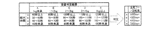
図18に示すように、負荷容量が多い場合には冷却水量を増加させ、負荷容量が少ない場合には冷却水量を減少させ、水量の調節を行なう(ステップ5−13、14、15、16)。例えば、容量判定が2.5〜4kg(テーブル左b欄)のとき、乾燥用冷却水量を0.35リットル(L)/分に設定して運転する。上記以外の乾燥工程に関する説明は、第1の実施形態と同一であるため省略する。
【0086】
このように、本実施形態では、容量判定により冷却器の冷却水量を調節することで、容量の大小によって生じる蒸発水量の違いに対応した冷却水量を供給することができ、無駄な水の消費を抑えることができる。
【0087】
<第6の実施形態>
図12は第6の実施形態を示すフローチャートである。なお、図1〜図6に示す全自動乾燥洗濯機の構造、及び衣類の投入から脱水工程は第1の実施形態と同一であるため説明は省略する。
【0088】
本実施形態では、容量判定による設定水位到達までの給水時間によって布質を判別し、その布質判別に応じて制御対象である冷却器の冷却水量を変更するものである。
【0089】
本実施形態の制御動作は、脱水工程(ステップ6−11)が終了すると、乾燥工程に移行し、マイコン50によって算出された(ステップ6−5)給水時間を呼び出し(ステップ6−12)、マイコン50により冷却器における乾燥用給水弁の吐出口13bの開閉制御を行い、冷却水量を調節し(ステップ6−13)、乾燥工程が行なわれる。
【0090】
図19に示すように、給水時間が長い場合には冷却水量を増加させ、給水時間が短い場合には冷却水量を減少させ、水量の調節を行なう(ステップ6−14、15、16、17)。例えば、容量判定が4kg以上(テーブル左E欄)で、給水時間が100秒未満ならば、乾燥用冷却水量を0.25リットル(L)/分に設定して供給運転する。上記以外の乾燥工程に関する説明は、第1の実施形態と同一であるため省略する。
【0091】
このように、本実施形態では、容量判定により設定水位に到達するまでの給水時間から布質を判別し、その判別結果に応じて冷却器の冷却水量を調節することで、布種の違いによって生じる蒸発水量の違いに対応した冷却水量を供給することができ、無駄な水の消費を抑えることができる。
【0092】
<第7の実施形態>
図13は第7の実施形態を示すフローチャートである。なお、図1〜図6に示す全自動乾燥洗濯機の構造、及び衣類の投入から脱水工程は第2の実施形態と同一であるため説明は省略する。
【0093】
本実施形態では、容量判定による設定水位到達までの給水量によって布質を判別し、その布質判別に応じて制御対象である冷却器の冷却水量を変更するものである。
【0094】
本実施形態の制御動作は、脱水工程(ステップ7−11)が終了すると、乾燥工程に移行し、マイコン50によって算出された(ステップ7−5)給水量を呼び出し(ステップ7−12)、マイコン50により冷却器における乾燥用給水弁13の開閉制御を行い、冷却水量を調節し(ステップ7−13)、乾燥工程が行なわれる。
【0095】
図20に示すように、給水量が多い場合には冷却水量を増加させ、給水量が少ない場合には冷却水量を減少させ、水量の調節を行なう(ステップ7−14、15、16、17)。例えば、容量判定が1kg未満(テーブル左A欄)で、給水量が8〜10リットル(L)ならば、乾燥用冷却水量を0.35リットル(L)/分に設定して供給運転する。なお、上記以外の乾燥工程に関する説明は、第1の実施形態と同一であるため省略する。
【0096】
このように、本実施形態では、容量判定により設定水位に到達するまでの給水量から布質を判別し、その判別結果に応じて冷却器の冷却水量を調節することで、布種の違いによって生じる蒸発水量の違いに対応した冷却水量を供給することができ、無駄な水の消費を抑えることができる。
【0097】
なお、本発明は、上記実施形態に限定されるものではなく、本発明の範囲内で修正・変更を加えることができるのは勿論である。例えば、上記実施形態では洗濯から乾燥まで自動運転できる横型のドラム式乾燥洗濯機について説明したが、これに限るものではなく、縦型乾燥洗濯機に本発明を適用してもよいことは勿論である。
【0098】
【発明の効果】
以上の説明から明らかな通り、本発明によると、吸水性に優れた布質であるか否かを判別し、布質に応じて乾燥運転条件を変えることにより、化繊布などの熱に弱い布を洗濯・乾燥する場合と、比較的熱にも強い綿などを洗濯・乾燥する場合とで、熱風の熱量を変えることが可能となり、布種に応じた熱量で乾燥させ、布傷みを防止することができる。
【0099】
また、布量、布質に応じて、冷却器への冷却水量を変更することにより、吸水性の異なる布種の違いによって生ずる蒸発水量の違いに対応した冷却水量を供給することでき、最適な乾燥時間で乾燥を終了させることができると共に、無駄な水の消費も抑えることができる。
【図面の簡単な説明】
【図1】本発明の実施形態におけるドラム式乾燥洗濯機の外部構造を示す概略斜視図
【図2】図1の操作部の詳細図
【図3】図1のドラム式乾燥洗濯機の内部構造を示す概略側面断面図
【図4】図3の給水周りの詳細図
【図5】図1のドラム式乾燥洗濯機の一部異なる部分を切断した側面断面図
【図6】図1の制御部のブロック図
【図7】第1実施形態の運転プログラムフローチャート
【図8】本発明の第2実施形態の運転プログラムフローチャート
【図9】本発明の第3実施形態の運転プログラムフローチャート
【図10】本発明の第4実施形態の運転プログラムフローチャート
【図11】本発明の第5実施形態の運転プログラムフローチャート
【図12】本発明の第6実施形態の運転プログラムフローチャート
【図13】本発明の第7実施形態の運転プログラムフローチャート
【図14】本発明の第1の実施形態の運転プログラムテーブル
【図15】本発明の第2の実施形態の運転プログラムテーブル
【図16】本発明の第3の実施形態の運転プログラムテーブル
【図17】本発明の第4の実施形態の運転プログラムテーブル
【図18】本発明の第5の実施形態の運転プログラムテーブル
【図19】本発明の第6の実施形態の運転プログラムテーブル
【図20】本発明の第7の実施形態の運転プログラムテーブル
【図21】従来のドラム式乾燥洗濯機の概略斜視図
【図22】従来のドラム式乾燥洗濯機の概略側面断面図
【図23】従来のドラム式乾燥洗濯機の運転プログラムフローチャート
【符号の説明】
1:外箱
1a:洗濯物投入口
2:底台
3:開閉扉
4:水槽
5:ドラム
5b:バッフル
5c:小孔
9:駆動装置
10:パッキン
11:操作パネル
11a:表示部
12:給水パイプ
13:給水弁
13b:乾燥用給水弁
15:洗剤ケース
16:排水ダクト
17a:糸屑フィルタ
17:接続ケース
18:排水ポンプ
23:水位センサー
24:温風ユニット
25:送風ファン
27:乾燥用ダクト
28:ヒータ
29a:温度センサー
31:制御装置
32:天板
33:冷却室[0001]
TECHNICAL FIELD OF THE INVENTION
TECHNICAL FIELD The present invention relates to a washing machine having a drying step.
[0002]
[Prior art]
2. Description of the Related Art In recent years, with the streamlining of life, drum-type drying and washing machines that can automatically operate from washing to drying have begun to spread as products that respond to consumer needs. However, to improve drying performance, problems to be overcome include eliminating uneven drying and eliminating damage to the cloth due to overdrying. Drum-type washing machines have a structure in which the drum rotates around a horizontal axis in a water tub, and the washing and drying can be performed by the same drum. It has become a typical drum-type drying and washing machine that has both.
[0003]
The general configuration and operation of this conventional drum type washing machine (Japanese Patent Laid-Open No. 8-80396) will be described below. FIG. 21 is a schematic perspective view showing an example of a conventional drum type washing machine, and FIG. 22 is a schematic side sectional view of the same. As shown in these figures, the drum-type drying and washing machine is mainly provided with a
[0004]
The
[0005]
An opening / closing
[0006]
In the figure, 9 is a driving device for rotating the
[0007]
In the drum-type drying washing machine having the above-described configuration, the control operation of the control circuit normally allows washing, rinsing, dehydrating, and drying in the order of washing, rinsing, dehydrating, and drying while the laundry is stored in the
[0008]
In the operation from the washing step to the drying step, as shown in the flowchart of FIG. 23, the laundry is put in the
[0009]
Then, the
[0010]
The washing process is performed by rotating the
[0011]
The rinsing step is performed by causing washing water not containing detergent to be contained in the laundry, rotating the
[0012]
In the dehydration step, the water contained in the laundry is rotated by high speed rotation of the
[0013]
Subsequently, the process proceeds to a drying step, proceeds to step S11, calls the laundry fabric determined in step S5, proceeds to step S12, and determines whether the laundry fabric is hydrophilic fiber or hydrophobic fiber. It is determined by the microcomputer whether or not the drying process is performed.
[0014]
The drying step is performed by rotating the
[0015]
If the cloth of the laundry is determined to be hydrophilic fiber, the process proceeds to step S13, the correction operation time c is added to the reference drying operation time T, the drying operation time is set longer, and the drying step is performed. After the elapse of the drying operation time, the drying process ends.
[0016]
If it is determined in step S12 that the laundry fabric is a hydrophobic fiber, the process proceeds to step S14, in which the drying operation time is set shorter by subtracting the correction time d from the reference drying operation time T. After the drying operation time has elapsed, the drying step is completed.
[0017]
[Problems to be solved by the invention]
By the way, the above-described configuration is a method of increasing or decreasing the set operation time according to the result of the determination of the cloth quality or the cloth amount. Fabric damage occurs.
[0018]
In addition, in the method of increasing or decreasing the set operation time in response to the difference in the amount of evaporative water caused by the difference in the cloth quality and the cloth amount, the drying performance cannot be maximized, and the optimum drying time cannot be obtained. There was a problem.
[0019]
SUMMARY OF THE INVENTION In view of the above, an object of the present invention is to provide a drying washing machine capable of drying laundry according to cloth quality. Another object of the present invention is to provide a washing machine capable of optimizing an amount of cooling water supplied to a cooler for dehumidifying hot air containing moisture and suppressing wasteful water consumption. .
[0020]
[Means for solving the problem]
In order to achieve the above object, the present invention is characterized by a drying and washing machine provided with a cloth quality discriminating means for discriminating the cloth quality and an operation control means for changing an operation condition of a drying operation from the result of the cloth quality discrimination.
[0021]
According to the above configuration, it is determined whether or not the cloth is excellent in water absorbency, and by changing the drying operation conditions according to the cloth, washing and drying a heat-sensitive cloth such as a synthetic fiber cloth. The amount of heat of the hot air can be changed between when washing and drying cotton or the like which is relatively resistant to heat, and drying can be performed with the amount of heat according to the type of cloth, thereby preventing damage to the cloth.
[0022]
The drying operation control target includes hot air supply means including a heater for supplying hot air to the drum and a blower fan, and a cooler for cooling and dehumidifying hot air containing moisture discharged from the drum with cooling water. .
[0023]
As a control method of these control objects, when the control object is a blower fan, by changing the number of revolutions, it is possible to dry the hot air flow according to the cloth type, and to suppress damage to the cloth. . Specifically, when it is determined that the fabric is excellent in water absorbency, the air volume is increased by increasing the rotation speed of the blower fan, and when it is determined that the cloth is not excellent in water absorbency, the rotation of the blower fan is increased. Control is performed to reduce the air volume by reducing the number.
[0024]
When the object to be controlled is a heater, by changing the input voltage, it is possible to dry with a calorific value according to the type of cloth. Specifically, when it is determined that the fabric is excellent in water absorbency, the amount of heat is increased by increasing the heater input voltage, and when it is determined that the fabric is not excellent in water absorbency, the determination is made in accordance with the determination. Thus, control is performed to reduce the voltage of the heater input and adjust the amount of heat.
[0025]
When the control target is a cooler, a capacity determining unit that determines the capacity of the laundry is provided, and the amount of cooling water of the cooler is changed in accordance with the result of the capacity determination, so that the amount of evaporative water that varies with the capacity is changed. Drying is performed with the amount of cooling water, and the operation can be completed in an optimal drying time. Specifically, control is performed to increase the amount of cooling water in the cooler when it is determined that the capacity is large, and to decrease the amount of cooling water when it is determined that the capacity is small.
[0026]
When the control target is a cooler, it is also possible to control to change the amount of cooling water according to the cloth quality determination result by the cloth quality determination means. Specifically, when it is determined that the fabric is excellent in water absorption, the amount of cooling water in the cooler is increased, and when it is determined that the cloth is not excellent in water absorption, the amount of cooling water in the cooler is decreased. Is performed.
[0027]
Note that the cloth quality determining means may employ either a method of determining the cloth quality from a difference in water supply time or a method of determining the cloth quality from a difference in water supply amount. The water supply time and the water supply amount refer to a water supply time or a water supply amount until the set water level is reached, and the set water level is preferably a water level calculated by the capacity determination of the laundry, but is not limited thereto. Instead, the water level may be a predetermined water level regardless of the capacity.
[0028]
For example, when continuous operation from the washing process to the drying process is set, based on the water supply time until the water level set by the capacity sensing before washing is reached, the cooling water to the cooler in the drying process is determined. By changing the amount of supplied water, drying can be performed with an optimal drying time by drying with a cooling water amount corresponding to the amount of evaporative water that varies depending on the type of cloth.
[0029]
DETAILED DESCRIPTION OF THE INVENTION
Hereinafter, a structure of an embodiment of the present invention will be described with reference to the drawings. Since the basic configuration of the drum-type drying and washing machine shown in FIGS. 1 to 5 is common to the following embodiments, the basic configuration will be described in the first embodiment, and the second embodiment will be described. Hereinafter, the description thereof will be omitted.
[0030]
<First embodiment>
FIG. 1 is a schematic perspective view showing a drum type washing and washing machine according to the present invention. In the drum type washing machine, an outer box is disposed on the
[0031]
An
[0032]
The
[0033]
When the
[0034]
When the operating conditions are set, the operation of the drum type washing machine is started by turning on the
[0035]
FIG. 3 is a side sectional view of the drum type washing machine. The
[0036]
Inside the
[0037]
A
[0038]
A
[0039]
A
[0040]
A packing 10 made of an elastic material such as rubber or soft resin is attached to the periphery of the
[0041]
When the opening /
[0042]
A
[0043]
FIG. 4 is a detailed view of the
[0044]
In FIG. 3, a
[0045]
The
[0046]
A
[0047]
FIG. 5 is a side sectional view in which a part different from the drum type washing machine is cut. As shown in FIG. 5, a hot air unit (hot air supply means) 24 including a
[0048]
As shown in FIG. 5, the drying
[0049]
The output of the
[0050]
FIG. 6 shows a control block diagram. The main part of the control operation is a microcomputer 50 (hereinafter, referred to as a microcomputer). Signals from the
[0051]
In the
[0052]
The
[0053]
The cloth quality determination means 56 determines the difference between the water supply time until the set water level is reached by the capacity determination using the
[0054]
On the output side of the
[0055]
Next, the operation control of the present embodiment will be described with reference to the flowchart shown in FIG. When the laundry is thrown in from the
[0056]
When the load capacity is determined by the capacity sensing, a water level corresponding to the capacity is set, the operation time is displayed on the
[0057]
The washing process is performed by rotating the
[0058]
The rinsing step is performed by causing washing water not containing detergent to be contained in the laundry, rotating the
[0059]
In the spin-drying step, the
[0060]
As shown in FIG. 14, when the water supply time is long, the fan rotation speed is increased, and when the water supply time is short, the fan rotation speed is decreased to adjust the air volume (steps 1-14, 15, 16, 16). 17). For example, if the capacity determination is 2-3 kg (table left column C) and the time to reach the set water level is 100 seconds or more (water supply time a), the fan speed is set to 5000 rpm (table right column a). drive.
[0061]
The drying step is performed by rotating the
[0062]
Moisture evaporated from the laundry during the drying process is removed by contacting the cooling water inside the cooler 33 disposed vertically. The cooling water comes into contact with the warm air discharged from the
[0063]
As described above, in the present embodiment, the cloth quality is determined from the water supply time until the set water level is reached by the capacity determination, and the rotation speed of the blower fan is changed according to the determination result to adjust the air volume. Therefore, damage to the cloth can be prevented.
[0064]
<Second embodiment>
FIG. 8 is a flowchart showing the second embodiment. Since the structure of the fully automatic washing machine shown in FIGS. 1 to 6 and the steps from the loading of the clothes to the sensing of the capacity are the same as those in the first embodiment, the description will be omitted.
[0065]
In the present embodiment, the cloth quality determination means determines the water level by the
[0066]
In the control operation of the present embodiment, when the load capacity is determined by the capacity sensing (step 2-3), a water level corresponding to the capacity is set, the operation time is displayed on the
[0067]
A cloth having excellent water absorbency such as cotton requires a large amount of water supply, and a cloth having excellent water absorbency such as synthetic fiber requires a small amount of water supply. In addition, the steps from the washing step to the dehydrating step are the same as those in the first embodiment, and a description thereof will be omitted.
[0068]
When the dehydration step (Step 2-11) is completed, the process proceeds to the drying step, where the water supply amount calculated by the microcomputer 50 (Step 2-5) is called (Step 2-12), and the rotation number of the
[0069]
As shown in FIG. 15, when the amount of water supply is large, the fan speed is increased, and when the amount of water supply is small, the fan speed is decreased to adjust the air volume (steps 2-14, 15, 16, 17). For example, if the capacity is determined to be 2 to 3 kg (column C on the left side of the table) and the amount of supplied water is required to be 12 to 14 liters (L), the operation is performed at 4000 rpm (column c on the right side of the table). Note that the description of the drying process other than the above is the same as that of the first embodiment, and a description thereof will be omitted.
[0070]
As described above, in the present embodiment, the cloth quality is determined from the amount of water supplied until the set water level is reached by the capacity determination, and the number of revolutions of the blower fan is changed according to the determination result to adjust the air volume. Therefore, damage to the cloth can be prevented.
[0071]
<Third embodiment>
FIG. 9 is a flowchart showing the third embodiment. Note that the structure of the fully automatic washing machine shown in FIGS. 1 to 6 and the steps from the loading of clothes to the dewatering process are the same as those in the first embodiment, and a description thereof will be omitted.
[0072]
In the present embodiment, the determination of the fabric quality is performed from the water supply time until the water reaches the water level set by the capacity determination, as in the first embodiment. The control target is the input voltage of the heater.
[0073]
When the dehydration step (step 3-11) ends, the control operation according to the present embodiment shifts to the drying step, and calls the water supply time calculated by the microcomputer 50 (step 3-5) (step 3-12). The input voltage of the
[0074]
As shown in FIG. 16, when the amount of water supply is large, the input voltage of the
[0075]
As described above, in the present embodiment, the amount of water is determined from the water supply time until the set water level is reached by the capacity determination, and the amount of heat is adjusted by changing the input voltage of the heater according to the determination result. In addition, damage to the cloth can be prevented.
[0076]
<Fourth embodiment>
FIG. 10 is a flowchart showing the fourth embodiment. The structure of the fully automatic washing machine shown in FIGS. 1 to 6 and the steps from the loading of the clothes to the dewatering process are the same as those in the second embodiment, and a description thereof will be omitted.
[0077]
In the present embodiment, as in the second embodiment, the cloth quality determining means determines based on the amount of water supplied until the set water level is reached by the capacity determination. The control target is the same input voltage of the heater as in the third embodiment.
[0078]
When the dehydration step (step 4-11) ends, the control operation according to the present embodiment shifts to the drying step and calls the water supply amount calculated by the microcomputer 50 (step 4-5) (4-12). To determine the input voltage of the heater 28 (step 4-13), and the drying step is performed.
[0079]
As shown in FIG. 17, when the amount of water supply is large, the input voltage of the
[0080]
As described above, in the present embodiment, since the cloth quality is determined from the amount of water supplied until the set water level is reached by the capacity determination, and the input voltage of the heater is changed in accordance with the determination result, the heat amount is adjusted. In addition, damage to the cloth can be prevented.
[0081]
<Fifth embodiment>
FIG. 11 is a flowchart showing the fifth embodiment. Since the structure of the fully automatic washing machine shown in FIGS. 1 to 6 and the steps from the loading of the clothes to the sensing of the capacity are the same as those in the first embodiment, the description will be omitted.
[0082]
In the present embodiment, the cooling water amount of the drying cooler is changed according to the capacity determination. The configuration of the capacity determining means is the same as that of the first embodiment.
[0083]
In the control operation of the present embodiment, when the load capacity is determined by the capacity sensing (step 5-3), the water level corresponding to the capacity is set, the operation time is displayed on the
[0084]
When the dehydration step (Step 5-10) is completed, the process proceeds to the drying step, the load capacity determined in Step 5-3 is called up (Step 5-11), and the
[0085]
As shown in FIG. 18, when the load capacity is large, the cooling water amount is increased, and when the load capacity is small, the cooling water amount is decreased to adjust the water amount (steps 5-13, 14, 15, 16). . For example, when the capacity is determined to be 2.5 to 4 kg (left column b in the table), the operation is performed with the cooling water amount for drying set to 0.35 liter (L) / min. The description of the drying process other than the above is the same as that of the first embodiment, and thus will be omitted.
[0086]
As described above, in the present embodiment, by adjusting the cooling water amount of the cooler based on the capacity determination, it is possible to supply the cooling water amount corresponding to the difference in the amount of evaporating water caused by the magnitude of the capacity, thereby reducing wasteful water consumption. Can be suppressed.
[0087]
<Sixth embodiment>
FIG. 12 is a flowchart showing the sixth embodiment. Note that the structure of the fully automatic washing machine shown in FIGS. 1 to 6 and the steps from the loading of clothes to the dewatering process are the same as those in the first embodiment, and a description thereof will be omitted.
[0088]
In the present embodiment, the cloth quality is determined based on the water supply time until the set water level is reached by the capacity determination, and the cooling water amount of the cooler to be controlled is changed according to the cloth quality determination.
[0089]
In the control operation of the present embodiment, when the dehydration step (step 6-11) is completed, the process proceeds to the drying step, and the water supply time calculated by the microcomputer 50 (step 6-5) is called (step 6-12). The opening / closing control of the
[0090]
As shown in FIG. 19, when the water supply time is long, the amount of cooling water is increased, and when the water supply time is short, the amount of cooling water is reduced to adjust the water amount (steps 6-14, 15, 16, 17). . For example, if the capacity determination is 4 kg or more (E column on the left of the table) and the water supply time is less than 100 seconds, the supply operation is performed with the cooling water amount for drying set to 0.25 liter (L) / min. The description of the drying process other than the above is the same as that of the first embodiment, and thus will be omitted.
[0091]
As described above, in the present embodiment, the cloth quality is determined from the water supply time until the set water level is reached by the capacity determination, and the cooling water amount of the cooler is adjusted according to the determination result, so that the cloth type is different. It is possible to supply a cooling water amount corresponding to a difference in the generated evaporating water amount, and it is possible to suppress wasteful water consumption.
[0092]
<Seventh embodiment>
FIG. 13 is a flowchart showing the seventh embodiment. The structure of the fully automatic washing machine shown in FIGS. 1 to 6 and the steps from the loading of the clothes to the dewatering process are the same as those in the second embodiment, and a description thereof will be omitted.
[0093]
In the present embodiment, the cloth quality is determined based on the amount of water supplied until the set water level is reached by the capacity determination, and the cooling water amount of the cooler to be controlled is changed according to the cloth quality determination.
[0094]
In the control operation of the present embodiment, when the dehydration step (Step 7-11) is completed, the process proceeds to the drying step, and the water supply amount calculated by the microcomputer 50 (Step 7-5) is called (Step 7-12). 50 controls the opening and closing of the drying
[0095]
As shown in FIG. 20, when the amount of supplied water is large, the amount of cooling water is increased, and when the amount of supplied water is small, the amount of cooling water is decreased to adjust the amount of water (steps 7-14, 15, 16, 17). . For example, if the capacity determination is less than 1 kg (A column on the left side of the table) and the water supply amount is 8 to 10 liters (L), the supply operation is performed with the drying cooling water amount set to 0.35 liters (L) / min. Note that the description of the drying process other than the above is the same as that of the first embodiment, and thus will be omitted.
[0096]
As described above, in the present embodiment, the cloth quality is determined from the water supply amount until the set water level is reached by the capacity determination, and the cooling water amount of the cooler is adjusted according to the determination result, so that the cloth type is different. It is possible to supply a cooling water amount corresponding to a difference in the generated evaporating water amount, and it is possible to suppress wasteful water consumption.
[0097]
It should be noted that the present invention is not limited to the above embodiment, and it is needless to say that modifications and changes can be made within the scope of the present invention. For example, in the above-described embodiment, a horizontal drum-type drying washing machine capable of automatically operating from washing to drying has been described. However, the present invention is not limited to this, and the present invention may be applied to a vertical drying washing machine. is there.
[0098]
【The invention's effect】
As is apparent from the above description, according to the present invention, it is determined whether or not the fabric is excellent in water absorbency, and by changing the drying operation conditions in accordance with the fabric, the heat-sensitive fabric such as synthetic fiber fabric is used. It is possible to change the amount of heat of hot air between washing and drying cotton and washing and drying cotton and other materials that are relatively resistant to heat. be able to.
[0099]
In addition, by changing the amount of cooling water to the cooler in accordance with the amount of cloth and the quality of the cloth, it is possible to supply the amount of cooling water corresponding to the difference in the amount of evaporating water caused by the difference in the type of cloth having a different water absorption. Drying can be completed within the drying time, and wasteful water consumption can be suppressed.
[Brief description of the drawings]
FIG. 1 is a schematic perspective view showing the external structure of a drum-type drying and washing machine according to an embodiment of the present invention.
FIG. 2 is a detailed view of an operation unit in FIG. 1;
FIG. 3 is a schematic side sectional view showing the internal structure of the drum type washer of FIG. 1;
FIG. 4 is a detailed view around a water supply in FIG. 3;
FIG. 5 is a side cross-sectional view of a part of the drum-type washer of FIG.
FIG. 6 is a block diagram of a control unit in FIG. 1;
FIG. 7 is a flowchart of an operation program according to the first embodiment.
FIG. 8 is an operation program flowchart according to a second embodiment of the present invention.
FIG. 9 is a flowchart of an operation program according to a third embodiment of the present invention.
FIG. 10 is an operation program flowchart according to a fourth embodiment of the present invention.
FIG. 11 is a flowchart of an operation program according to a fifth embodiment of the present invention.
FIG. 12 is a flowchart of an operation program according to a sixth embodiment of the present invention.
FIG. 13 is a flowchart of an operation program according to a seventh embodiment of the present invention.
FIG. 14 is an operation program table according to the first embodiment of the present invention.
FIG. 15 is an operation program table according to the second embodiment of the present invention.
FIG. 16 shows an operation program table according to the third embodiment of the present invention.
FIG. 17 is an operation program table according to the fourth embodiment of the present invention.
FIG. 18 is an operation program table according to a fifth embodiment of the present invention.
FIG. 19 is an operation program table according to a sixth embodiment of the present invention.
FIG. 20 is an operation program table according to the seventh embodiment of the present invention.
FIG. 21 is a schematic perspective view of a conventional drum type washing machine.
FIG. 22 is a schematic cross-sectional side view of a conventional drum type washing machine.
FIG. 23 is a flowchart of an operation program of a conventional drum-type drying and washing machine.
[Explanation of symbols]
1: Outer box
1a: laundry inlet
2: Bottom stand
3: Open / close door
4: Aquarium
5: drum
5b: Baffle
5c: small hole
9: Drive unit
10: Packing
11: Operation panel
11a: Display section
12: Water supply pipe
13: Water supply valve
13b: Water supply valve for drying
15: detergent case
16: Drainage duct
17a: Lint filter
17: Connection case
18: Drain pump
23: Water level sensor
24: Warm air unit
25: Ventilation fan
27: Duct for drying
28: heater
29a: Temperature sensor
31: Control device
32: Top plate
33: Cooling room
Claims (8)
前記洗濯物の布質を判別する布質判別手段が設けられ、
前記運転制御手段は、布質判別手段による布質判別結果に応じて、前記温風供給手段の運転条件を変化させることを特徴とする乾燥洗濯機。A drum for storing laundry therein; hot air supply means including a heater for supplying hot air to the drum and a blower fan; and operation control means for controlling the hot air supply means to perform a drying operation. In a dry washing machine,
Cloth quality determining means for determining the cloth quality of the laundry is provided,
The said operation control means changes the operating condition of the said hot air supply means according to the cloth quality judgment result by the cloth quality judgment means, The drying washing machine characterized by the above-mentioned.
前記洗濯物の容量を判定する容量判定手段が設けられ、
前記運転制御手段は、容量判定手段による容量判定結果に応じて、前記冷却器の冷却水量を変化させることを特徴とする乾燥洗濯機。A drum accommodating laundry therein; hot air supply means for supplying hot air to the drum; a cooler for cooling and dehumidifying hot air containing water discharged from the drum with cooling water; In a drying washing machine having an operation control unit that performs a drying operation by controlling a hot air supply unit and a cooler,
Capacity determination means for determining the capacity of the laundry is provided,
The operation control means changes the amount of cooling water of the cooler in accordance with a result of the capacity determination by the capacity determination means.
前記洗濯物の布質を判別する布質判別手段が設けられ、
前記運転制御手段は、布質判別手段による布質判別結果に応じて、前記冷却器の冷却水量を変化させることを特徴とする乾燥洗濯機。A drum accommodating laundry therein; hot air supply means for supplying hot air to the drum; a cooler for cooling and dehumidifying hot air containing water discharged from the drum with cooling water; In a drying washing machine having an operation control unit that performs a drying operation by controlling a hot air supply unit and a cooler,
Cloth quality determining means for determining the cloth quality of the laundry is provided,
The said operation control means changes the cooling water amount of the said cooler according to the cloth quality determination result by the cloth quality determination means, The drying washing machine characterized by the above-mentioned.
Priority Applications (1)
| Application Number | Priority Date | Filing Date | Title |
|---|---|---|---|
| JP2002169711A JP2004008670A (en) | 2002-06-11 | 2002-06-11 | Washer-dryer |
Applications Claiming Priority (1)
| Application Number | Priority Date | Filing Date | Title |
|---|---|---|---|
| JP2002169711A JP2004008670A (en) | 2002-06-11 | 2002-06-11 | Washer-dryer |
Publications (2)
| Publication Number | Publication Date |
|---|---|
| JP2004008670A true JP2004008670A (en) | 2004-01-15 |
| JP2004008670A5 JP2004008670A5 (en) | 2005-10-06 |
Family
ID=30436191
Family Applications (1)
| Application Number | Title | Priority Date | Filing Date |
|---|---|---|---|
| JP2002169711A Pending JP2004008670A (en) | 2002-06-11 | 2002-06-11 | Washer-dryer |
Country Status (1)
| Country | Link |
|---|---|
| JP (1) | JP2004008670A (en) |
Cited By (2)
| Publication number | Priority date | Publication date | Assignee | Title |
|---|---|---|---|---|
| KR20190075620A (en) * | 2017-12-21 | 2019-07-01 | 엘지전자 주식회사 | Method for controlling washing machine |
| WO2023116819A1 (en) * | 2021-12-24 | 2023-06-29 | 青岛海尔洗衣机有限公司 | Dehumidification device and dryer |
-
2002
- 2002-06-11 JP JP2002169711A patent/JP2004008670A/en active Pending
Cited By (3)
| Publication number | Priority date | Publication date | Assignee | Title |
|---|---|---|---|---|
| KR20190075620A (en) * | 2017-12-21 | 2019-07-01 | 엘지전자 주식회사 | Method for controlling washing machine |
| KR102401555B1 (en) * | 2017-12-21 | 2022-05-23 | 엘지전자 주식회사 | Method for controlling washing machine |
| WO2023116819A1 (en) * | 2021-12-24 | 2023-06-29 | 青岛海尔洗衣机有限公司 | Dehumidification device and dryer |
Similar Documents
| Publication | Publication Date | Title |
|---|---|---|
| JP4961195B2 (en) | Washing machine | |
| JP4635081B2 (en) | Laundry dryer and dryer | |
| JP2008006179A (en) | Drum type washing machine | |
| JP2012090829A (en) | Drum type washing machine | |
| JP2004313418A (en) | Washing and drying machine | |
| JP4718509B2 (en) | Drum washing machine | |
| JP5297322B2 (en) | Laundry dryer and dryer | |
| JP3983605B2 (en) | Washing machine | |
| JP2007222194A (en) | Washing/drying machine | |
| JPH0994370A (en) | Washing machine | |
| JP5438648B2 (en) | Drum washing machine | |
| JP2004230063A (en) | Washing machine | |
| JP2004008670A (en) | Washer-dryer | |
| JP5677825B2 (en) | Washing and drying machine | |
| JP5537514B2 (en) | Drum washing machine | |
| JP3372427B2 (en) | Drum type washing machine | |
| JP2008284188A (en) | Washing/drying machine | |
| JP2013009780A (en) | Washing machine | |
| JP2002306891A (en) | Drum type drying and washing machine | |
| JP7470065B2 (en) | Washing and drying machine | |
| JP3851190B2 (en) | Drum dryer | |
| JP6845620B2 (en) | Washing machine | |
| JP4074595B2 (en) | Washing machine | |
| WO2021129302A1 (en) | Washer-dryer integrated machine | |
| JP2010069091A (en) | Drying machine and washing/drying machine |
Legal Events
| Date | Code | Title | Description |
|---|---|---|---|
| A521 | Written amendment |
Free format text: JAPANESE INTERMEDIATE CODE: A523 Effective date: 20050520 |
|
| A621 | Written request for application examination |
Free format text: JAPANESE INTERMEDIATE CODE: A621 Effective date: 20050520 |
|
| A977 | Report on retrieval |
Free format text: JAPANESE INTERMEDIATE CODE: A971007 Effective date: 20060515 |
|
| A131 | Notification of reasons for refusal |
Free format text: JAPANESE INTERMEDIATE CODE: A131 Effective date: 20060613 |
|
| A521 | Written amendment |
Free format text: JAPANESE INTERMEDIATE CODE: A523 Effective date: 20060731 |
|
| A131 | Notification of reasons for refusal |
Free format text: JAPANESE INTERMEDIATE CODE: A131 Effective date: 20070130 |
|
| A02 | Decision of refusal |
Free format text: JAPANESE INTERMEDIATE CODE: A02 Effective date: 20070529 |