JP2001286092A5 - - Google Patents
Download PDFInfo
- Publication number
- JP2001286092A5 JP2001286092A5 JP2000095707A JP2000095707A JP2001286092A5 JP 2001286092 A5 JP2001286092 A5 JP 2001286092A5 JP 2000095707 A JP2000095707 A JP 2000095707A JP 2000095707 A JP2000095707 A JP 2000095707A JP 2001286092 A5 JP2001286092 A5 JP 2001286092A5
- Authority
- JP
- Japan
- Prior art keywords
- vibration motor
- mounting member
- motor mounting
- larger
- case
- Prior art date
- Legal status (The legal status is an assumption and is not a legal conclusion. Google has not performed a legal analysis and makes no representation as to the accuracy of the status listed.)
- Granted
Links
Images
Description
【0006】
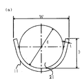
請求項1に記載の振動モータ取付け部材は、円筒形振動モータの胴部に溶接固定される振動モータ取付け部材であって、薄板から成りU字型に形成され、かつU字開口部の深さDが前記円筒形振動モータの胴部の半径d/2よりも大きく、かつ前記U字開口部Wが前記円筒形振動モータの胴部の直径dと振動モータ取付け部材の板厚tの2倍の合計より大きく、それらを固定搭載する剛体のケースの枠幅Wcよりも若干大きく設定されていることを特徴とする。[0006]
The vibration motor mounting member according to claim 1 is a vibration motor mounting member to be welded and fixed to a body portion of a cylindrical vibration motor, and is formed of a thin plate and formed in a U-shape, and a depth of a U-shaped opening D is larger than the radius d / 2 of the body of the cylindrical vibration motor, and the U-shaped opening W is twice the diameter d of the body of the cylindrical vibration motor and the thickness t of the vibration motor mounting member Is set to be slightly larger than the frame width Wc of the rigid case in which they are fixedly mounted.
【0008】
請求項2に記載の振動モータ取付け部材は、請求項1記載の振動モータ取付け部材において、前記振動モータ取付け部材の前記ケースに当たる側の面に突起が設けられ、前記突起が前記ケース側の対応する箇所の切り欠きに合致することを特徴とする。[0008]
The vibration motor mounting member according to claim 2 is the vibration motor mounting member according to claim 1, wherein a projection is provided on a surface of the vibration motor mounting member on the side that contacts the case, and the projection corresponds to the case side It features that it matches with the notch of the part.
【0010】
請求項3に記載の振動モータ取付け部材は、請求項1または2記載の振動モータ取付け部材において、前記溶接固定される箇所近傍に少なくとも1つの切り欠き部を設け、前記切り欠き部において除去された部分の表裏の面積の合計がその切断面の面積の合計より大きいことを特徴とする。[0010]
The vibration motor mounting member according to claim 3 is the vibration motor mounting member according to claim 1 or 2, wherein at least one notch is provided in the vicinity of the portion to be fixed by welding, and removed at the notch It is characterized in that the sum of the front and back areas of the part is larger than the sum of the areas of the cut surfaces.
【0013】
図1(a)および(b)は本発明の実施例を示す振動モータ取付け部材の展開図および成形後の形状を示す図である。振動モータ取付け部材11は金属の薄板でできており、展開図のように打ち抜き加工を施した後、U字型になるよう曲げ加工を施したものである。これをまず、円筒形振動モータ21に溶接固定する。このとき図2(a)および(b)に示すように振動モータ取付け部材11と円筒形振動モータ21の寸法関係は以下のとおりである。(1)振動モータ取付け部材11のU字部の深さDが円筒形振動モータ21の胴部の半径d/2よりも大きい。かつ(2)振動モータ取付け部材11のU字開口部Wが円筒形振動モータ21の胴部の直径dと振動モータ取付け部材11の板厚tの2倍の合計よりも大きい。かつ(3)振動モータ取付け部材11のU字開口部Wがそれらを固定搭載する剛体のケース22の枠幅Wcよりも若干大きい。このようにして振動モータ21を剛体のケース22に固定搭載すると、振動モータ取付け部材11のU字開口部がケース22の枠にあたり弾性変形が起こる。そのときの力の関係は図2(b)のようになり、振動モータ取付け部材11のばね力24の水平方向成分25とケース22からの反力28がつりあい、またばね力24の垂直方向成分26が振動モータ取付け部材11とケース22の間の摩擦力27とつりあうことによって、振動モータ21をケース22内に確実に組み付けることができる。このとき、振動モータ取り付け部材21は金属の薄板から成るため厚さ0。1mmとすることが充分可能であり、図3で示すゴム製の取付け部材31よりも固定搭載に必要な体積が少なくてすむし、図4で示すM字型の取付け部材41に較べてへり部分が無いために同じく固定搭載に必要な体積が少なくてすむ。[0013]
FIGS. 1A and 1B are a developed view of a vibration motor mounting member showing an embodiment of the present invention and a view showing a shape after molding. The vibration
Claims (3)
前記振動モータ取付け部材の前記ケースに当たる側の面に突起が設けられ、前記突起が前記ケース側の対応する箇所の切り欠きに合致することを特徴とする振動モータ取付け部材。In the vibration motor mounting member according to claim 1,
2. A vibration motor mounting member according to claim 1, wherein a protrusion is provided on a surface of the vibration motor mounting member on the side that contacts the case, and the protrusion matches a notch of a corresponding portion on the case side.
前記溶接固定される箇所近傍に少なくとも1つの切り欠き部を設け、前記切り欠き部において除去された部分の表裏の面積の合計がその切断面の面積の合計より大きいことを特徴とする振動モータ取付け部材。In the vibration motor mounting member according to claim 1 or 2,
At least one notch is provided in the vicinity of the portion to be welded and fixed, and the total of the area of the front and back of the portion removed in the notch is larger than the total of the area of the cut surface Element.
Priority Applications (1)
| Application Number | Priority Date | Filing Date | Title |
|---|---|---|---|
| JP2000095707A JP3758456B2 (en) | 2000-03-30 | 2000-03-30 | Vibration motor mounting member |
Applications Claiming Priority (1)
| Application Number | Priority Date | Filing Date | Title |
|---|---|---|---|
| JP2000095707A JP3758456B2 (en) | 2000-03-30 | 2000-03-30 | Vibration motor mounting member |
Publications (3)
| Publication Number | Publication Date |
|---|---|
| JP2001286092A JP2001286092A (en) | 2001-10-12 |
| JP2001286092A5 true JP2001286092A5 (en) | 2004-10-28 |
| JP3758456B2 JP3758456B2 (en) | 2006-03-22 |
Family
ID=18610570
Family Applications (1)
| Application Number | Title | Priority Date | Filing Date |
|---|---|---|---|
| JP2000095707A Expired - Fee Related JP3758456B2 (en) | 2000-03-30 | 2000-03-30 | Vibration motor mounting member |
Country Status (1)
| Country | Link |
|---|---|
| JP (1) | JP3758456B2 (en) |
Families Citing this family (1)
| Publication number | Priority date | Publication date | Assignee | Title |
|---|---|---|---|---|
| JP5047663B2 (en) * | 2007-03-29 | 2012-10-10 | 日本電産コパル株式会社 | Motor assembly |
-
2000
- 2000-03-30 JP JP2000095707A patent/JP3758456B2/en not_active Expired - Fee Related
Similar Documents
| Publication | Publication Date | Title |
|---|---|---|
| US8104179B2 (en) | Razor | |
| US8046920B2 (en) | Razor | |
| TW200300396A (en) | Speaker for vehicle and installation structure therefor | |
| JP3908500B2 (en) | Room lamp fixing structure | |
| JP2008216043A (en) | Rotation sensor | |
| JP2001286092A5 (en) | ||
| JP3758456B2 (en) | Vibration motor mounting member | |
| JP2005048838A (en) | Separate member stopper of engine mount | |
| JP2008232390A (en) | Engine mount | |
| JP6766695B2 (en) | Vehicle seat | |
| JP4660019B2 (en) | Groove lid with bounce prevention device | |
| CN113978400B (en) | Front structure of vehicle | |
| JP2020180690A (en) | Stopper for vibration isolation device | |
| JP6004889B2 (en) | Striker bracket | |
| JP3480277B2 (en) | Speaker net mounting device | |
| JP2007336736A (en) | Electromagnetic vibrator | |
| JP3246288B2 (en) | License plate mounting structure | |
| JP3209449U (en) | Wall mounting bracket | |
| JP4089552B2 (en) | Airbag device | |
| JP2006306314A (en) | Punched air bag retaining member and method for assembling air bag | |
| JP2004237933A (en) | Air bag module | |
| JP2020068073A (en) | Vehicular lamp structure and method for manufacturing the same | |
| JP2021189572A (en) | Display device for vehicle | |
| JP2001151256A (en) | Container with cover | |
| KR100828837B1 (en) | Glass holder for an automobile |