JP4089552B2 - Airbag device - Google Patents
Airbag device Download PDFInfo
- Publication number
- JP4089552B2 JP4089552B2 JP2003301008A JP2003301008A JP4089552B2 JP 4089552 B2 JP4089552 B2 JP 4089552B2 JP 2003301008 A JP2003301008 A JP 2003301008A JP 2003301008 A JP2003301008 A JP 2003301008A JP 4089552 B2 JP4089552 B2 JP 4089552B2
- Authority
- JP
- Japan
- Prior art keywords
- airbag
- bracket member
- case
- frame portion
- convex
- Prior art date
- Legal status (The legal status is an assumption and is not a legal conclusion. Google has not performed a legal analysis and makes no representation as to the accuracy of the status listed.)
- Expired - Lifetime
Links
Images


Landscapes
- Air Bags (AREA)
Description
この発明は、自動車などの車両に装備されるエアバッグ装置に関する。 The present invention relates to an airbag device equipped in a vehicle such as an automobile.
自動車等の車両の助手席に装備されるエアバッグ装置は、インフレータとエアバッグを収容するケース(リアクションカン)と、エアバッグの展開時に開くリッド部を有するエアバッグシュート部材とを含んでいる。このエアバッグシュート部材は助手席側のインストルメントパネルに設けられている。前記ケースは、デッキクロス等の車体部材に固定される。 An airbag device mounted on a passenger seat of a vehicle such as an automobile includes an inflator and a case (reaction can) that accommodates the airbag, and an airbag chute member that has a lid portion that opens when the airbag is deployed. The airbag chute member is provided on the instrument panel on the passenger seat side. The case is fixed to a vehicle body member such as a deck cloth.
この種のエアバッグ装置において、前記ケースとエアバッグシュート部材とを互いに組付けるために、下記特許文献1に記載されているように、ブラケット部材(押さえ部材)が使用されることがある。
In this type of airbag device, in order to assemble the case and the airbag chute member to each other, a bracket member (pressing member) may be used as described in
ブラケット部材を用いる従来のエアバッグ装置は、例えば図7に示すように、ケース1の周壁2に形成された凸部3を有している。エアバッグシュート部材4の枠部5には、凸部3が挿入される嵌合孔6が形成され、凸部3に取付孔7が形成されている。この取付孔7にブラケット部材8の挿入部9を挿入し、ブラケット部材8をケース1に固定する。
A conventional airbag device using a bracket member has a convex portion 3 formed on the peripheral wall 2 of the
このブラケット部材8によって、ケース1の凸部3がエアバッグシュート部材4の嵌合孔6から抜け出ることが阻止されるため、エアバッグB(図7に一部のみ図示する)の展開時に、エアバッグシュート部材4をケース1に確実に保持することができる。
前記従来のエアバッグ装置は、ケース1の周壁2とエアバッグシュート部材4の枠部5との間に若干の隙間Aがある。このため、ブラケット部材8の挿入部9を凸部3の取付孔7に挿入する際に、作業員が誤って前記隙間Aにブラケット部材8の挿入部9を差し込んでしまい、誤挿入に気付かないまま、ブラケット部材8がケース1に組付けられてしまうことが懸念される。
In the conventional airbag device, there is a slight gap A between the peripheral wall 2 of the
従ってこの発明の目的は、ブラケット部材が誤って組付けられてしまうことを防止できるエアバッグ装置を提供することにある。 Accordingly, an object of the present invention is to provide an airbag device that can prevent the bracket member from being assembled by mistake.
本発明のエアバッグ装置は、エアバッグを収容する周壁を有し該周壁の外面に凸部が形成されているケースと、前記エアバッグの展開時に開くリッド部と該リッド部の裏面側に形成された枠部を有し該枠部に前記凸部が挿入される嵌合孔が形成されたエアバッグシュート部材と、前記凸部に形成された取付孔に挿入される挿入部を有し該挿入部を前記取付孔に挿入した状態で前記枠部の外面に重ねて前記ケースに固定されるブラケット部材とを備えている。さらにこのブラケット部材には、前記挿入部が前記ケースの周壁と前記エアバッグシュート部材の枠部との間の隙間に誤挿入されたとき前記枠部の縁に当接する誤組防止用凸部が形成されている。 The airbag device of the present invention includes a case having a peripheral wall that accommodates the airbag, a convex portion formed on the outer surface of the peripheral wall, a lid portion that is opened when the airbag is deployed, and a back surface side of the lid portion. An air bag chute member in which a fitting hole into which the convex portion is inserted is formed in the frame portion, and an insertion portion to be inserted into an attachment hole formed in the convex portion. A bracket member that is fixed to the case so as to overlap the outer surface of the frame portion in a state where the insertion portion is inserted into the mounting hole. Further, the bracket member has a misassembly prevention convex portion that abuts against an edge of the frame portion when the insertion portion is erroneously inserted into a gap between the peripheral wall of the case and the frame portion of the airbag chute member. Is formed.
この発明では、前記誤組防止用凸部は、板金からなる前記ブラケット部材の一部を折曲げてなる立ち上がり部と、該立ち上がり部の先端側から前記挿入部と同じ方向を向くように折曲された屈曲部とを有している。 In this inventions, the erroneous assembly preventing projections, so as to face the rising portion formed by bending a portion of said bracket member made of sheet metal, the same direction as the insertion portion from the front end side of the rising portion And a bent portion that is bent.
この発明によれば、ブラケット部材に誤組防止用凸部を設け、該ブラケット部材の挿入部がケースの周壁とエアバッグシュート部材の枠部との間の隙間に誤挿入されたときに誤組防止用凸部が前記枠部の縁に当接するようにしたことにより、誤挿入時にこのブラケット部材を所定位置まで挿入することができなくなる。このため、ブラケット部材が誤って組付けられてしまうことを防止できる。 According to the present invention, the bracket member is provided with a projection for preventing misassembly, and the bracket member is misassembled when the insertion portion of the bracket member is erroneously inserted into the gap between the peripheral wall of the case and the frame portion of the airbag chute member. Since the preventing convex portion is brought into contact with the edge of the frame portion, the bracket member cannot be inserted to a predetermined position at the time of erroneous insertion. For this reason, it can prevent that a bracket member will be assembled | attached accidentally.
この発明では、誤組防止用凸部に立ち上がり部と屈曲部を設けているため、ブラケット部材の誤挿入をさらに確実に防止することができる。 In the present invention, since the a and the bent portion rising portion for erroneous assembly preventing protrusions may be provided to more reliably prevent the erroneous insertion of the bracket member.
以下に本発明の一実施形態について、図1から図6を参照して説明する。
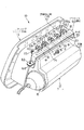
図1に示す助手席用エアバッグ装置10は、自動車の助手席側のインストルメントパネル11(図5に一部のみ図示する)に設けられ、助手席に着座した乗員を保護するものである。このエアバッグ装置10は、金属製のケース12と、インストルメントパネル11に取付けるエアバッグシュート部材13とを備えている。
Hereinafter, an embodiment of the present invention will be described with reference to FIGS.
A passenger
ケース12は、インフレータ15とエアバッグ16(図5に一部を示す)を収容する周壁17を有している。このケース12は、デッキクロス等の車体部材に固定される。周壁17の上面に、外方に向かって突出する複数の凸部18が形成されている。これら凸部18は、ケース12の幅方向(車体の幅方向)に所定間隔で形成されている。凸部18に、取付孔19が形成されている。この取付孔19に、後述するブラケット部材60の挿入部63が挿入される。
The
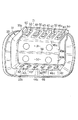
図2に示されるようにエアバッグシュート部材13は、エアバッグ16の展開時に開く一対のリッド部31,32と、リッド部31,32の裏面側に形成された枠部33とを有している。リッド部31,32間の境界部34は、エアバッグ16の展開時に破断しやすいように、厚さが他の部位よりも薄くなっているが、エアバッグ16が展開する前は互いにつながっている。
As shown in FIG. 2, the
エアバッグシュート部材13の枠部33の上壁33aに、複数の嵌合孔40が形成されている。これらの嵌合孔40は、凸部18と対応した位置に、凸部18と等ピッチで形成されている。これらの嵌合孔40に凸部18が挿入される。
A plurality of fitting
図4に示されるように、ケース12の下面にフック部材41が設けられている。このフック部材41は、エアバッグシュート部材13の枠部33の下壁33bに形成された係止孔42に挿入される。フック部材41の先端41aは、インフレータ15側を向くように折曲げられている。
As shown in FIG. 4, a hook member 41 is provided on the lower surface of the
図2に示されるように、上側に位置する一方のリッド部31と枠部33の上壁33aとにわたって、薄い金属板からなるヒンジ部材45が設けられている。下側に位置する他方のリッド部32と枠部33の下壁33bとにわたって、薄い金属板からなるヒンジ部材46が設けられている。これらのヒンジ部材45,46は、エアバッグシュート部材13を樹脂によって成形する際に、エアバッグシュート部材13の樹脂部13a(図4と図5に示す)と一体にインサート成形されている。
As shown in FIG. 2, a
図2と図5に示すように、一方のヒンジ部材45は、リッド部31が開く際にヒンジとして機能する曲がり部45aと、リッド部31に埋設された第1プレート部45bと、枠部33の上壁33aの内面に貼り付いている第2プレート部45cとを有している。第2プレート部45cは、インサート成形される樹脂部13aの接着力によって、枠部33の上壁33aに固定されている。第2プレート部45cには、上壁33aの嵌合孔40と対応した位置にほぼ矩形の開口部50(図2に示す)が形成されている。
As shown in FIGS. 2 and 5, one
他方のヒンジ部材46も、リッド部32が開く際にヒンジとして機能する曲がり部46aと、リッド部32に埋設された第1プレート部46bと、枠部33の下壁33bの内面に貼り付いている第2プレート部46cとを有している。第2プレート部46cは、インサート成形される樹脂部13aの接着力によって、枠部33の下壁33bに固定されている。第2プレート部46cには、下壁33bの係止孔42と対応した位置に開口部51(図4に示す)が形成されている。
The
図5に示されるように、リッド部31,32の表面に、ウレタン等の弾性を有する樹脂からなるカバー材55が設けられている。インストルメントパネル11の表面にも、弾性を有する樹脂からなるカバー材55が設けられている。
As shown in FIG. 5, a
ケース12の上部とエアバッグシュート部材13の上部は、以下に説明する板金製のブラケット部材60によって互いに組付けられる。ケース12の下部とエアバッグシュート部材13の下部は、図4に示されるように、フック部材41を係止孔42に挿入することにより、互いに組付けられる。
The upper part of the
図3に示すようにブラケット部材60は、細長い形状の基部61と、基部61の両端に形成された取付部62と、複数の挿入部63とを有している。基部61は、エアバッグシュート部材13の枠部33に沿っている。挿入部63は、基部61の長手方向に沿って、前記凸部18と等ピッチで形成されている。
As shown in FIG. 3, the
これら挿入部63は、凸部18に形成された取付孔19に挿入可能な形状であり、基部61の前方に突き出ている。このブラケット部材60は、各挿入部63を取付孔19に挿入した状態で、枠部33の外面に重ね、ボルト等の固定部材65(図1に一方のみ示す)によって、ケース12の支持部66に固定される。
These
ブラケット部材60に誤組防止用凸部70が形成されている。この誤組防止用凸部70は、ブラケット部材60の組付作業を行なう際に、挿入部63がケース12の周壁17とエアバッグシュート部材13の枠部33との間の隙間Gに挿入されたとき、図6に示すように枠部33の縁71に当接するようになっている。
The
この誤組防止用凸部70は、例えばプレス成形によって、ブラケット部材60の一部をおおむね直角に折曲された立ち上がり部72と、この立ち上がり部72の先端側から挿入部63と同じ方向を向くように、おおむね直角に折曲された屈曲部73とを有している。
The projection for preventing
このため、ブラケット部材60を組付ける際に、誤って挿入部63を前記隙間Gに差し込むと、図6に示すように、誤組防止用凸部70が枠部33の縁71に当接する。このため、それ以上奥までブラケット部材60を挿入することができなくなる。このことによって作業者は、ブラケット部材60の位置が誤っていることを認識することができ、ブラケット部材60が誤った位置に組付けられてしまうことを防止できる。
For this reason, when the
しかもこの実施形態の誤組防止用凸部70は、立ち上がり部72の先端側に屈曲部73を有しているため、挿入部63が隙間Gに差し込まれたとき、力ずくで無理やり隙間Gに押し込もうとしても、屈曲部73が枠部33の縁71に引っ掛ってしまい、それ以上挿入できなくなる。このため、ブラケット部材60の誤挿入をさらに確実に防止することができる。この誤組防止用凸部70は、プレス成形によって容易に形成することができる。
In addition, since the
10…エアバッグ装置
12…ケース
13…エアバッグシュート部材
16…エアバッグ
17…周壁
18…凸部
19…取付孔
31,32…リッド部
33…枠部
40…嵌合孔
60…ブラケット部材
63…挿入部
70…誤組防止用凸部
DESCRIPTION OF
Claims (1)
前記エアバッグの展開時に開くリッド部と該リッド部の裏面側に形成された枠部を有し該枠部に前記凸部が挿入される嵌合孔が形成されたエアバッグシュート部材と、
前記凸部に形成された取付孔に挿入される挿入部を有し、該挿入部を前記取付孔に挿入した状態で前記枠部の外面に重ねて前記ケースに固定されるブラケット部材とを具備し、
該ブラケット部材には、前記挿入部が前記ケースの周壁と前記エアバッグシュート部材の枠部との間の隙間に誤挿入されたとき前記枠部の縁に当接する誤組防止用凸部が形成され、この誤組防止用凸部は、板金からなる前記ブラケット部材の一部を折曲げてなる立ち上がり部と、該立ち上がり部の先端側から前記挿入部と同じ方向を向くように折曲された屈曲部とを有していることを特徴とするエアバッグ装置。 A case having a peripheral wall for accommodating an airbag, and a convex portion formed on the outer surface of the peripheral wall;
An airbag chute member having a lid portion that is opened when the airbag is deployed and a frame portion formed on the back side of the lid portion, and a fitting hole into which the convex portion is inserted is formed in the frame portion;
A bracket member that has an insertion portion that is inserted into an attachment hole formed in the convex portion, and is fixed to the case so as to overlap the outer surface of the frame portion in a state in which the insertion portion is inserted into the attachment hole. And
The bracket member is formed with a projection for preventing misassembly when the insertion portion is erroneously inserted into a gap between the peripheral wall of the case and the frame portion of the airbag chute member. The convex portion for preventing misassembly is bent so that a part of the bracket member made of sheet metal is bent, and the leading end side of the rising part faces the same direction as the insertion part. An airbag device comprising a bent portion .
Priority Applications (1)
| Application Number | Priority Date | Filing Date | Title |
|---|---|---|---|
| JP2003301008A JP4089552B2 (en) | 2003-08-26 | 2003-08-26 | Airbag device |
Applications Claiming Priority (1)
| Application Number | Priority Date | Filing Date | Title |
|---|---|---|---|
| JP2003301008A JP4089552B2 (en) | 2003-08-26 | 2003-08-26 | Airbag device |
Publications (2)
| Publication Number | Publication Date |
|---|---|
| JP2005067439A JP2005067439A (en) | 2005-03-17 |
| JP4089552B2 true JP4089552B2 (en) | 2008-05-28 |
Family
ID=34405755
Family Applications (1)
| Application Number | Title | Priority Date | Filing Date |
|---|---|---|---|
| JP2003301008A Expired - Lifetime JP4089552B2 (en) | 2003-08-26 | 2003-08-26 | Airbag device |
Country Status (1)
| Country | Link |
|---|---|
| JP (1) | JP4089552B2 (en) |
Families Citing this family (1)
| Publication number | Priority date | Publication date | Assignee | Title |
|---|---|---|---|---|
| JP5425536B2 (en) * | 2009-06-19 | 2014-02-26 | 本田技研工業株式会社 | Mounting structure for vehicle airbag device |
-
2003
- 2003-08-26 JP JP2003301008A patent/JP4089552B2/en not_active Expired - Lifetime
Also Published As
| Publication number | Publication date |
|---|---|
| JP2005067439A (en) | 2005-03-17 |
Similar Documents
| Publication | Publication Date | Title |
|---|---|---|
| US7055849B2 (en) | Cover for air bag device | |
| JP4636490B2 (en) | Airbag unit | |
| JP2642083B2 (en) | Switch board holding structure for small electronic equipment | |
| JP5033186B2 (en) | Device for snap-fixing an air bag unit to a subassembly in an automobile vehicle, in particular a steering wheel | |
| US7862273B2 (en) | Part mounting mechanism | |
| JP6508603B2 (en) | Sensor bracket | |
| US7222906B2 (en) | Mounting structure for console | |
| JP4132983B2 (en) | Clip mounting structure | |
| JP2006074845A (en) | Protector | |
| KR20170132366A (en) | Air bag device for driver | |
| JP2018167723A (en) | Mounting structure for functional parts for vehicles | |
| JP4089552B2 (en) | Airbag device | |
| JPWO2007013635A1 (en) | Airbag device | |
| JP6535925B2 (en) | Airbag module | |
| JP2002195225A (en) | Mounting structure for electric apparatus | |
| JP3890905B2 (en) | Airbag device | |
| JPH0899594A (en) | Cover for airbag module | |
| JP7508385B2 (en) | Anchor structure and harness protection equipment | |
| JP6052602B2 (en) | Front pillar trim and instrument panel alignment structure | |
| JP2005328024A (en) | Control unit case | |
| JP3891385B2 (en) | Cup holder structure | |
| JP2006262667A (en) | Lock structure of wire harness protector | |
| JP2005339880A (en) | Connector terminal structure of switch case | |
| JP4504764B2 (en) | Instrument panel connector mounting structure and instrument panel assembly method | |
| JP2003025943A (en) | Air bag system |
Legal Events
| Date | Code | Title | Description |
|---|---|---|---|
| A621 | Written request for application examination |
Free format text: JAPANESE INTERMEDIATE CODE: A621 Effective date: 20051021 |
|
| A131 | Notification of reasons for refusal |
Free format text: JAPANESE INTERMEDIATE CODE: A131 Effective date: 20071030 |
|
| A977 | Report on retrieval |
Free format text: JAPANESE INTERMEDIATE CODE: A971007 Effective date: 20071101 |
|
| A521 | Request for written amendment filed |
Free format text: JAPANESE INTERMEDIATE CODE: A523 Effective date: 20071210 |
|
| TRDD | Decision of grant or rejection written | ||
| A01 | Written decision to grant a patent or to grant a registration (utility model) |
Free format text: JAPANESE INTERMEDIATE CODE: A01 Effective date: 20080205 |
|
| A61 | First payment of annual fees (during grant procedure) |
Free format text: JAPANESE INTERMEDIATE CODE: A61 Effective date: 20080218 |
|
| R151 | Written notification of patent or utility model registration |
Ref document number: 4089552 Country of ref document: JP Free format text: JAPANESE INTERMEDIATE CODE: R151 |
|
| FPAY | Renewal fee payment (event date is renewal date of database) |
Free format text: PAYMENT UNTIL: 20110307 Year of fee payment: 3 |
|
| FPAY | Renewal fee payment (event date is renewal date of database) |
Free format text: PAYMENT UNTIL: 20110307 Year of fee payment: 3 |
|
| FPAY | Renewal fee payment (event date is renewal date of database) |
Free format text: PAYMENT UNTIL: 20120307 Year of fee payment: 4 |
|
| FPAY | Renewal fee payment (event date is renewal date of database) |
Free format text: PAYMENT UNTIL: 20120307 Year of fee payment: 4 |
|
| FPAY | Renewal fee payment (event date is renewal date of database) |
Free format text: PAYMENT UNTIL: 20130307 Year of fee payment: 5 |
|
| FPAY | Renewal fee payment (event date is renewal date of database) |
Free format text: PAYMENT UNTIL: 20140307 Year of fee payment: 6 |
|
| S531 | Written request for registration of change of domicile |
Free format text: JAPANESE INTERMEDIATE CODE: R313531 |
|
| R350 | Written notification of registration of transfer |
Free format text: JAPANESE INTERMEDIATE CODE: R350 |
|
| EXPY | Cancellation because of completion of term |