EP4583582A2 - Anpassung eines mobilen netzwerks - Google Patents
Anpassung eines mobilen netzwerks Download PDFInfo
- Publication number
- EP4583582A2 EP4583582A2 EP25166634.3A EP25166634A EP4583582A2 EP 4583582 A2 EP4583582 A2 EP 4583582A2 EP 25166634 A EP25166634 A EP 25166634A EP 4583582 A2 EP4583582 A2 EP 4583582A2
- Authority
- EP
- European Patent Office
- Prior art keywords
- access node
- connection
- user equipment
- mobile network
- terminal
- Prior art date
- Legal status (The legal status is an assumption and is not a legal conclusion. Google has not performed a legal analysis and makes no representation as to the accuracy of the status listed.)
- Pending
Links
Images


Classifications
-
- H—ELECTRICITY
- H04—ELECTRIC COMMUNICATION TECHNIQUE
- H04W—WIRELESS COMMUNICATION NETWORKS
- H04W36/00—Hand-off or reselection arrangements
- H04W36/24—Reselection being triggered by specific parameters
- H04W36/30—Reselection being triggered by specific parameters by measured or perceived connection quality data
- H04W36/305—Handover due to radio link failure
-
- H—ELECTRICITY
- H04—ELECTRIC COMMUNICATION TECHNIQUE
- H04W—WIRELESS COMMUNICATION NETWORKS
- H04W36/00—Hand-off or reselection arrangements
- H04W36/0005—Control or signalling for completing the hand-off
- H04W36/0055—Transmission or use of information for re-establishing the radio link
- H04W36/0069—Transmission or use of information for re-establishing the radio link in case of dual connectivity, e.g. decoupled uplink/downlink
- H04W36/00695—Transmission or use of information for re-establishing the radio link in case of dual connectivity, e.g. decoupled uplink/downlink using split of the control plane or user plane
-
- H—ELECTRICITY
- H04—ELECTRIC COMMUNICATION TECHNIQUE
- H04W—WIRELESS COMMUNICATION NETWORKS
- H04W36/00—Hand-off or reselection arrangements
- H04W36/24—Reselection being triggered by specific parameters
- H04W36/30—Reselection being triggered by specific parameters by measured or perceived connection quality data
-
- H—ELECTRICITY
- H04—ELECTRIC COMMUNICATION TECHNIQUE
- H04W—WIRELESS COMMUNICATION NETWORKS
- H04W36/00—Hand-off or reselection arrangements
- H04W36/0005—Control or signalling for completing the hand-off
- H04W36/0055—Transmission or use of information for re-establishing the radio link
-
- H—ELECTRICITY
- H04—ELECTRIC COMMUNICATION TECHNIQUE
- H04W—WIRELESS COMMUNICATION NETWORKS
- H04W36/00—Hand-off or reselection arrangements
- H04W36/0005—Control or signalling for completing the hand-off
- H04W36/0055—Transmission or use of information for re-establishing the radio link
- H04W36/0064—Transmission or use of information for re-establishing the radio link of control information between different access points
-
- H—ELECTRICITY
- H04—ELECTRIC COMMUNICATION TECHNIQUE
- H04W—WIRELESS COMMUNICATION NETWORKS
- H04W36/00—Hand-off or reselection arrangements
- H04W36/04—Reselecting a cell layer in multi-layered cells
-
- H—ELECTRICITY
- H04—ELECTRIC COMMUNICATION TECHNIQUE
- H04W—WIRELESS COMMUNICATION NETWORKS
- H04W36/00—Hand-off or reselection arrangements
- H04W36/24—Reselection being triggered by specific parameters
- H04W36/30—Reselection being triggered by specific parameters by measured or perceived connection quality data
- H04W36/302—Reselection being triggered by specific parameters by measured or perceived connection quality data due to low signal strength
Definitions
- the present disclosure relates to telecommunications and in particular to methods for adapting a mobile network. Nodes, a communication system, computer programs, and computer program products are also described.
- LTE Long Term Evolution
- UMTS Evolved Universal Terrestrial Radio Access Network
- E-UTRAN Evolved Universal Terrestrial Radio Access Network
- LTE is used as an example technology where the embodiments are suitable, and using LTE in the description therefore is particularly useful for understanding the problem and solutions solving the problem.
- a UE in LTE can be in two RRC states: RRC_CONNECTED and RRC_IDLE.
- RRC_CONNECTED state mobility is network-controlled based on e.g. measurements provided by the UE. I.e. the network decides when and to which cell an UE should be handed over, based on e.g. measurements provided by the UE.
- the network i.e. the LTE radio base station (called evolved Node Base station (eNodeB or eNB), respectively, in E-UTRAN) configures various measurement events, thresholds etc. based on which the UE then sends reports to the network, such that the network can make a wise decision to hand over the UE to a stronger cell as the UE moves away from the present cell.
- eNodeB or eNB evolved Node Base station
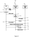
- FIG. 1 illustrates a LTE RRC handover procedure according to 3GPP TS 36.300, e.g. V11.4.0 (2013-01), Fig. 10 .1.2.1.1-1.
- Fig. 1 illustrates a LTE RRC handover procedure.
- a UE 102 is connected to a source eNodeB 104 of a LTE radio access network, which is controlled by a Mobility Management Entity (MME) 106 of a packet switched domain of a core network.
- MME Mobility Management Entity
- a target eNodeB 108 is controlled by the MME 106.
- the user equipment 102 is exchanging data with a serving gateway 110 of the core network.
- MME Mobility Management Entity
- the user equipment 102 is handed over from the source eNodeB 102 to the target eNodeB 108 of the radio access network.
- Corresponding user data signaling is indicated by dashed arrows.
- L3 control signaling is indicated by dotted dashed arrows, and L1/L2 control signaling is indicated by solid arrows.
- the source eNodeB 104 sends in a first step 1 management control information to the user equipment 102, which in turn sends corresponding measurement reports in a step 2 to the source eNodeB 104.
- a step 210 in which a measurement configuration is sent from the source eNodeB 204 to the user equipment 202, the user equipment 202 performs in a step 212 an A3 event in which a signal strength or signal quality of the target eNodeB 208 may be detected to be better compared to a signal strength or signal quality of the source eNodeB 204, respectively, and accordingly reports in a step 214 a measurement report to the source eNodeB 204.
- the source eNodeB 204 sends a handover request in a step 218 to the target eNodeB 208, which in turn sends a handover acknowledgement in a step 220 to the source eNodeB 204.
- the source eNodeB 204 then sends in a step 222 a handover command to the user equipment 202, which performs in a step 224 a random access procedure in which dedicated preambles are submitted to the target eNodeB 208.
- Further arrows 226-230 relate to a completion of the handover procedure.
- an uplink (UL) grant and a Tracking Area (TA) may be sent from the target eNodeB 208 to the UE 202.
- a HO confirm may be sent from the UE 202 to the target eNodeB 208.
- a Release context may be sent from the target eNodeB 208 to the source eNodeB 204.
- the steps 210, 214, 216, 218, 220, 222, 224 correspond to the steps 1, 2, 3, 4, 6, 7, and 11 in Fig. 1 .
- UE-based cell-selection where a nomadic UE 102, 202 selects the "best" cell to camp on, based e.g. on various specified criteria and parameters that are broadcasted in the cells. For example, various cells or frequency layers could be prioritized over other, such that the UE 102, 202 tries to camp on a particular cell as long as the measured quality of a beacon or pilot in that cell is a threshold better than some other beacon or pilot received from other cells.
- the present disclosure is primarily focusing on problems associated with network-controlled mobility as described above, i.e. for an LTE UE in RRC_CONNECTED state.
- the problems associated with failing handovers are therefore described in further detail below.
- the exemplified measurement report is triggered by a so called A3 event in the step 212 which, in short, corresponds to the scenario in which a neighbor cell is found to be an offset better than the current serving cell. It should be noted that there are multiple events that can trigger a report.
- a UE102, 202 looses coverage to the cell that the UE 102, 202 is currently connected to. This could occur in a situation when a UE 102, 202 enters a fading dip, or that a handover was needed as described above, but the handover failed for one or another reason. This is particularly true if the "handover region" is very short.
- the radio link quality e.g. on the physical layer as described in 3GPP TS 36.300, e.g. V11.4.0 (2013-01), TS 36.331, e.g. V11.2.0 (2013-01), and TS 36.133, e.g.
- the UE 102, 202 itself is able to declare a radio link failure and autonomously start a RRC re-establishment procedure. If the re-establishment is successful, which depends, among other things, if the selected cell and the eNB 104, 108, 204, 208 controlling that cell was prepared to maintain the connection to the UE 102, 202, then the connection between the UE 102, 202 and the eNB 104, 108, 204, 208 can resume.
- a failure of a re-establishment means that the UE 102, 202 goes to RRC_ IDLE and the connection is released. To continue a communication, a brand new RRC connection has then to be requested and established.
- Dual connectivity is a feature defined from the UE perspective wherein the UE may simultaneously receive and transmit to at least two different network points.
- the at least two network points may be connected to one another via a backhaul link such that a UE may be enabled to communicate with one of the network points via the other network point.
- Dual connectivity is one of the features that are being standardized within the umbrella work of small cell enhancements within 3GPP Release 12 (Rel-12).
- Dual connectivity is defined for the case when the aggregated network points operate on the same or separate frequency.
- Each network point that the UE is aggregating may define a stand-alone cell or it may not define a stand-alone cell.
- the term "stand-alone cell" may particularly denote that each network point, hence each cell, may represent a separate cell from a perspective of a UE.
- network points not defining a stand-alone cell may be regarded from a perspective of a UE as one same cell. It is further foreseen that from the UE perspective the UE may apply some form of Time Division Multiplex (TDM) scheme between the different network points that the UE is aggregating. This implies that the communication on the physical layer to and from the different aggregated network points may not be truly simultaneous.
- TDM Time Division Multiplex
- Dual connectivity as a feature bears many similarities with carrier aggregation and coordinated multi-point (CoMP).
- the main differentiating factor is that dual connectivity is designed considering a relaxed backhaul and less stringent requirements on synchronization requirements between the network points. This is in contrast to carrier aggregation and CoMP, wherein tight synchronization and a low-delay backhaul are assumed between connected network points.
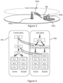
- Figure 3 illustrates the feature of dual connectivity of a UE 302 to an anchor 304a and a booster 304b.
- a UE 302 in dual connectivity maintains simultaneous connections 334a, 334b to anchor and booster nodes 304a, 304b.
- the anchor node 304a terminates the control plane connection towards the UE 302 and is thus the controlling node of the UE 302.
- the UE 302 also reads system information from the anchor 304a. In Fig. 3 , the system information and a spatial availability thereof are indicated by a dashed circle.
- the UE 302 may be connected to one or several booster nodes 304b for added user plane support.
- the term "booster" may denote that a performance of a UE in terms of its data peak rate may be improved, since user plane data may be additionally transmitted via the booster.
- a transmission frequency employed by the anchor may be different from a transmission frequency employed by the booster.
- the anchor and booster roles are defined from a UE 302 point of view. This means that a node that acts as an anchor 304a to one UE 302 may act as booster 304b to another UE 302. Similarly, though the UE 302 reads the system information from the anchor node 304a, a node acting as a booster 304b to one UE 302, may or may not distribute system information to another UE 302.
- Figure 4 illustrates a control and user plane termination in an anchor node and a booster node.
- This protocol architecture may represent an exemplary protocol termination compliant with dual connectivity and RRC diversity.
- the protocol architecture shown in Figure 4 is proposed as a way forward for realizing dual connectivity in LTE Rel-12 in deployments with relaxed backhaul requirements.
- PDCP Packet Data Convergence Protocol
- RLC Radio Link Control
- MPTCP Multipath Transmission Control Protocol
- NAS may represent a Non Access Stratum protocol layer
- RLC Radio Resource Control protocol layer
- MAC may represent Medium Access Control protocol layer
- PHYS Packet Data Convergence Protocol
- Heterogeneous Networks may result in an increased rate of handover failures, as briefly discussed above.
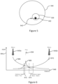
- the handover region in Heterogeneous Networks may be very short, meaning that the handover might fail since the UE lost coverage to the source cell before the handover to a target cell could be completed. For example, when a UE leaves a pico-cell, it may happen that the coverage border of the pico is so sharp, that the UE fails to receive any handover command towards a macro before loosing coverage to the pico, see Figure 5 or 6 .
- KPI key performance indication
- the term "key performance indication” may particularly denote information collected by a network, which information may relate to a performance characteristic of the network such that a corresponding managing network operator may accordingly adapt the network.
- a KPI may relate to handover failures and may indicate information such as how often a handover may occur, in which area the handover may occur, a reason for the occurrence of the handover etc.
- drive testing may particularly denote a procedure in which dedicated testing device, e.g. a user equipment, may move through the network, e.g. may drive around", and may test network characteristics related to e.g. connectivity.
- an entity e.g. a software may be installed spatially fixed in the network and may collect corresponding information from user equipments in the network.
- the collected information has time stamp information based on an UE internal clock and also location information.
- Drive testing and using specific UE's for drive testing may not always be able to discover intermittent faults or drive into locations where the problem actually occurs. If it is a UE vendor specific problem the UE used for drive testing may not have the same kind of fault as some of the UE's used by subscribers in the network. On top of that regular drive testing is typically very expensive. There is a large cost for collecting the data and also a cost when data is analyzed. The data analysis can be costly and difficult due to that drive testers need to collect all data on rather detailed level and hope that the intermittent fault appears and are captured in the data collected during drive testing amongst the large amount of data collected.
- KPI evaluation by the radio network for UEs experiencing radio link problems in certain locations at a certain time is problematic due to the degraded connectivity to the UE in these situations.
- the evaluation cannot be done immediately after the fault and is usually based on reports or (costly) drive tests. An immediate adaption of the system possibly improving the KPIs is thus not possible.
- a method for adapting a mobile network is provided.
- a terminal is connected to a first access node of the mobile network via a first connection and to a second access node via a second connection.
- the first access node controls a data transmission for the terminal and the second access node assists in the data transmission for the terminal.
- the method comprises determining whether a quality of at least one of the first connection and the second connection is degraded, acquiring quality degradation information about the degradation of the quality of at least one of the first connection and the second connection based on the step of determining, and adapting the mobile network based on the step of acquiring.
- a method for adapting a mobile network is provided.
- a terminal is connected to a first access node of the mobile network via a first connection and to a second access node via a second connection.
- the first access node controls a data transmission for the terminal and the second access node assists in the data transmission for the terminal.
- the method is performed by the second access node and comprises adapting the mobile network based on a quality of at least one of the first connection and the second connection being degraded.
- a terminal for adapting a mobile network is provided.
- the terminal is connected to a first access node of the mobile network via a first connection and to a second access node via a second connection.
- the first access node controls a data transmission for the terminal and the second access node assists in the data transmission for the terminal.
- the terminal comprises a determination unit adapted to determine whether a quality of at least one of the first connection and the second connection is degraded, and an acquiring unit adapted to acquire quality degradation information about the degradation of the quality of at least one of the first connection and the second connection based on the determination particularly for adapting the mobile network.
- an access node for adapting a mobile network is provided.
- a terminal is connected to the access node of the mobile network via a connection and to another access node via another second connection.
- the access node controls a data transmission for the terminal and the another access node assists in the data transmission for the terminal.
- the access node comprises an acquiring unit adapted to acquire quality degradation information about a degradation of a quality of at least one of the first connection and the second connection, and an adapting unit adapted to adapt the mobile network based on the acquired quality degradation information.
- an access node for adapting a mobile network is provided.
- a terminal is connected to the access node of the mobile network via a connection and to another access node via another connection.
- the another access node controls a data transmission for the terminal and the access node assists in the data transmission for the terminal.
- the access node comprises an adapting unit adapted to adapt the mobile network based on, particularly subsequent to, a quality of at least one of the connection and the another connection being degraded.
- a mobile network comprises a terminal according to the fifth exemplary aspect, a first access node according to the sixth exemplary aspect and a second access node according to seventh exemplary aspect.
- a computer program when being executed by a processor, is adapted to carry out or control a method for adapting a mobile network according to any one of the first, second, third or fourth exemplary aspect.
- a computer program product comprises program code to be executed by at least one processor, thereby causing the at least one processor to execute a method according to any one of the first, second, third or fourth exemplary aspect.
- data in a data transmission for a terminal, data may be transmitted from a first access node to the terminal via a first connection and data duplicates may be sent from a second access node to the terminal via a second connection.
- data transmission may relate to transmitting signaling data and/or payload data in an uplink direction from the terminal to the mobile network and/or in a downlink direction from the mobile network to the terminal.
- the first access node may have duplicated the respective data and may have sent the data duplicates to the second access node via a backhaul connection between the first access node and second access node.
- the first connection and the second connection may be independent from one another, and may comprise respective radio bearers to be established related to the data transmission.
- the first access node may control the data transmission for the terminal and the second access node may assist in the data transmission for the terminal.
- the term "the first access node controlling a data transmission of the terminal” may particularly denote to a control, by the first access node, of resource allocation for uplink and/or downlink data transmission for the terminal and/or a connectivity state of the terminal.
- the first access node can be also referred to as an anchor node for the data transmission of the terminal, for example, always being employed for the data transmission for the terminal.
- Such a communication scenario may be accomplished in LTE by terminating a protocol related to the allocation of resources via the air interface between the terminal and the first access node, particularly a RRC protocol, in the first access node.
- a PDCP protocol may be terminated in the first access node.
- the term "the second access node assisting in the data transmission for the terminal” may particularly denote that the second access node may be free of a capability of controlling the data transmission to the terminal, but may relay the uplink and/or downlink data transmission between the access node and the terminal.
- the second access node can be referred to as a booster node for the data transmission of the terminal, for example, being employed for the data transmission for the terminal as relay node.
- information sent between the first access node and the terminal may be duplicatedly sent between the first access node and the terminal via the second access node.
- At least one of the first and second connections may comprise a degraded quality.
- a quality of the first connection and/or the second connection may be determined, respective quality degradation information indicating that a quality of the first connection and/or the second connection may be degraded may be acquired based on the step of determining, and, based on the step of acquiring, the mobile network may be adapted.
- the term "acquiring information" may relate to an entity obtaining information by means of internally determining information and/or obtaining information by means of receiving information over the mobile network.
- connectivity degradation of a connectivity between the terminal and the first access node and/or the second access node may be handled in an efficient, easy and fast way. An overall system performance may be therefore improved.
- the first access node may be referred in described embodiments as “Source eNB” and the first connection may refer to an “anchor” connection 332a in Figure 3 .
- the second access node may be referenced in the described embodiments as “Assisting eNB”, and the second connection may refer to the "booster" connection 332b in Figure 3 .
- the target eNB 108, 208 described in connection with Figures 1 and 2 may also represent an access node adapted to control the data transmission for the terminal depending on being a transmission controlling access node or not.
- the step of adapting the mobile network may comprise adapting at least one connection between the terminal and the mobile network based on the step of determining.
- the terminal may be part of the mobile network.
- the step of determining may result in the first connection comprising a degraded quality
- the step of adapting may comprise handing, by the first access node, the terminal over from the first access node to the second access node and disconnecting the first connection.
- the first access node may initiate the handover of the terminal by sending a handover request to the second access node.
- the second access node may then forward or relay the handover request to the terminal.
- the first access node may stop controlling the data transmission of the terminal. In LTE the latter performed step may relate to stop RRC diversity.
- RRC diversity employed in the first access node may relate to a sending of data directly to the terminal and to a sending of duplicates of the data, which may be sent by the first access node to the terminal, to the second access node for relaying them by the second access node to the terminal.
- the data may comprise control signaling.
- stopping RRC diversity may refer to not duplicating the sent data anymore, thus maintaining only the direct connection to the terminal to keep legacy functionality. This legacy connection may be handed over to the second access node. Or in other words, particularly with respect to LTE, the latter may relate to stopping RRC signal duplication and forwarding to the second access node.
- the first access node may control the disconnection of the terminal, for example by sending a RRC reconfiguration request message to the terminal via the second access node.
- the step of adapting may further comprise transferring, by the first access node, control capabilities for controlling the data transmission of the terminal from the first access node to the second access node.
- a signaling bearer between the first access node and the terminal may be transferred to the second access node, which bearer may transport a control signaling.
- the latter mentioned embodiments may be described later with reference to steps 8, 9, 11 and a resulting step or state 999 of Figure 9 .
- the step of determining may result in the second connection comprising a degraded quality
- the step of adapting comprise requesting, by the first access node, to disconnect the second connection, and stopping to employ the second access node for the data transmission for the terminal.
- the step of stopping to employ the second access node for the data transmission may comprise stopping to duplicate the data sent from the first access node to the terminal and stopping to send the duplicated data to the second access node.
- this step may be embodied as stopping RRC diversity, relating to not duplicating the data or messages anymore which may be to be sent to the second access node.
- a message related to the disconnect request may be embodied as a Stop RRC relaying message explained with reference to Figure 8 .
- the step of determining may result in one connection of the first connection and the second connection comprising a degraded quality
- the step of acquiring may comprise sending, by the terminal, the quality degradation information to the access node of the first access node and the second access node whose connection to the terminal might not comprise the degraded quality.
- the quality degradation information may be sent via the connection not comprising the degraded quality.
- the quality degradation information may be sent to the first access node, if the second connection may have failed, as will be explained with reference to Figure 8 .
- the quality degradation information may be sent to the second access node, if the first connection may have failed, and may be relayed or forwarded by the second access node to the first access node, as may be explained with reference to Figure 9 .
- the step of determining may result in one connection of the first connection and the second connection comprising a degraded quality
- the step of acquiring may comprise sending, by the terminal, the quality degradation information to the access node of the first access node and the second access node whose connection to the terminal may comprise the degraded quality.
- the quality degradation information may be sent via the connection comprising the degraded quality and/or may be sent via a further connection between the terminal and the access node.
- This further connection may be different from the first and second connection.
- This measure may beneficially enable that the terminal may inform the access node whose connection with the terminal has been identified to be degraded in a transmission direction from the access node to the terminal without a necessity of involving the other access node.
- the access node may than initiate an adaption of the mobile network without unnecessary delay. It may be assumed for this measure that the connection in a transmission direction from the terminal to the access node may comprise a sufficient high quality for successfully transmitting the quality degradation information.
- the connection comprising the degraded quality may have failed.
- the quality degradation information may comprise or may be embodied as a failure notification indication, particularly a RLF warning indication.
- the failure notification indication may represent an individual indication, particularly included in a conventional message or in a new type message, or may be a specific type of message.
- the quality degradation information may comprise or may be embodied as at least one information of the following kind of information.
- Information according to a first option may comprise or may be embodied as cell identification indication indicative of an identification of an area, particularly a cell, being served by the access node associated with the failed connection, particularly an PCell Identification (ID), a cell global ID, a physical cell ID, or a carrier frequency of the cell.
- Information according to a second option may comprise or may be embodied as information about measurement results obtained for the area served by the access node associated with the failed connection and obtained for a previous time period.
- Information according to a third option may comprise or may be embodied as information about a measurement result obtained for an area, particularly a cell, served by the access node associated with the not failed connection and obtained for a previous time period.
- Information according to fourth option may comprise or may be embodied as information about a measurement result obtained for at least one further area, particularly a further cell, served by a further access node distinct from the first access node and second access node and obtained for a previous time period, particularly an identifier for the measurement.
- Information according to a fifth option may comprise or may be embodied as a connection indication indicative of the failed connection.
- Information according to a sixth option may comprise or may be embodied as a timer of the failure of the failed connection.
- Information according to a seventh option may comprise or may be embodied as a failure reason.
- the failure reason may comprise at least one of the following kind of failure reasons.
- the failure reason may comprise an expiration of a timer with the timer being started after a predetermined number of counter fulfillments of a condition and the timer being stopped after a predetermined number of counter fulfillments of another condition.
- the latter may correspond to an "out of sync" failure in LTE which may refer to a RLF timer expiry.
- Another failure reason may comprise a maximum of scheduling requests having been sent over the respective connection particularly without receiving a response.
- the latter may correspond in LTE to a maximum number of scheduling requests having been reached.
- a further failure reason may comprise a maximum of retransmission of data having been sent by the terminal over the respective connection.
- the latter may correspond in LTE to a maximum number of RLC retransmissions having been reached.
- the UE may retransmit data, if no reply may be received until a maximum number of retransmissions may be reached.
- a further failure reason may comprise a maximum of unsuccessful random access attempts having been sent by the terminal over the respective connection without receiving a data transmission over the respective connection.
- the latter may correspond in LTE to a Random Access Channel (RACH) failure.
- RACH Random Access Channel
- the at least one information mentioned above may be sent together with the failure notification indication in one message or may be sent subsequent to the sent failure notification indication for the step of acquiring.
- the step of determining may be performed by the terminal and may comprise evaluating the quality of the first connection and evaluating the quality of the second connection.
- the step of evaluating of the quality of the first connection and the step of evaluating the quality of the second connection may be performed independently of one another.
- the respective step of evaluating comprises evaluating a synchronization of the terminal with the respective access node with respect to the data transmission over the respective connection.
- a degradation of the quality of the respective connection may be determined, if the terminal may be not suitably synchronized for the data transmission over the respective connection.
- the determined degradation of the quality of the connection may correspond to a connection failure.
- the step of determining may comprise, particularly for each of the first and second connections, using a timer in the terminal and a counter in the terminal.
- the counter may be associated with a fulfillment of a condition, and a degradation of the quality of the respective connection may be determined, if the timer may expire with the timer being started after a predetermined number of the counter fulfillments of the condition, and the timer being stopped after a predetermined number of counter fulfillments of another condition.
- the timer may correspond to the T310 timer and the counter may correspond to the constant N310.
- the same or different type of timers and/or counters can be employed for the first and second connections.
- the timer T310 and the counter N310, 311 may represent a legacy timer and a legacy counter, respectively.
- the counter N310 may count condition fulfilments, in order to start the timer T310. Such condition fulfillment may relate to a condition whether a Signal to Interference and Noise Ratio (SINR) perceived by the terminal may be below a threshold.
- the counter N311 may count condition fulfilments, in order to stop the timer T310. Such condition fulfillment may relate to a condition whether the SINR perceived by the terminal may be above a further threshold.
- SINR Signal to Interference and Noise Ratio
- the timer T310 may be started after the counter N310 may have counted a predetermined number of condition fulfillments of the condition associated with the counter N310, and the timer T310 may stop after a predetermined number of condition fulfillments of the condition associated with the counter N311 have been counted. A degraded quality is detected, if the timer T310 may expire and the predetermined number of condition fulfillments of the condition associated with the counter N311 might have not been counted.
- the respective step of evaluating described above may comprise evaluating whether a maximum of scheduling requests may have been sent over the respective connection. Additionally or alternatively, the respective step of evaluating may comprise evaluating whether a maximum of retransmission of data may have been sent by the terminal over the respective connection. Additionally or alternatively, the respective step of evaluating may comprise evaluating whether a maximum of unsuccessful random access attempts may have been sent by the terminal over the respective connection without receiving a data transmission over the respective connection.
- the quality degradation information may comprise or may be embodied as a channel quality indication, particularly a Chanel Quality Indication report.
- the step of acquiring may comprise sending, by the terminal, one or more connection failure reports, particularly radio link failure reports, to the further access node of the mobile network.
- the one or more connection failure reports may comprise information about the first and/or second connection or about all connections of the terminal. The information may relate to the connection failure of the particular connection or connections. For example, one connection failure report may be sent from the terminal in which the information about the first and/or second connection may be included. Alternatively, at least two connection failure reports may be sent by the terminal, in which information about the connection failure of specific connections may be included.
- the connection failure report may be sent after the terminal having successfully established a connection to the further access node.
- the second access node may, in one option described later with reference to Figure 8 , adapt the mobile network by stopping RRC relaying.
- the second access node may acquire a RLF indication, and may adapt the mobile network by upgrading to the first access node, and may optionally forward the RLF indication to the first access node.
- the second access node may receive a CQI report and may adapt the mobile network, and may optionally forward the CQI report to first access node.
- terminal and “user equipment” may be used in an interchangeable way throughout this application.
- One or more embodiments are based on the assumption that the UE can communicate independently via two maintained connections.
- RLF radio link failure
- the UE shall trigger the standardized RLF procedure only if both links are out-of-sync.
- out-of sync may particularly denote that an user equipment may have lost synchronization to an access node in that the user equipment may not be able to decode synchronization information in terms of e.g. reference signals properly.
- the serving base station may stop transmission and may handover the UE to the assisting base station which may become the serving base station for the UE itself.
- E-UTRAN is quickly able to combine these information, learn about UE RLF failure reasons, their statistics and can apply necessary adaptations.
- a mobile network 800 comprises an user equipment 802, a source eNodeB 804, and an assisting eNodeB 808.
- a mobile network 900 comprises an user equipment 902, a source eNodeB 904, and an assisting eNodeB 908. Steps in Figs. 8 , 9 are labelled by integer numbers.
- RRC anchor functionality of the source and target eNodeBs 804, 904, 908 is indicated by a bold solid line and is referenced by a reference numeral 886, 986.
- RRC relay capability of the assisting eNodeB 808, 908 is indicated in Figs. 8 , 9 by a bold dashed line and is referenced by a reference numeral 888, 988.
- a measurement configuration is sent from the source eNodeB 804, 904 to the user equipment 802, 902.
- an early measurement report is sent from the UE 802, 902 to the source eNodeB 804, 904.
- the early measurement report may be issued in response to a A3 event explained with reference to Figure 2 .
- an RRC assistance request is sent from the source eNodeB 804, 904 to the assisting eNodeB 808, 908.
- an RRC assistance response including RRC reconfiguration information is sent from the assisting eNodeB 808, 908 to the source eNodeB 804, 904.
- the UE 802, 902 is first configured with a measurement configuration (1) issuing an early measurement report (2).
- This measurement may relate to a source cell, assisting cell or different cells.
- the source eNB 804, 904 Upon reception of this measurement report in the source eNB 804, 904 it will (if required) request an RRC diversity peering (3) with the assisting eNB 808, 908, which acknowledges this request (4) and includes the RRC-reconfiguration for the UE 802, 902 to setup RRC diversity transmission and reception, which the source eNB 804, 904 will forward to the UE 802, 902 (5).
- the source eNB 804, 904 will go into RRC diversity state where RRC messages are transmitted and received to the UE 802, 902 directly and additionally send to/received from the assisting eNB 808, 908 for relaying to/from the UE 802, 902.
- the UE 802, 902 will start a RACH procedure towards the assisting eNB 808, 908 to become synchronized to it (6).
- the source eNodeB 804 sends a RRC reconfiguration request to the UE 802 and the UE 802 sends a RRC reconfiguration command to the source eNodeB 804, respectively.
- the UE 802 is connected to the source eNodeB 804 in a communication up to the step 6.
- dual connectivity for the UE 802 is performed, wherein the source eNodeB 804 may represent the RRC anchor node.
- the UE 802 is connected to the source eNodeB 804, but not to the assisting eNodeB 808.
- the source eNB 804 may send a path switch request to a core network node,
- RRC diversity should be deactivated in both source eNB 804 and assisting eNB 808. Only the connection between source eNB 804 and UE 802 should be maintained, thus the UE 802 is configured to stop RRC diversity, but maintain the connection to the UE 802.
- the source eNB 804 uses the RRC reconfiguration procedure (10, 11) to reconfigure the UE 802 to leave RRC diversity mode and be solely connected to the source cell.
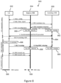
- Figure 8 illustrates a Radio link failure (RLF) warning for the assisting eNB 808 out-of-sync.
- RLF Radio link failure
- a reaction to a source eNB 904 out-of-sync is described.
- a RLF between the UE 902 and the source eNodeB 904 has occurred.
- the UE 902 stops transmission to the source eNodeB 904.
- a RLF warning is sent from the UE 902 to the source eNodeB 904 via the assisting eNodeB 908.
- the source eNodeB 904 sends a handover request to the assisting eNodeB 908.
- the assisting eNodeB 908 sends a handover acknowledgement to the source eNodeB 904.
- the source eNodeB 904 sends a RRC reconfiguration request via the assisting eNodeB 908 to the user equipment UE 902.
- the source eNodeB 904 stops RRC diversity and the assisting eNodeB 908 upgrades to the RRC anchor in a step 999 for the UE 902.
- the source eNodeB 904 sends a sequence number status transfer to the assisting eNodeB 908, and the UE 902 sends in a step 13 a RRC reconfiguration command to the assisting eNodeB 908.
- the assisting eNodeB 908 sends a UE context release message to the source eNodeB 904.
- RLF on the link to the source eNB 904 occurs and is registered within the UE 902. It will stop its transmission on this link and transmit an RLF warning indication towards the assisting eNB 908 (7) which will (since it is in RRC relaying mode) further forward this indication towards the source eNB 904.
- the source eNB 904 will than handover the UE 902 completely to the assisting eNB 908 since it can be sure the connection source 904-UE 902is lost. Therefore, it will send the handover request indication (8) to the assisting eNB 908, which is acknowledged (9) by the assisting eNB 908.
- source eNB 904 will send sequence number status transfer (12) to the assisting eNB 908 and forward buffered packets.
- the UE 902 will confirm the RRC reconfiguration to be solely connected to the assisting (now anchor) eNB 908 (13), and eventually the assisting eNB 908 will send the UE context release indication to the source eNB 904 (14).
- the terminal 802, 902 may select a set of configured links on which it sends the RLF-warning on. For example, it may send the RLF-warning to all cells or a subset of all configured links such as only on the source link.
- the terminal 802, 902 may even send the RLF-warning on the link for which the T310 has expired.
- the benefit of sending the RLF-warning on the link for which T310 has expired is that the concerned node 804, 808, 904, 908 may need to be informed about the expiration of T310.
- the expiration of T310 indicates that the downlink quality is poor however the uplink may still have sufficiently good quality allowing the RLF-warning to reach the concerned node 804, 808, 904, 908.
- RLF-reporting may be regarded to be modified with respect to legacy RLF reporting according to TS 36.331 V11.2.0 (2012-12) which may be directed to RFL reporting for a single connection between a terminal 802, 902 and an access node 804, 808, 904, 908.
- the UE 802, 902 stores RLF related information for the (single) link where the failure occurred and sends the report to E-UTRAN upon request. The report is overridden when another RLF occurs.
- the UE 802, 902 shall trigger the original RLF procedure as well as the original RLF report only if all links fail. So, this reporting can be modified to convey information about multiple links.
- CQI reports received for each link in the respective network node 804, 808, 904, 908 can be forwarded to another node 804, 808, 904, 908, which is also currently connected to the UE 802, 902.
- the source eNodeB 804, 904 may be associated with a connection quality degradation
- the CQI received by the source eNodeB 804, 904 may be transmitted to the assisting eNodeB 808, 908.
- the eNB 804, 808, 904, 908 may experience similar faults as the UE 802, 902 e.g. maximum number of resynch attempts reached, maximum number of scheduling requests reached or maximum number of RLC retransmission reached and then eNB 804, 808, 904, 908 could ask the UE 802, 902 to provide historic data about UE events and transmissions done. This functionality can be established with another request/response message exchange triggered by the eNB 804, 808, 904, 908 and transmitted via one of the maintained connections.
- E-UTRAN is able to quickly react upon these connectivity problems and adapt its system settings to improve the performance for the UE 802, 902 and the overall system, e.g. certain key performance indicators.
- this solution will allow an operator to understand the root cause for intermittent performance degradations in a radio network and especially understand if it is a network problem or a UE problem or both.
- the method will also work in rather poor conditions since only one out of several connections to the network need to work.
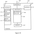
- the terminal 1002 comprises a determination unit 1009 adapted to determining whether a quality of at least one of the first connection and the second connection is degraded, and an acquiring unit 1011 adapted to acquire quality degradation information about the degradation of the quality of at least one of the first connection and the second connection based on the determination for adapting the mobile network based on the acquired quality degradation information.
- the terminal 1002 may comprise a determination unit 1009 adapted to determining whether a quality of at least one of the first connection and the second connection may be degraded, and an acquiring unit 1011 adapted to acquire quality degradation information about the degradation of the quality of at least one of the first connection and the second connection based on the determination particularly for adapting the mobile network.
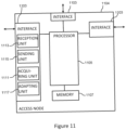
- the access node 1104 is adapted to perform a method according to embodiments described above and comprises respective functionality based units imbedded in respective physical units 1103, 1105, 1107 illustrated in Figure 11 .
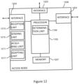
- the access node 1208 comprises an adapting unit 1217 adapted to adapt the mobile network based on acquired quality degradation information about a degradation of a quality of at least one of the connection and the another connection, the acquiring of the quality degradation information being based on a determination whether a quality of at least one of the connection and the another connection is degraded.
- the access node 1208 may comprise an adapting unit 1217 adapted to adapt the mobile network based on a quality of at least one of the connection and the another connection being degraded.
- the adapting unit 1217 unit may be adapted to perform the adaption based on acquired quality degradation information about a degradation of a quality of at least one of the connection and the another connection.
- the acquiring of the quality degradation information may be based on a determination whether a quality of at least one of the connection and the another connection is degraded.
- the access node 1208 may comprise an acquiring unit 1211 adapted to acquire the quality degradation information. In both latter described implementations, the access node 1208 may also comprise a determination unit 1209 adapted to determine whether the quality of at least one of the connection and the another connection may be degraded.
- the described functionality based units 1009 to 1015, 1109 to 1117, 1209 to 1217 for implementing the above described functionalities of the respective entity 1002, 1104, 1208 may be also realized in software and/or in hardware and software.
- suitable configured computer program code may be stored for implementing the above-described functionalities of the respective entity 1002, 1104 1208 in the memory 1007, 1107, 1207 of the respective above described entity 1002, 1104, 1208.
- the memory 1007, 1107, 1207 and the computer program code may form a computer program product.
- the computer program code may be also stored on a different memory loadable into the memory 1007, 1107, 1207 of the respective entity 1002, 1104, 1208.
- the computer program code may be also provided in a downloadable form, forming a further computer program product.
- the terminal is part of the mobile network.
- first connection and the second connection may be independent from one another and may comprise respective radio bearers to be established related to the data transmission.
- the first access node is referred in described embodiments as “Source eNB” and the first connection is labeled in Figure 4 by “anchor”.
- the second access node is referenced in described embodiments as “Assisting eNB”.
- the second connection is labeled in Figure 4 by "booster" It is noted that the target eNB described in connection with Figures 1 and 2 also represents an access node adapted to control the data transmission for the terminal.
- data are sent from the first access node to the terminal and data duplicates are sent from the second access node to the terminal.
- the first access node may have duplicated the respective data and hay have sent the data duplicates to the second access node.
- step of determining results in the first connection having failed wherein the step of adapting comprises:
- step of determining results in the first connection having failed wherein the step of adapting comprises:
- the first access node may initiate the handover of the terminal by sending a handover request to the second access node.
- the second access node may forward or relay the handover request to the terminal.
- the first access node may stop controlling the data transmission of the terminal.
- the latter may relate to stop RRC diversity.
- RRC diversity employed in the first access node may relate to a sending of data directly to the terminal and to a sending of duplicates of the data, which are sent by the first access node to the terminal, to the second access node for relaying them by the second access node to the terminal.
- stopping RRC diversity may refer to not duplicating the sent data anymore, thus maintaining only the direct connection to the terminal to keep a legacy functionality.
- the latter may relate to stopping RRC signal duplication and forwarding to the second access node.
- the system setting may relate to a characteristic of the first and/or second access node or may relate to a characteristic of a further access node of the mobile network.
- step of determining is performed by the terminal and comprises evaluating the quality of the first connection and evaluating the quality of the second connection.
- the step of evaluating of the quality of the first connection and the step of evaluating the quality of the second connection is performed independently of one another.
- the respective step of evaluating comprises evaluating a synchronization of the terminal with the respective access node with respect to the data transmission over the respective connection.
- step of determining comprises, particularly for each of the first and second connections, using a timer in the terminal and a counter in the terminal, the counter being associated with fulfillment of a condition, wherein a degradation of the quality of the respective connection is determined, if the timer expires, the timer being started after a predetermined number of the counter fulfillments of the condition, and the timer being stopped after a predetermined number of counter fulfillments of another condition.
- the step of determining comprises, particularly for each of the first and second connections, using a timer in the terminal and counters in the terminal, one counter being associated with fulfillment of a condition, wherein a degradation of the quality of the respective connection is determined, if the timer expires, the timer being started after a predetermined number of the counter fulfillments of the condition, and the timer being stopped after a predetermined number of another counter fulfillments of another condition.
- step of acquiring comprises sending by the second access node to the first access the quality degradation information.
- the latter embodiment may apply to the embodiment related to handing over the terminal and to the embodiment related to the handover combined with the transfer of the control capabilities.
- a method embodiment for adapting a mobile network wherein a terminal is connected to a first access node of the mobile network via a first connection and to a second access node via a second connection, wherein the first access node controls a data transmission for the terminal and wherein the second access node assists in the data transmission for the terminal, the method being performed by the terminal and comprising:
- a method embodiment for adapting a mobile network wherein a terminal is connected to a first access node of the mobile network via a first connection and to a second access node via a second connection, wherein the first access node controls a data transmission for the terminal and wherein the second access node assists in the data transmission for the terminal, the method being performed by the first access node and comprising:
- a method embodiment for adapting a mobile network wherein a terminal is connected to a first access node of the mobile network via a first connection and to a second access node via a second connection, wherein the first access node controls a data transmission for the terminal and wherein the second access node assists in the data transmission for the terminal, the method being performed by the second access node and comprising:
- a terminal embodiment for adapting a mobile network wherein the terminal is connected to a first access node of the mobile network via a first connection and to a second access node via a second connection, wherein the first access node controls a data transmission for the terminal and wherein the second access node assists in the data transmission for the terminal, the terminal comprising:
- the access node may be adapted to perform a method according to any one of embodiments 1 to 17 and 19.
- An access node embodiment for adapting a mobile network wherein a terminal is connected to the access node of the mobile network via a connection and to another access node via another connection, wherein the another access node controls a data transmission for the terminal and wherein the access node assists in the data transmission for the terminal, the access node comprising:
- the access node may be adapted to perform a method according to anyone of embodiments 1 to 17 and 19.
- a mobile network embodiment comprising a terminal according to embodiment 20, a first access node according to embodiment 21, and a second access node according to embodiment 22.
- a computer program which, when being executed by a processor, is adapted to carry out or control a method for handling a terminating circuit switched signaling service to a terminal in a mobile network according to any one of embodiments 1 to 19.
Landscapes
- Engineering & Computer Science (AREA)
- Computer Networks & Wireless Communication (AREA)
- Signal Processing (AREA)
- Mobile Radio Communication Systems (AREA)
Applications Claiming Priority (6)
| Application Number | Priority Date | Filing Date | Title |
|---|---|---|---|
| US201361754322P | 2013-01-18 | 2013-01-18 | |
| EP21191821.4A EP3975617B1 (de) | 2013-01-18 | 2014-01-17 | Anpassung eines mobilfunknetzes |
| PCT/EP2014/050868 WO2014111499A1 (en) | 2013-01-18 | 2014-01-17 | Adapting a mobile network |
| EP16204093.5A EP3217719B1 (de) | 2013-01-18 | 2014-01-17 | Anpassung eines mobilfunknetzes |
| EP14700715.7A EP2946596B1 (de) | 2013-01-18 | 2014-01-17 | Anpassung eines mobilfunknetzes |
| EP19161302.5A EP3515118B1 (de) | 2013-01-18 | 2014-01-17 | Anpassung eines mobilfunknetzes |
Related Parent Applications (5)
| Application Number | Title | Priority Date | Filing Date |
|---|---|---|---|
| EP14700715.7A Division EP2946596B1 (de) | 2013-01-18 | 2014-01-17 | Anpassung eines mobilfunknetzes |
| EP19161302.5A Division EP3515118B1 (de) | 2013-01-18 | 2014-01-17 | Anpassung eines mobilfunknetzes |
| EP16204093.5A Division EP3217719B1 (de) | 2013-01-18 | 2014-01-17 | Anpassung eines mobilfunknetzes |
| EP21191821.4A Division EP3975617B1 (de) | 2013-01-18 | 2014-01-17 | Anpassung eines mobilfunknetzes |
| EP21191821.4A Division-Into EP3975617B1 (de) | 2013-01-18 | 2014-01-17 | Anpassung eines mobilfunknetzes |
Publications (2)
| Publication Number | Publication Date |
|---|---|
| EP4583582A2 true EP4583582A2 (de) | 2025-07-09 |
| EP4583582A3 EP4583582A3 (de) | 2025-09-17 |
Family
ID=49989775
Family Applications (5)
| Application Number | Title | Priority Date | Filing Date |
|---|---|---|---|
| EP25166634.3A Pending EP4583582A3 (de) | 2013-01-18 | 2014-01-17 | Anpassung eines mobilen netzwerks |
| EP21191821.4A Active EP3975617B1 (de) | 2013-01-18 | 2014-01-17 | Anpassung eines mobilfunknetzes |
| EP14700715.7A Active EP2946596B1 (de) | 2013-01-18 | 2014-01-17 | Anpassung eines mobilfunknetzes |
| EP19161302.5A Active EP3515118B1 (de) | 2013-01-18 | 2014-01-17 | Anpassung eines mobilfunknetzes |
| EP16204093.5A Active EP3217719B1 (de) | 2013-01-18 | 2014-01-17 | Anpassung eines mobilfunknetzes |
Family Applications After (4)
| Application Number | Title | Priority Date | Filing Date |
|---|---|---|---|
| EP21191821.4A Active EP3975617B1 (de) | 2013-01-18 | 2014-01-17 | Anpassung eines mobilfunknetzes |
| EP14700715.7A Active EP2946596B1 (de) | 2013-01-18 | 2014-01-17 | Anpassung eines mobilfunknetzes |
| EP19161302.5A Active EP3515118B1 (de) | 2013-01-18 | 2014-01-17 | Anpassung eines mobilfunknetzes |
| EP16204093.5A Active EP3217719B1 (de) | 2013-01-18 | 2014-01-17 | Anpassung eines mobilfunknetzes |
Country Status (22)
| Country | Link |
|---|---|
| US (5) | US10631222B2 (de) |
| EP (5) | EP4583582A3 (de) |
| JP (1) | JP6029774B2 (de) |
| KR (1) | KR101689986B1 (de) |
| CN (3) | CN105191402B (de) |
| AU (1) | AU2014206876B2 (de) |
| BR (1) | BR112015017180B1 (de) |
| CA (1) | CA2898564C (de) |
| CL (1) | CL2015002021A1 (de) |
| DK (3) | DK3515118T3 (de) |
| ES (4) | ES3029874T3 (de) |
| HU (1) | HUE044533T2 (de) |
| IL (1) | IL239842B (de) |
| MA (1) | MA38263B1 (de) |
| MX (1) | MX348985B (de) |
| MY (1) | MY177868A (de) |
| NZ (1) | NZ710169A (de) |
| PL (3) | PL2946596T3 (de) |
| PT (1) | PT2946596T (de) |
| RU (1) | RU2618509C2 (de) |
| TR (1) | TR201906324T4 (de) |
| WO (1) | WO2014111499A1 (de) |
Families Citing this family (69)
| Publication number | Priority date | Publication date | Assignee | Title |
|---|---|---|---|---|
| JP6167471B2 (ja) * | 2012-03-08 | 2017-07-26 | ヤマハ株式会社 | 無線端末装置 |
| WO2013141147A1 (ja) * | 2012-03-19 | 2013-09-26 | 京セラ株式会社 | 移動通信システム及び移動通信方法 |
| JP5823939B2 (ja) * | 2012-09-13 | 2015-11-25 | 株式会社Nttドコモ | 移動通信システム、無線基地局及び移動局 |
| EP4583582A3 (de) * | 2013-01-18 | 2025-09-17 | Telefonaktiebolaget LM Ericsson (publ) | Anpassung eines mobilen netzwerks |
| US9930581B2 (en) * | 2013-01-22 | 2018-03-27 | Avago Technologies General Ip (Singapore) Pte. Ltd. | Addressing communication failure in multiple connection systems |
| KR20170012580A (ko) | 2013-02-28 | 2017-02-02 | 닛본 덴끼 가부시끼가이샤 | 무선 통신 시스템, 무선국, 무선 단말, 통신 제어 방법, 및 비일시적인 컴퓨터 가독 매체 |
| KR20140120806A (ko) * | 2013-04-04 | 2014-10-14 | 주식회사 케이티 | Small cell에서 RLF(Radio Link Failure)를 detection 하는 방법 및 장치 |
| GB2512659A (en) | 2013-04-05 | 2014-10-08 | Nec Corp | Communication system |
| EP3313135B1 (de) * | 2013-04-05 | 2020-05-06 | Kyocera Corporation | Koordination zwischen basisstationen für duale konnektivität in mobilfunk |
| ES2724239T3 (es) | 2013-04-16 | 2019-09-09 | Huawei Tech Co Ltd | Dispositivo y procedimiento de traspaso de célula |
| CN104349361B (zh) * | 2013-08-06 | 2019-05-17 | 上海诺基亚贝尔股份有限公司 | 用于无线资源控制连接的方法及装置 |
| US9930589B2 (en) * | 2013-09-09 | 2018-03-27 | Nokia Technologies Oy | Detection and recovery from loss of small cell connection |
| US9942820B2 (en) * | 2013-12-02 | 2018-04-10 | Apple Inc. | Systems and methods for cross-cell carrier aggregation for coverage balance improvement |
| CN104753627A (zh) * | 2013-12-26 | 2015-07-01 | 中兴通讯股份有限公司 | 多路径传输方法、系统及数据发送装置和数据接收装置 |
| US10306695B2 (en) * | 2014-01-31 | 2019-05-28 | Qualcomm Incorporated | Procedures for managing secondary eNB (SeNB) radio link failure (S-RLF) in dual connectivity scenarios |
| US10979945B2 (en) * | 2014-03-25 | 2021-04-13 | Sony Corporation | Device to reduce consumption of radio resources of a macrocell |
| JP6031555B2 (ja) * | 2014-05-13 | 2016-11-24 | 宏達國際電子股▲ふん▼有限公司 | 測定構成を処理する装置 |
| WO2016026508A1 (en) * | 2014-08-18 | 2016-02-25 | Nokia Solutions And Networks Oy | Method and apparatus for sending handover indication to assisting cell |
| US11089648B2 (en) * | 2015-01-30 | 2021-08-10 | Kyocera Corporation | User terminal for executing dual connectivity |
| EP3249974A4 (de) * | 2015-02-10 | 2018-01-24 | Huawei Technologies Co., Ltd. | Verfahren für endgerät zum aufbau einer verbindung, zweiter knoten, erstes endgerät und zweites endgerät |
| MY194317A (en) | 2015-02-13 | 2022-11-28 | Ericsson Telefon Ab L M | Multi-path transmission control protocol connections |
| KR20170128581A (ko) * | 2015-03-19 | 2017-11-22 | 노키아 솔루션스 앤드 네트웍스 오와이 | 모바일 라디오 통신 네트워크의 동작 검증 방법 |
| US9894702B2 (en) * | 2015-05-14 | 2018-02-13 | Intel IP Corporation | Performing primary cell functions in a secondary cell |
| US9894681B2 (en) | 2015-06-12 | 2018-02-13 | Ofinno Technologies, Llc | Uplink scheduling in a wireless device and wireless network |
| US10200177B2 (en) | 2015-06-12 | 2019-02-05 | Comcast Cable Communications, Llc | Scheduling request on a secondary cell of a wireless device |
| US9948487B2 (en) | 2015-06-15 | 2018-04-17 | Ofinno Technologies, Llc | Uplink resource allocation in a wireless network |
| US9723543B2 (en) | 2015-07-08 | 2017-08-01 | Blackberry Limited | Systems and methods for managing a UE-to-network relay |
| US11700555B2 (en) * | 2015-08-14 | 2023-07-11 | Qualcomm Incorporated | Mobility design for eMTC |
| KR102564318B1 (ko) | 2015-08-21 | 2023-08-07 | 삼성전자주식회사 | 무선 통신 시스템에서 다중 연결을 이용한 핸드오버를 지원하는 장치 및 방법 |
| KR102034401B1 (ko) * | 2015-10-05 | 2019-10-18 | 텔레폰악티에볼라겟엘엠에릭슨(펍) | 무선 통신 시스템에서 무선 디바이스와 서비스 노드 간의 무선 링크 문제 관리 |
| KR102460350B1 (ko) * | 2015-11-06 | 2022-10-28 | 삼성전자주식회사 | 통신 시스템에서 데이터 송수신 방법 및 장치 |
| CN107171820B (zh) * | 2016-03-08 | 2019-12-31 | 北京京东尚科信息技术有限公司 | 信息传输、发送、获取方法和装置 |
| US10959138B2 (en) * | 2016-03-30 | 2021-03-23 | Sharp Kabushiki Kaisha | Terminal apparatus, base station apparatus, communication method, and control method |
| CN107277879B (zh) * | 2016-04-01 | 2021-06-04 | 北京三星通信技术研究有限公司 | 一种支持无缝切换的方法及基站设备 |
| US10021617B2 (en) * | 2016-04-01 | 2018-07-10 | Lg Electronics Inc. | Method and apparatus for performing, by terminal in WLAN interworking operation, handover |
| WO2018029373A1 (en) * | 2016-08-11 | 2018-02-15 | Sony Corporation | Base station, user equipment and mobile telecommunicatons system method |
| WO2018029537A1 (en) | 2016-08-12 | 2018-02-15 | Telefonaktiebolaget Lm Ericsson (Publ) | Dynamic link selection |
| EP3764695B1 (de) * | 2016-09-22 | 2021-10-06 | Guangdong Oppo Mobile Telecommunications Corp., Ltd. | Verwaltung durch ein erstes netzgerät von einer verbindung zwischen einem endgerät und einem zweiten netzgerät gemäss der verbindungsqualität |
| CN106797648B (zh) * | 2016-11-04 | 2020-12-18 | 北京小米移动软件有限公司 | Rrc消息的发送方法及装置 |
| US10405231B2 (en) * | 2017-04-24 | 2019-09-03 | Motorola Mobility Llc | Switching between packet duplication operating modes |
| CN109245870B (zh) * | 2017-06-16 | 2021-12-28 | 华为技术有限公司 | 处理无线链路失败方法、终端设备和基站 |
| CN114125893A (zh) | 2017-08-11 | 2022-03-01 | 华为技术有限公司 | 一种测量方法、设备及系统 |
| CA3068640C (en) * | 2017-08-11 | 2022-05-03 | Guangdong Oppo Mobile Telecommunications Corp., Ltd. | Control method, node, and computer storage medium |
| US10757615B2 (en) | 2017-09-13 | 2020-08-25 | Comcast Cable Communications, Llc | Radio link failure information for PDCP duplication |
| US20190150014A1 (en) * | 2017-11-16 | 2019-05-16 | Nokia Technologies Oy | Early measurement reporting for cell access |
| RU2741582C1 (ru) * | 2018-01-11 | 2021-01-27 | Телефонактиеболагет Лм Эрикссон (Пабл) | Обслуживание линии радиосвязи, включающей в себя множество несущих восходящей линии связи |
| CN110099417B (zh) | 2018-01-30 | 2021-07-23 | 中国移动通信有限公司研究院 | 切换方法、信息交互方法、设备及计算机可读存储介质 |
| WO2019157706A1 (en) * | 2018-02-14 | 2019-08-22 | Nokia Shanghai Bell Co., Ltd. | Methods and apparatuses for prioritized random access during handover |
| CN110278574B (zh) * | 2018-03-16 | 2021-06-04 | 维沃移动通信有限公司 | 测量方法、测量配置方法、终端及网络设备 |
| CN110351790A (zh) * | 2018-04-04 | 2019-10-18 | 惠州Tcl移动通信有限公司 | 基于双连接的通信切换方法及装置 |
| US11343697B2 (en) * | 2018-05-16 | 2022-05-24 | Comcast Cable Communications, Llc | Systems and methods for network device management |
| WO2019240770A1 (en) * | 2018-06-12 | 2019-12-19 | Nokia Technologies Oy | Two-step addition of a primary-secondary cell, pscell, in a multi-connected handover |
| CN110830527A (zh) * | 2018-08-07 | 2020-02-21 | 阿里巴巴集团控股有限公司 | 一种网络间数据通信的方法、装置及数据通信系统 |
| US11895514B2 (en) | 2018-10-10 | 2024-02-06 | Telefonaktiebolaget Lm Ericsson (Publ) | Method and apparatus used in transmission reliability |
| CN111132203B (zh) * | 2018-10-31 | 2021-11-16 | 维沃移动通信有限公司 | 一种处理方法及终端 |
| US11006342B2 (en) * | 2018-11-12 | 2021-05-11 | Qualcomm Incorporated | Handover techniques in wireless communications |
| US10667192B1 (en) | 2018-11-12 | 2020-05-26 | Qualcomm Incorporated | Handover techniques in wireless communications |
| CN113661775B (zh) | 2019-02-12 | 2024-08-16 | 交互数字专利控股公司 | 用于侧链路无线电链路监视和确定无线电链路故障的方法 |
| WO2020263283A1 (en) * | 2019-06-28 | 2020-12-30 | Nokia Technologies Oy | Early data transmission for dual connectivity or carrier aggregation |
| CN112218344B (zh) * | 2019-07-12 | 2022-12-30 | 华为技术有限公司 | 一种通信方法及装置 |
| CN112399497B (zh) * | 2019-08-15 | 2024-07-23 | 华为技术有限公司 | 通信方法和通信装置 |
| WO2021192836A1 (ja) * | 2020-03-23 | 2021-09-30 | シャープ株式会社 | 基地局、端末、通信システム、および制御方法 |
| US11277318B2 (en) * | 2020-04-30 | 2022-03-15 | Accenture Global Solutions Limited | Analyzing a communication network device, based on capacity analyses associated with decommissioning the communication network device, to determine next actions |
| EP4140246A1 (de) * | 2020-05-28 | 2023-03-01 | Google LLC | Anpassung von funkzugangsnetzwerkverbindungen auf basis von kommunikationsfehlern |
| US11438273B2 (en) | 2020-07-20 | 2022-09-06 | Altiostar Networks, Inc. | Real-time processing in wireless communications systems |
| US12289620B2 (en) * | 2021-07-13 | 2025-04-29 | Samsung Electronics Co., Ltd. | Method and device of enabling multi-connectivity in wireless network for improving QOS of UE |
| US12471183B2 (en) * | 2022-07-07 | 2025-11-11 | Samsung Electronics Co., Ltd. | Method and apparatus for inter-UE coordination in SL CA |
| US20240389072A1 (en) * | 2023-05-16 | 2024-11-21 | Cisco Technology, Inc. | Automatic tracking area identity list generation in an access and mobility management function in 5g deployments |
| CN116887338B (zh) * | 2023-09-06 | 2023-12-08 | 南京欣网通信科技股份有限公司 | 基于大数据的5g移动网络实时调整方法 |
Family Cites Families (42)
| Publication number | Priority date | Publication date | Assignee | Title |
|---|---|---|---|---|
| US6507561B1 (en) * | 1997-03-12 | 2003-01-14 | Worldcom, Inc. | Telecommunications network distributed restoration method and system |
| US6728216B1 (en) * | 1998-02-27 | 2004-04-27 | Advanced Micro Devices, Inc. | Arrangement in a network repeater for monitoring link integrity and selectively down shifting link speed based on local configuration signals |
| US6662019B2 (en) * | 2000-12-21 | 2003-12-09 | Lucent Technologies Inc. | Power control and transmission rate parameters of a secondary channel in a wireless communication system |
| US7742990B2 (en) * | 2002-03-29 | 2010-06-22 | Ntt Docomo, Inc. | Communication control method in connection-oriented communication, related transfer device, and billing management device |
| DE60311155T2 (de) * | 2003-08-19 | 2007-10-18 | Ntt Docomo Inc. | Genaue steuerung von informationsübertragungen in ad-hoc netzwerken |
| CN100370880C (zh) * | 2004-11-22 | 2008-02-20 | 华为技术有限公司 | 一种在切换后保持睡眠状态的方法 |
| US7899495B2 (en) | 2006-07-14 | 2011-03-01 | Qualcomm Incorporated | Methods and apparatus for supporting multiple connections |
| US8923321B2 (en) * | 2006-07-28 | 2014-12-30 | Motorola Mobility Llc | Apparatus and method for handling control channel reception/decoding failure in a wireless VoIP communication system |
| AR065711A1 (es) | 2007-03-13 | 2009-06-24 | Interdigital Tech Corp | Un procedimiento de reseleccion de celula para comunicaciones inalambricas |
| AR066248A1 (es) | 2007-04-23 | 2009-08-05 | Interdigital Tech Corp | Conexion radial y manipulacion de falla de recepcion |
| WO2008156321A2 (en) * | 2007-06-19 | 2008-12-24 | Lg Electronics Inc. | Enhancement of lte random access procedure |
| US8391906B2 (en) * | 2007-11-16 | 2013-03-05 | Qualcomm Incorporated | Basing neighbor list updates on a radio link failure |
| KR101435835B1 (ko) * | 2008-03-31 | 2014-08-29 | 엘지전자 주식회사 | 단말기 및 이것의 채널 버퍼링 방법 |
| US20100080116A1 (en) * | 2008-09-29 | 2010-04-01 | Qualcomm Incorporated | Re-establishing a radio resource control connection with a non-prepared base station |
| US9271204B2 (en) | 2008-11-17 | 2016-02-23 | Qualcomm Incorporated | Mobility management based on radio link failure reporting |
| CN101815314A (zh) * | 2009-02-20 | 2010-08-25 | 华为技术有限公司 | 发现无线网络问题的方法、装置及系统 |
| CN104917598B (zh) * | 2009-03-16 | 2018-12-11 | Lg电子株式会社 | 支持载波聚合的方法和设备 |
| US8923245B2 (en) * | 2009-03-25 | 2014-12-30 | Lg Electronics Inc. | Method and apparatus for handover in a mobile communication system |
| US8553547B2 (en) * | 2009-03-30 | 2013-10-08 | Broadcom Corporation | Systems and methods for retransmitting packets over a network of communication channels |
| EP2448343A4 (de) * | 2009-06-22 | 2015-07-22 | Sharp Kk | Kommunikationssystem, mobilstation, basisstation und kommunikationsverfahren |
| CN101959262B (zh) | 2009-07-15 | 2015-07-22 | 中兴通讯股份有限公司 | 切换失败指示信息的通知方法与装置 |
| US20110170422A1 (en) * | 2010-01-08 | 2011-07-14 | Rose Qingyang Hu | System and method for coordinated multi-point network operation to reduce radio link failure |
| JP4970559B2 (ja) * | 2010-01-21 | 2012-07-11 | 株式会社エヌ・ティ・ティ・ドコモ | 移動通信システム、ネットワーク装置及び移動通信方法 |
| JP2011166372A (ja) | 2010-02-08 | 2011-08-25 | Ntt Docomo Inc | 移動通信方法及び無線基地局 |
| CN106160992B (zh) | 2010-02-12 | 2020-07-03 | 交互数字专利控股公司 | 增强无线发射/接收单元的小区边缘性能的方法及网络 |
| JP5447103B2 (ja) * | 2010-03-31 | 2014-03-19 | 富士通株式会社 | 無線接続のための方法、装置及びシステム |
| US20120002174A1 (en) * | 2010-06-30 | 2012-01-05 | Shin-Gwo Shiue | Light source system of pico projector |
| JP5878935B2 (ja) | 2011-02-17 | 2016-03-08 | テレフオンアクチーボラゲット エル エム エリクソン(パブル) | 無線アクセス技術間の測定結果を報告するための方法及び装置 |
| US9661510B2 (en) * | 2012-03-30 | 2017-05-23 | Mediatek Inc. | Failure event report extension for inter-RAT radio link failure |
| CN103430501A (zh) * | 2011-04-01 | 2013-12-04 | 英特尔公司 | 用于无线通信网络中的灵活秩自适应的方法、设备和系统 |
| US9119122B2 (en) * | 2011-04-12 | 2015-08-25 | Telefonaktiebolaget L M Ericsson (Publ) | Apparatus, method, and computer program product for adjusting handover parameters |
| KR20120122819A (ko) * | 2011-04-30 | 2012-11-07 | 주식회사 팬택 | 무선통신 시스템에서 무선 연결을 재설정하는 장치 및 방법 |
| US9510259B2 (en) | 2011-11-10 | 2016-11-29 | Telefonaktiebolaget Lm Ericsson (Publ) | Methods and arrangement for handling a data transferral in a cellular network |
| CN103179601B (zh) * | 2011-12-23 | 2019-07-23 | 北京三星通信技术研究有限公司 | 一种检测无线链路失败或切换失败原因的方法 |
| CN102685855B (zh) * | 2012-05-14 | 2014-11-19 | 中国联合网络通信集团有限公司 | 小区驻留方法和用户设备 |
| EP2874460B1 (de) | 2012-07-31 | 2019-01-23 | Huawei Technologies Co., Ltd. | Verfahren und vorrichtung zur wiederherstellung nach funkverbindungsausfällen |
| KR102044019B1 (ko) * | 2012-08-03 | 2019-12-02 | 삼성전자주식회사 | 이동성 매개변수 조정 방법 및 장치 |
| US20140120930A1 (en) * | 2012-10-31 | 2014-05-01 | Nokia Siemens Networks Oy | Method, Apparatus, Computer Program Product and System for Communicating Predictions |
| EP4583582A3 (de) * | 2013-01-18 | 2025-09-17 | Telefonaktiebolaget LM Ericsson (publ) | Anpassung eines mobilen netzwerks |
| WO2015023067A1 (ko) * | 2013-08-12 | 2015-02-19 | 삼성전자 주식회사 | 다중 기지국 연결 기반의 무선 통신 시스템에서의 무선 링크 실패 처리 방법 및 그 장치 |
| US9572171B2 (en) * | 2013-10-31 | 2017-02-14 | Intel IP Corporation | Systems, methods, and devices for efficient device-to-device channel contention |
| CN117098176A (zh) * | 2022-05-11 | 2023-11-21 | 华为技术有限公司 | 通信方法及装置 |
-
2014
- 2014-01-17 EP EP25166634.3A patent/EP4583582A3/de active Pending
- 2014-01-17 US US14/761,770 patent/US10631222B2/en active Active
- 2014-01-17 MX MX2015009235A patent/MX348985B/es active IP Right Grant
- 2014-01-17 JP JP2015553086A patent/JP6029774B2/ja active Active
- 2014-01-17 HU HUE16204093 patent/HUE044533T2/hu unknown
- 2014-01-17 CN CN201480016854.7A patent/CN105191402B/zh active Active
- 2014-01-17 AU AU2014206876A patent/AU2014206876B2/en active Active
- 2014-01-17 PL PL14700715T patent/PL2946596T3/pl unknown
- 2014-01-17 PT PT147007157T patent/PT2946596T/pt unknown
- 2014-01-17 KR KR1020157022265A patent/KR101689986B1/ko active Active
- 2014-01-17 PL PL19161302T patent/PL3515118T3/pl unknown
- 2014-01-17 RU RU2015134536A patent/RU2618509C2/ru active
- 2014-01-17 EP EP21191821.4A patent/EP3975617B1/de active Active
- 2014-01-17 TR TR2019/06324T patent/TR201906324T4/tr unknown
- 2014-01-17 ES ES21191821T patent/ES3029874T3/es active Active
- 2014-01-17 MY MYPI2015702288A patent/MY177868A/en unknown
- 2014-01-17 EP EP14700715.7A patent/EP2946596B1/de active Active
- 2014-01-17 DK DK19161302.5T patent/DK3515118T3/da active
- 2014-01-17 NZ NZ710169A patent/NZ710169A/en unknown
- 2014-01-17 CN CN202411988573.XA patent/CN119835712A/zh active Pending
- 2014-01-17 CN CN201911377569.9A patent/CN111586775B/zh active Active
- 2014-01-17 EP EP19161302.5A patent/EP3515118B1/de active Active
- 2014-01-17 WO PCT/EP2014/050868 patent/WO2014111499A1/en not_active Ceased
- 2014-01-17 ES ES14700715.7T patent/ES2628296T3/es active Active
- 2014-01-17 DK DK14700715.7T patent/DK2946596T3/en active
- 2014-01-17 ES ES16204093T patent/ES2733578T3/es active Active
- 2014-01-17 BR BR112015017180-0A patent/BR112015017180B1/pt active IP Right Grant
- 2014-01-17 DK DK16204093.5T patent/DK3217719T3/da active
- 2014-01-17 CA CA2898564A patent/CA2898564C/en active Active
- 2014-01-17 ES ES19161302T patent/ES2895156T3/es active Active
- 2014-01-17 EP EP16204093.5A patent/EP3217719B1/de active Active
- 2014-01-17 PL PL16204093T patent/PL3217719T3/pl unknown
-
2015
- 2015-07-08 IL IL239842A patent/IL239842B/en active IP Right Grant
- 2015-07-10 MA MA38263A patent/MA38263B1/fr unknown
- 2015-07-20 CL CL2015002021A patent/CL2015002021A1/es unknown
-
2020
- 2020-03-11 US US16/815,577 patent/US10959151B2/en active Active
-
2021
- 2021-02-08 US US17/170,078 patent/US11570681B2/en active Active
-
2022
- 2022-12-28 US US18/089,644 patent/US11985564B2/en active Active
-
2024
- 2024-04-11 US US18/632,975 patent/US12543094B2/en active Active
Also Published As
Similar Documents
| Publication | Publication Date | Title |
|---|---|---|
| US12543094B2 (en) | Adapting a mobile network | |
| CN102804850B (zh) | 在无线通信系统中在切换失败时记录测量结果的方法 | |
| US9544822B2 (en) | Handover signaling assistance | |
| HK1219198B (zh) | 适应移动网络 |
Legal Events
| Date | Code | Title | Description |
|---|---|---|---|
| PUAI | Public reference made under article 153(3) epc to a published international application that has entered the european phase |
Free format text: ORIGINAL CODE: 0009012 |
|
| STAA | Information on the status of an ep patent application or granted ep patent |
Free format text: STATUS: THE APPLICATION HAS BEEN PUBLISHED |
|
| AC | Divisional application: reference to earlier application |
Ref document number: 2946596 Country of ref document: EP Kind code of ref document: P Ref document number: 3217719 Country of ref document: EP Kind code of ref document: P Ref document number: 3515118 Country of ref document: EP Kind code of ref document: P Ref document number: 3975617 Country of ref document: EP Kind code of ref document: P |
|
| AK | Designated contracting states |
Kind code of ref document: A2 Designated state(s): AL AT BE BG CH CY CZ DE DK EE ES FI FR GB GR HR HU IE IS IT LI LT LU LV MC MK MT NL NO PL PT RO RS SE SI SK SM TR |
|
| REG | Reference to a national code |
Ref country code: DE Ref legal event code: R079 Free format text: PREVIOUS MAIN CLASS: H04W0036040000 Ipc: H04W0036000000 |
|
| PUAL | Search report despatched |
Free format text: ORIGINAL CODE: 0009013 |