EP3217719B1 - Anpassung eines mobilfunknetzes - Google Patents
Anpassung eines mobilfunknetzes Download PDFInfo
- Publication number
- EP3217719B1 EP3217719B1 EP16204093.5A EP16204093A EP3217719B1 EP 3217719 B1 EP3217719 B1 EP 3217719B1 EP 16204093 A EP16204093 A EP 16204093A EP 3217719 B1 EP3217719 B1 EP 3217719B1
- Authority
- EP
- European Patent Office
- Prior art keywords
- link
- enodeb
- user equipment
- access node
- connection
- Prior art date
- Legal status (The legal status is an assumption and is not a legal conclusion. Google has not performed a legal analysis and makes no representation as to the accuracy of the status listed.)
- Active
Links
- 238000000034 method Methods 0.000 claims description 136
- 230000005540 biological transmission Effects 0.000 claims description 131
- 238000005259 measurement Methods 0.000 claims description 38
- 230000011664 signaling Effects 0.000 claims description 24
- 238000004590 computer program Methods 0.000 claims description 22
- 230000009977 dual effect Effects 0.000 claims description 18
- 230000004044 response Effects 0.000 claims description 9
- 230000000977 initiatory effect Effects 0.000 claims 1
- 230000015556 catabolic process Effects 0.000 description 94
- 238000006731 degradation reaction Methods 0.000 description 94
- 238000010586 diagram Methods 0.000 description 13
- 238000012360 testing method Methods 0.000 description 12
- 238000004891 communication Methods 0.000 description 11
- 238000011156 evaluation Methods 0.000 description 8
- 230000001960 triggered effect Effects 0.000 description 7
- 238000006243 chemical reaction Methods 0.000 description 6
- 238000012546 transfer Methods 0.000 description 6
- 230000002776 aggregation Effects 0.000 description 4
- 238000004220 aggregation Methods 0.000 description 4
- 230000006399 behavior Effects 0.000 description 4
- 230000008901 benefit Effects 0.000 description 4
- 230000007774 longterm Effects 0.000 description 4
- 238000005516 engineering process Methods 0.000 description 3
- 230000001360 synchronised effect Effects 0.000 description 3
- 230000004931 aggregating effect Effects 0.000 description 2
- 230000009286 beneficial effect Effects 0.000 description 2
- 230000008859 change Effects 0.000 description 2
- 230000006870 function Effects 0.000 description 2
- 230000006872 improvement Effects 0.000 description 2
- 238000007726 management method Methods 0.000 description 2
- 238000012986 modification Methods 0.000 description 2
- 230000004048 modification Effects 0.000 description 2
- 238000012544 monitoring process Methods 0.000 description 2
- 238000013468 resource allocation Methods 0.000 description 2
- 238000013024 troubleshooting Methods 0.000 description 2
- 230000006978 adaptation Effects 0.000 description 1
- 238000013459 approach Methods 0.000 description 1
- 230000001413 cellular effect Effects 0.000 description 1
- 238000007405 data analysis Methods 0.000 description 1
- 230000003247 decreasing effect Effects 0.000 description 1
- 238000001514 detection method Methods 0.000 description 1
- 230000006866 deterioration Effects 0.000 description 1
- 238000005562 fading Methods 0.000 description 1
- 208000018910 keratinopathic ichthyosis Diseases 0.000 description 1
- 238000010295 mobile communication Methods 0.000 description 1
- 230000008450 motivation Effects 0.000 description 1
- 238000011084 recovery Methods 0.000 description 1
- 208000000649 small cell carcinoma Diseases 0.000 description 1
- 239000007787 solid Substances 0.000 description 1
Images


Classifications
-
- H—ELECTRICITY
- H04—ELECTRIC COMMUNICATION TECHNIQUE
- H04W—WIRELESS COMMUNICATION NETWORKS
- H04W36/00—Hand-off or reselection arrangements
- H04W36/24—Reselection being triggered by specific parameters
- H04W36/30—Reselection being triggered by specific parameters by measured or perceived connection quality data
- H04W36/305—Handover due to radio link failure
-
- H—ELECTRICITY
- H04—ELECTRIC COMMUNICATION TECHNIQUE
- H04W—WIRELESS COMMUNICATION NETWORKS
- H04W36/00—Hand-off or reselection arrangements
- H04W36/0005—Control or signalling for completing the hand-off
- H04W36/0055—Transmission or use of information for re-establishing the radio link
-
- H—ELECTRICITY
- H04—ELECTRIC COMMUNICATION TECHNIQUE
- H04W—WIRELESS COMMUNICATION NETWORKS
- H04W36/00—Hand-off or reselection arrangements
- H04W36/0005—Control or signalling for completing the hand-off
- H04W36/0055—Transmission or use of information for re-establishing the radio link
- H04W36/0069—Transmission or use of information for re-establishing the radio link in case of dual connectivity, e.g. decoupled uplink/downlink
- H04W36/00695—Transmission or use of information for re-establishing the radio link in case of dual connectivity, e.g. decoupled uplink/downlink using split of the control plane or user plane
-
- H—ELECTRICITY
- H04—ELECTRIC COMMUNICATION TECHNIQUE
- H04W—WIRELESS COMMUNICATION NETWORKS
- H04W36/00—Hand-off or reselection arrangements
- H04W36/24—Reselection being triggered by specific parameters
- H04W36/30—Reselection being triggered by specific parameters by measured or perceived connection quality data
-
- H—ELECTRICITY
- H04—ELECTRIC COMMUNICATION TECHNIQUE
- H04W—WIRELESS COMMUNICATION NETWORKS
- H04W36/00—Hand-off or reselection arrangements
- H04W36/0005—Control or signalling for completing the hand-off
- H04W36/0055—Transmission or use of information for re-establishing the radio link
- H04W36/0064—Transmission or use of information for re-establishing the radio link of control information between different access points
-
- H—ELECTRICITY
- H04—ELECTRIC COMMUNICATION TECHNIQUE
- H04W—WIRELESS COMMUNICATION NETWORKS
- H04W36/00—Hand-off or reselection arrangements
- H04W36/04—Reselecting a cell layer in multi-layered cells
-
- H—ELECTRICITY
- H04—ELECTRIC COMMUNICATION TECHNIQUE
- H04W—WIRELESS COMMUNICATION NETWORKS
- H04W36/00—Hand-off or reselection arrangements
- H04W36/24—Reselection being triggered by specific parameters
- H04W36/30—Reselection being triggered by specific parameters by measured or perceived connection quality data
- H04W36/302—Reselection being triggered by specific parameters by measured or perceived connection quality data due to low signal strength
Definitions
- the present disclosure relates to telecommunications and in particular to methods for adapting a mobile network. Nodes, a communication system, computer programs, and computer program products are also described.
- LTE Long Term Evolution
- UMTS Evolved Universal Terrestrial Radio Access Network
- E-UTRAN Evolved Universal Terrestrial Radio Access Network
- LTE is used as an example technology where the embodiments are suitable, and using LTE in the description therefore is particularly useful for understanding the problem and solutions solving the problem.
- LTE Mobility is described in the following.
- Radio Resource Control (Third Generation Partnership Project (3GPP) Technical Specification (TS) 36.331, e.g. V10.8.5 (2013-01)) is the main signaling protocol for configuring, re-configuring and general connection handling in the LTE radio access network (E-UTRAN).
- RRC controls many functions such as connection setup, mobility, measurements, radio link failure and connection recovery. These functions are of relevance for the present disclosure, and are therefore described in some further detail below.
- a UE in LTE can be in two RRC states: RRC_CONNECTED and RRC_IDLE.
- RRC_CONNECTED state mobility is network-controlled based on e.g. measurements provided by the UE. I.e. the network decides when and to which cell an UE should be handed over, based on e.g. measurements provided by the UE.
- the network i.e. the LTE radio base station (called evolved Node Base station (eNodeB or eNB), respectively, in E-UTRAN) configures various measurement events, thresholds etc. based on which the UE then sends reports to the network, such that the network can make a wise decision to hand over the UE to a stronger cell as the UE moves away from the present cell.
- eNodeB or eNB evolved Node Base station
- FIG. 1 illustrates a LTE RRC handover procedure according to 3GPP TS 36.300 , e.g. V11.4.0 (2013-01), Fig. 10.1.2.1.1-1.
- Fig. 1 illustrates a LTE RRC handover procedure.
- a UE 102 is connected to a source eNodeB 104 of a LTE radio access network, which is controlled by a Mobility Management Entity (MME) 106 of a packet switched domain of a core network.
- MME Mobility Management Entity
- a target eNodeB 108 is controlled by the MME 106.
- the user equipment 102 is exchanging data with a serving gateway 110 of the core network.
- MME Mobility Management Entity
- the user equipment 102 is handed over from the source eNodeB 102 to the target eNodeB 108 of the radio access network.
- Corresponding user data signaling is indicated by dashed arrows.
- L3 control signaling is indicated by dotted dashed arrows, and L1/L2 control signaling is indicated by solid arrows.
- the source eNodeB 104 sends in a first step 1 management control information to the user equipment 102, which in turn sends corresponding measurement reports in a step 2 to the source eNodeB 104.
- the source eNodeB 104 performs in a step 3 a handover decision, and sends a handover request in a step 4 to the target eNodeB 108.
- the target eNodeB 108 sends a handover request acknowledgement in a step 6 to the source eNodeB 102, which initiates a RRC connection reconfiguration in a step 7 towards the UE 100.
- FIG. 2 illustrates a simplified picture of the parts of the LTE Handover (HO) procedure relevant for the disclosure.
- the HO command is in fact prepared in the Target eNB, but the message transmitted via the Source eNB. I.e. the UE sees that the message comes from the Source eNB.
- a mobile network 200 comprises a source eNodeB 204 and a target eNodeB 208.
- a UE 202 is connected to the source eNodeB 204.
- a step 210 in which a measurement configuration is sent from the source eNodeB 204 to the user equipment 202, the user equipment 202 performs in a step 212 an A3 event in which a signal strength or signal quality of the target eNodeB 208 may be detected to be better compared to a signal strength or signal quality of the source eNodeB 204, respectively, and accordingly reports in a step 214 a measurement report to the source eNodeB 204.
- the source eNodeB 204 sends a handover request in a step 218 to the target eNodeB 208, which in turn sends a handover acknowledgement in a step 220 to the source eNodeB 204.
- the source eNodeB 204 then sends in a step 222 a handover command to the user equipment 202, which performs in a step 224 a random access procedure in which dedicated preambles are submitted to the target eNodeB 208.
- Further arrows 226-230 relate to a completion of the handover procedure.
- an uplink (UL) grant and a Tracking Area (TA) may be sent from the target eNodeB 208 to the UE 202.
- a HO confirm may be sent from the UE 202 to the target eNodeB 208.
- a Release context may be sent from the target eNodeB 208 to the source eNodeB 204.
- the steps 210, 214, 216, 218, 220, 222, 224 correspond to the steps 1, 2, 3, 4, 6, 7, and 11 in Fig. 1 .
- UE-based cell-selection where a nomadic UE 102, 202 selects the "best" cell to camp on, based e.g. on various specified criteria and parameters that are broadcasted in the cells. For example, various cells or frequency layers could be prioritized over other, such that the UE 102, 202 tries to camp on a particular cell as long as the measured quality of a beacon or pilot in that cell is a threshold better than some other beacon or pilot received from other cells.
- the present disclosure is primarily focusing on problems associated with network-controlled mobility as described above, i.e. for an LTE UE in RRC_CONNECTED state.
- the problems associated with failing handovers are therefore described in further detail below.
- a RRC_CONNECTED UE 102, 202 In a regular situation, and when a RRC_CONNECTED UE 102, 202 is moving out from the coverage of a first cell (also called source cell), it should be handed over to a neighboring cell (also called target cell or second cell) before loosing the connection to the first cell. I.e. it is desirable that the connection is maintained without no or minimal disruption throughout the handover, such that the end-user is unaware of the ongoing handover. In order to succeed with this, it is necessary that
- the UE 102, 202 must finally succeed in establishing a connection to the target cell, which in LTE requires a successful random access request in the target cell, and a subsequent HO complete message.
- specifications may differ somewhat in the naming of messages. This does not limit the applicability of the present disclosure.
- the handover command labeled as HO Command in the step 222 of Fig.2 corresponds to the RRC Configuration Reconfiguration of the step 7 of Fig.1
- the handover confirm message of the step 228 of Fig. 2 corresponds to the RRC Configuration Reconfiguration Complete of the step 11 of Fig. 1 .
- the exemplified measurement report is triggered by a so called A3 event in the step 212 which, in short, corresponds to the scenario in which a neighbor cell is found to be an offset better than the current serving cell. It should be noted that there are multiple events that can trigger a report.
- a UE102, 202 looses coverage to the cell that the UE 102, 202 is currently connected to. This could occur in a situation when a UE 102, 202 enters a fading dip, or that a handover was needed as described above, but the handover failed for one or another reason. This is particularly true if the "handover region" is very short.
- the radio link quality e.g. on the physical layer as described in 3GPP TS 36.300 , e.g. V11.4.0 (2013-01), TS 36.331, e.g. V11.2.0 (2013-01), and TS 36.133, e.g.
- the UE 102, 202 itself is able to declare a radio link failure and autonomously start a RRC re-establishment procedure. If the re-establishment is successful, which depends, among other things, if the selected cell and the eNB 104, 108, 204, 208 controlling that cell was prepared to maintain the connection to the UE 102, 202, then the connection between the UE 102, 202 and the eNB 104, 108, 204, 208 can resume.
- a failure of a re-establishment means that the UE 102, 202 goes to RRC_IDLE and the connection is released. To continue a communication, a brand new RRC connection has then to be requested and established.
- Dual connectivity is a feature defined from the UE perspective wherein the UE may simultaneously receive and transmit to at least two different network points.
- the at least two network points may be connected to one another via a backhaul link such that a UE may be enabled to communicate with one of the network points via the other network point.
- Dual connectivity is one of the features that are being standardized within the umbrella work of small cell enhancements within 3GPP Release 12 (Rel-12).
- Dual connectivity is defined for the case when the aggregated network points operate on the same or separate frequency.
- Each network point that the UE is aggregating may define a stand-alone cell or it may not define a stand-alone cell.
- the term "stand-alone cell" may particularly denote that each network point, hence each cell, may represent a separate cell from a perspective of a UE.
- network points not defining a stand-alone cell may be regarded from a perspective of a UE as one same cell. It is further foreseen that from the UE perspective the UE may apply some form of Time Division Multiplex (TDM) scheme between the different network points that the UE is aggregating. This implies that the communication on the physical layer to and from the different aggregated network points may not be truly simultaneous.
- TDM Time Division Multiplex
- Dual connectivity as a feature bears many similarities with carrier aggregation and coordinated multi-point (CoMP).
- the main differentiating factor is that dual connectivity is designed considering a relaxed backhaul and less stringent requirements on synchronization requirements between the network points. This is in contrast to carrier aggregation and CoMP, wherein tight synchronization and a low-delay backhaul are assumed between connected network points.
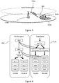
- Figure 3 illustrates the feature of dual connectivity of a UE 302 to an anchor 304a and a booster 304b.
- a UE 302 in dual connectivity maintains simultaneous connections 334a, 334b to anchor and booster nodes 304a, 304b.
- the anchor node 304a terminates the control plane connection towards the UE 302 and is thus the controlling node of the UE 302.
- the UE 302 also reads system information from the anchor 304a. In Fig. 3 , the system information and a spatial availability thereof are indicated by a dashed circle.
- the UE 302 may be connected to one or several booster nodes 304b for added user plane support.
- the term "booster" may denote that a performance of a UE in terms of its data peak rate may be improved, since user plane data may be additionally transmitted via the booster.
- a transmission frequency employed by the anchor may be different from a transmission frequency employed by the booster.
- the anchor and booster roles are defined from a UE 302 point of view. This means that a node that acts as an anchor 304a to one UE 302 may act as booster 304b to another UE 302. Similarly, though the UE 302 reads the system information from the anchor node 304a, a node acting as a booster 304b to one UE 302, may or may not distribute system information to another UE 302.
- Figure 4 illustrates a control and user plane termination in an anchor node and a booster node.
- This protocol architecture may represent an exemplary protocol termination compliant with dual connectivity and RRC diversity.
- the protocol architecture shown in Figure 4 is proposed as a way forward for realizing dual connectivity in LTE Rel-12 in deployments with relaxed backhaul requirements.
- PDCP Packet Data Convergence Protocol
- RLC Radio Link Control
- MPTCP Multipath Transmission Control Protocol
- NAS may represent a Non Access Stratum protocol layer
- RLC Radio Resource Control protocol layer
- MAC may represent Medium Access Control protocol layer
- PHYS Packet Data Convergence Protocol
- RRC is terminated in the anchor node, and PDCP is available both for the anchor node and the booster node.
- a problem may relate to handover failures and radio link failures for scenarios in which a UE is connected to one network point, hence one cell.
- handover and radio link failure robustness is described.
- Macro cells ensure large coverage with cells encompassing large areas, while micro-, pico- and even femto-cells are deployed in hot-spot areas where there is a large demand for capacity.
- Those cells typically provide connectivity in a much smaller area, but by adding additional cells (and radio base-stations controlling those cells), capacity is increased as the new cells off-load the macro cells.
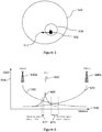
- Figure 5 illustrates a UE 502 moving out from a pico cell area of a pico cell 538 into macro cell area of a macro cell 540.
- a movement direction of the user equipment 502 is indicated by an arrow 542.
- This figure may illustrate a typical scenario for a handover of a UE 502.
- the different "layers" of cells can be deployed on the same carrier (i.e. in a reuse-1 fashion in which all neighboring cells may use the same frequency), the small-cells could be deployed on a different carrier, and the different cells on the various layers could even be deployed using different technologies (e.g. 3G/High Speed Packet Access (HSPA) on the macro- and micro-layer, and LTE on the pico-layer as one non-exclusive example).
- HSPA High Speed Packet Access
- LTE Low Speed Packet Access
- the term "layer” may particularly denote a higher abstraction level of a cell with respect to a transmission frequency or carrier employed in the cell.
- Heterogeneous Networks may result in an increased rate of handover failures, as briefly discussed above.
- the handover region in Heterogeneous Networks may be very short, meaning that the handover might fail since the UE lost coverage to the source cell before the handover to a target cell could be completed. For example, when a UE leaves a pico-cell, it may happen that the coverage border of the pico is so sharp, that the UE fails to receive any handover command towards a macro before loosing coverage to the pico, see Figure 5 or 6 .
- Figure 6 illustrates a handover region of a pico/macro cell change versus a macro/macro cell change.
- a network comprises a pico cell 638, a marco cell 640a, and a further macro cell 640b.
- An abscissa 644 of the diagram may represent a Reference Signal Received Power (RSRP), and an ordinate 646 of the diagram may represent a distance.
- a curve 666 may represent the RSRP perceived by a UE from the macro cell 640a
- a curve 668 may correspond to the RSRP perceived by a UE from the pico cell 638
- a curve 670 may represent the RSRP perceived by the UE from the another macro cell 640b.
- a handover region 672 from the macro cell 640a to the pico cell 638 and vice versa is small compared to a handover region 674 between the macro cells 640a, 640b.
- KPI key performance indication
- the term "key performance indication” may particularly denote information collected by a network, which information may relate to a performance characteristic of the network such that a corresponding managing network operator may accordingly adapt the network.
- a KPI may relate to handover failures and may indicate information such as how often a handover may occur, in which area the handover may occur, a reason for the occurrence of the handover etc.
- drive testing may particularly denote a procedure in which dedicated testing device, e.g. a user equipment, may move through the network, e.g. may drive around", and may test network characteristics related to e.g. connectivity.
- an entity e.g. a software may be installed spatially fixed in the network and may collect corresponding information from user equipments in the network.
- the collected information has time stamp information based on an UE internal clock and also location information.
- Drive testing and using specific UE's for drive testing may not always be able to discover intermittent faults or drive into locations where the problem actually occurs. If it is a UE vendor specific problem the UE used for drive testing may not have the same kind of fault as some of the UE's used by subscribers in the network. On top of that regular drive testing is typically very expensive. There is a large cost for collecting the data and also a cost when data is analyzed. The data analysis can be costly and difficult due to that drive testers need to collect all data on rather detailed level and hope that the intermittent fault appears and are captured in the data collected during drive testing amongst the large amount of data collected.
- KPI evaluation by the radio network for UEs experiencing radio link problems in certain locations at a certain time is problematic due to the degraded connectivity to the UE in these situations.
- the evaluation cannot be done immediately after the fault and is usually based on reports or (costly) drive tests. An immediate adaption of the system possibly improving the KPIs is thus not possible.
- EP 2 343 947 A1 describes a system and a method for implementing call handover (HO).
- a user equipment (UE) may be configured to communicate with a wireless communication network.
- the UE is configured to transmit a measurement report to at least one of a serving cell and at least one cell of a coordinated multi-point (CoMP) cell set.
- the UE is configured to listen for an HO command from a serving cell.
- the HO command identifies a target cell.
- the UE is configured to detect a radio link failure between the UE and the serving cell, listen for an HO command from a first cell in the CoMP cell set for a first time duration, and, when an HO command is received from the first cell in the CoMP cell set within the first time duration, perform handover to the target cell identified in the HO command.
- a method for adapting a mobile network is provided.
- a terminal is connected to a first access node of the mobile network via a first connection and to a second access node via a second connection.
- the first access node controls a data transmission for the terminal and the second access node assists in the data transmission for the terminal.
- the method comprises determining whether a quality of at least one of the first connection and the second connection is degraded, acquiring quality degradation information about the degradation of the quality of at least one of the first connection and the second connection based on the step of determining, and adapting the mobile network based on the step of acquiring.
- a method for adapting a mobile network is provided.
- a terminal is connected to a first access node of the mobile network via a first connection and to a second access node via a second connection.
- the first access node controls a data transmission for the terminal and the second access node assists in the data transmission for the terminal.
- the method is performed by the terminal and comprises determining whether a quality of at least one of the first connection and the second connection is degraded, and acquiring quality degradation information about the degradation of the quality of at least one of the first connection and the second connection based on the step of determining particularly for adapting the mobile network.
- a method for adapting a mobile network is provided.
- a terminal is connected to a first access node of the mobile network via a first connection and to a second access node via a second connection.
- the first access node controls a data transmission for the terminal and the second access node assists in the data transmission for the terminal.
- the method is performed by the first access node and comprises acquiring quality degradation information about a degradation of a quality of at least one of the first connection and the second connection, and adapting the mobile network based on the step of acquiring.
- a method for adapting a mobile network is provided.
- a terminal is connected to a first access node of the mobile network via a first connection and to a second access node via a second connection.
- the first access node controls a data transmission for the terminal and the second access node assists in the data transmission for the terminal.
- the method is performed by the second access node and comprises adapting the mobile network based on a quality of at least one of the first connection and the second connection being degraded.
- a terminal for adapting a mobile network is provided.
- the terminal is connected to a first access node of the mobile network via a first connection and to a second access node via a second connection.
- the first access node controls a data transmission for the terminal and the second access node assists in the data transmission for the terminal.
- the terminal comprises a determination unit adapted to determine whether a quality of at least one of the first connection and the second connection is degraded, and an acquiring unit adapted to acquire quality degradation information about the degradation of the quality of at least one of the first connection and the second connection based on the determination particularly for adapting the mobile network.
- an access node for adapting a mobile network is provided.
- a terminal is connected to the access node of the mobile network via a connection and to another access node via another second connection.
- the access node controls a data transmission for the terminal and the another access node assists in the data transmission for the terminal.
- the access node comprises an acquiring unit adapted to acquire quality degradation information about a degradation of a quality of at least one of the first connection and the second connection, and an adapting unit adapted to adapt the mobile network based on the acquired quality degradation information.
- an access node for adapting a mobile network is provided.
- a terminal is connected to the access node of the mobile network via a connection and to another access node via another connection.
- the another access node controls a data transmission for the terminal and the access node assists in the data transmission for the terminal.
- the access node comprises an adapting unit adapted to adapt the mobile network based on, particularly subsequent to, a quality of at least one of the connection and the another connection being degraded.
- a mobile network comprises a terminal according to the fifth exemplary aspect, a first access node according to the sixth exemplary aspect and a second access node according to seventh exemplary aspect.
- a computer program when being executed by a processor, is adapted to carry out or control a method for adapting a mobile network according to any one of the first, second, third or fourth exemplary aspect.
- a computer program product comprises program code to be executed by at least one processor, thereby causing the at least one processor to execute a method according to any one of the first, second, third or fourth exemplary aspect.
- data in a data transmission for a terminal, data may be transmitted from a first access node to the terminal via a first connection and data duplicates may be sent from a second access node to the terminal via a second connection.
- data transmission may relate to transmitting signaling data and/or payload data in an uplink direction from the terminal to the mobile network and/or in a downlink direction from the mobile network to the terminal.
- the first access node may have duplicated the respective data and may have sent the data duplicates to the second access node via a backhaul connection between the first access node and second access node.
- the first connection and the second connection may be independent from one another, and may comprise respective radio bearers to be established related to the data transmission.
- the first access node may control the data transmission for the terminal and the second access node may assist in the data transmission for the terminal.
- the term "the first access node controlling a data transmission of the terminal” may particularly denote to a control, by the first access node, of resource allocation for uplink and/or downlink data transmission for the terminal and/or a connectivity state of the terminal.
- the first access node can be also referred to as an anchor node for the data transmission of the terminal, for example, always being employed for the data transmission for the terminal.
- Such a communication scenario may be accomplished in LTE by terminating a protocol related to the allocation of resources via the air interface between the terminal and the first access node, particularly a RRC protocol, in the first access node.
- a PDCP protocol may be terminated in the first access node.
- the term "the second access node assisting in the data transmission for the terminal” may particularly denote that the second access node may be free of a capability of controlling the data transmission to the terminal, but may relay the uplink and/or downlink data transmission between the access node and the terminal.
- the second access node can be referred to as a booster node for the data transmission of the terminal, for example, being employed for the data transmission for the terminal as relay node.
- information sent between the first access node and the terminal may be duplicatedly sent between the first access node and the terminal via the second access node.
- At least one of the first and second connections may comprise a degraded quality.
- a quality of the first connection and/or the second connection may be determined, respective quality degradation information indicating that a quality of the first connection and/or the second connection may be degraded may be acquired based on the step of determining, and, based on the step of acquiring, the mobile network may be adapted.
- the term "acquiring information" may relate to an entity obtaining information by means of internally determining information and/or obtaining information by means of receiving information over the mobile network.
- connectivity degradation of a connectivity between the terminal and the first access node and/or the second access node may be handled in an efficient, easy and fast way. An overall system performance may be therefore improved.
- the first access node may be referred in described embodiments as “Source eNB” and the first connection may refer to an “anchor” connection 332a in Figure 3 .
- the second access node may be referenced in the described embodiments as “Assisting eNB”, and the second connection may refer to the "booster" connection 332b in Figure 3 .
- the target eNB 108, 208 described in connection with Figures 1 and 2 may also represent an access node adapted to control the data transmission for the terminal depending on being a transmission controlling access node or not.
- the step of adapting the mobile network may comprise adapting at least one connection between the terminal and the mobile network based on the step of determining.
- the terminal may be part of the mobile network.
- the step of determining may result in the first connection comprising a degraded quality
- the step of adapting may comprise maintaining the connection not comprising the degraded quality.
- the connection not comprising the degraded quality may be the second connection.
- the step of determining may result in the first connection comprising a degraded quality
- the step of adapting may comprise handing, by the first access node, the terminal over from the first access node to the second access node and disconnecting the first connection.
- the first access node may initiate the handover of the terminal by sending a handover request to the second access node.
- the second access node may then forward or relay the handover request to the terminal.
- the first access node may stop controlling the data transmission of the terminal. In LTE the latter performed step may relate to stop RRC diversity.
- RRC diversity employed in the first access node may relate to a sending of data directly to the terminal and to a sending of duplicates of the data, which may be sent by the first access node to the terminal, to the second access node for relaying them by the second access node to the terminal.
- the data may comprise control signaling.
- stopping RRC diversity may refer to not duplicating the sent data anymore, thus maintaining only the direct connection to the terminal to keep legacy functionality. This legacy connection may be handed over to the second access node. Or in other words, particularly with respect to LTE, the latter may relate to stopping RRC signal duplication and forwarding to the second access node.
- the first access node may control the disconnection of the terminal, for example by sending a RRC reconfiguration request message to the terminal via the second access node.
- the step of adapting may further comprise transferring, by the first access node, control capabilities for controlling the data transmission of the terminal from the first access node to the second access node.
- a signaling bearer between the first access node and the terminal may be transferred to the second access node, which bearer may transport a control signaling.
- the latter mentioned embodiments may be described later with reference to steps 8, 9, 11 and a resulting step or state 999 of Figure 9 .
- the step of determining may result in the second connection comprising a degraded quality
- the step of adapting comprise requesting, by the first access node, to disconnect the second connection, and stopping to employ the second access node for the data transmission for the terminal.
- the step of stopping to employ the second access node for the data transmission may comprise stopping to duplicate the data sent from the first access node to the terminal and stopping to send the duplicated data to the second access node.
- this step may be embodied as stopping RRC diversity, relating to not duplicating the data or messages anymore which may be to be sent to the second access node.
- a message related to the disconnect request may be embodied as a Stop RRC relaying message explained with reference to Figure 8 .
- the step of determining may result in one connection of the first connection and the second connection comprising a degraded quality
- the step of acquiring may comprise sending, by the terminal, the quality degradation information to the access node of the first access node and the second access node whose connection to the terminal might not comprise the degraded quality.
- the quality degradation information may be sent via the connection not comprising the degraded quality.
- the quality degradation information may be sent to the first access node, if the second connection may have failed, as will be explained with reference to Figure 8 .
- the quality degradation information may be sent to the second access node, if the first connection may have failed, and may be relayed or forwarded by the second access node to the first access node, as may be explained with reference to Figure 9 .
- the step of determining may result in one connection of the first connection and the second connection comprising a degraded quality
- the step of acquiring may comprise sending, by the terminal, the quality degradation information to the access node of the first access node and the second access node whose connection to the terminal may comprise the degraded quality.
- the quality degradation information may be sent via the connection comprising the degraded quality and/or may be sent via a further connection between the terminal and the access node.
- This further connection may be different from the first and second connection.
- This measure may beneficially enable that the terminal may inform the access node whose connection with the terminal has been identified to be degraded in a transmission direction from the access node to the terminal without a necessity of involving the other access node.
- the access node may than initiate an adaption of the mobile network without unnecessary delay. It may be assumed for this measure that the connection in a transmission direction from the terminal to the access node may comprise a sufficient high quality for successfully transmitting the quality degradation information.
- the connection comprising the degraded quality may have failed.
- the quality degradation information may comprise or may be embodied as a failure notification indication, particularly a RLF warning indication.
- the failure notification indication may represent an individual indication, particularly included in a conventional message or in a new type message, or may be a specific type of message.
- the quality degradation information may comprise or may be embodied as at least one information of the following kind of information.
- Information according to a first option may comprise or may be embodied as cell identification indication indicative of an identification of an area, particularly a cell, being served by the access node associated with the failed connection, particularly an PCell Identification (ID), a cell global ID, a physical cell ID, or a carrier frequency of the cell.
- Information according to a second option may comprise or may be embodied as information about measurement results obtained for the area served by the access node associated with the failed connection and obtained for a previous time period.
- Information according to a third option may comprise or may be embodied as information about a measurement result obtained for an area, particularly a cell, served by the access node associated with the not failed connection and obtained for a previous time period.
- Information according to fourth option may comprise or may be embodied as information about a measurement result obtained for at least one further area, particularly a further cell, served by a further access node distinct from the first access node and second access node and obtained for a previous time period, particularly an identifier for the measurement.
- Information according to a fifth option may comprise or may be embodied as a connection indication indicative of the failed connection.
- Information according to a sixth option may comprise or may be embodied as a timer of the failure of the failed connection.
- Information according to a seventh option may comprise or may be embodied as a failure reason.
- the failure reason may comprise at least one of the following kind of failure reasons.
- the failure reason may comprise an expiration of a timer with the timer being started after a predetermined number of counter fulfillments of a condition and the timer being stopped after a predetermined number of counter fulfillments of another condition.
- the latter may correspond to an "out of sync" failure in LTE which may refer to a RLF timer expiry.
- Another failure reason may comprise a maximum of scheduling requests having been sent over the respective connection particularly without receiving a response.
- the latter may correspond in LTE to a maximum number of scheduling requests having been reached.
- a further failure reason may comprise a maximum of retransmission of data having been sent by the terminal over the respective connection.
- the latter may correspond in LTE to a maximum number of RLC retransmissions having been reached.
- the UE may retransmit data, if no reply may be received until a maximum number of retransmissions may be reached.
- a further failure reason may comprise a maximum of unsuccessful random access attempts having been sent by the terminal over the respective connection without receiving a data transmission over the respective connection.
- the latter may correspond in LTE to a Random Access Channel (RACH) failure.
- RACH Random Access Channel
- the at least one information mentioned above may be sent together with the failure notification indication in one message or may be sent subsequent to the sent failure notification indication for the step of acquiring.
- the step of determining may be performed by the terminal and may comprise evaluating the quality of the first connection and evaluating the quality of the second connection.
- the step of evaluating of the quality of the first connection and the step of evaluating the quality of the second connection may be performed independently of one another.
- the respective step of evaluating comprises evaluating a synchronization of the terminal with the respective access node with respect to the data transmission over the respective connection.
- a degradation of the quality of the respective connection may be determined, if the terminal may be not suitably synchronized for the data transmission over the respective connection.
- the determined degradation of the quality of the connection may correspond to a connection failure.
- the step of determining may comprise, particularly for each of the first and second connections, using a timer in the terminal and a counter in the terminal.
- the counter may be associated with a fulfillment of a condition, and a degradation of the quality of the respective connection may be determined, if the timer may expire with the timer being started after a predetermined number of the counter fulfillments of the condition, and the timer being stopped after a predetermined number of counter fulfillments of another condition.
- the timer may correspond to the T310 timer and the counter may correspond to the constant N310.
- the same or different type of timers and/or counters can be employed for the first and second connections.
- the step of determining comprises, particularly for each of the first and second connections, using a timer in the terminal and counters in the terminal, each of the counters being associated with a fulfillment of a condition, wherein a degradation of the quality of the respective connection may be determined, if the timer may expire, the timer being started after a predetermined number of the counter fulfillments of the condition, and the timer being stopped after a predetermined number of another counter fulfillments of another condition.
- the timer may correspond to the T310 timer and the counters may correspond to the counters or constants N310, N311.
- the same or different type of timers and/or counters can be employed for the first and second connections.
- the timer T310 and the counter N310, 311 may represent a legacy timer and a legacy counter, respectively.
- the counter N310 may count condition fulfilments, in order to start the timer T310. Such condition fulfillment may relate to a condition whether a Signal to Interference and Noise Ratio (SINR) perceived by the terminal may be below a threshold.
- the counter N311 may count condition fulfilments, in order to stop the timer T310. Such condition fulfillment may relate to a condition whether the SINR perceived by the terminal may be above a further threshold.
- SINR Signal to Interference and Noise Ratio
- the timer T310 may be started after the counter N310 may have counted a predetermined number of condition fulfillments of the condition associated with the counter N310, and the timer T310 may stop after a predetermined number of condition fulfillments of the condition associated with the counter N311 have been counted. A degraded quality is detected, if the timer T310 may expire and the predetermined number of condition fulfillments of the condition associated with the counter N311 might have not been counted.
- the respective step of evaluating described above may comprise evaluating whether a maximum of scheduling requests may have been sent over the respective connection. Additionally or alternatively, the respective step of evaluating may comprise evaluating whether a maximum of retransmission of data may have been sent by the terminal over the respective connection. Additionally or alternatively, the respective step of evaluating may comprise evaluating whether a maximum of unsuccessful random access attempts may have been sent by the terminal over the respective connection without receiving a data transmission over the respective connection.
- connection comprising the degraded quality might have not failed.
- the step of determining may result in the first connection comprising the degraded quality and the second connection not comprising a degraded quality
- the step of adapting may comprise switching a functionality of the first access node and the second access node with respect to controlling the data transmission for the terminal.
- the first access node may turn into a transmission assisting access node and the second access node may turn into a transmission controlling access node.
- the quality degradation information may comprise or may be embodied as a channel quality indication, particularly a Chanel Quality Indication report.
- the step of acquiring may comprise sending by one access node of the first access node and the second access node to the other access of the first access node and the second access node the quality degradation information.
- the step of determining may be performed by the second access node which may monitor a parameter associated with the channel quality information and/or may determine a value of the parameter.
- the step of determining may also result in the first connection and the second connection may have failed, and the step of adapting may comprise establishing a further connection between the terminal and a further access node of the mobile network.
- the step of acquiring may be performed by the terminal, and/or the step of establishing may be initiated by the terminal.
- the further access node may be distinct from the first access node and the second access node or may be one of the first and second access nodes. Hence, the first connection and/or the second connection may be re-established.
- the step of acquiring may comprise sending, by the terminal, one or more connection failure reports, particularly radio link failure reports, to the further access node of the mobile network.
- the one or more connection failure reports may comprise information about the first and/or second connection or about all connections of the terminal. The information may relate to the connection failure of the particular connection or connections. For example, one connection failure report may be sent from the terminal in which the information about the first and/or second connection may be included. Alternatively, at least two connection failure reports may be sent by the terminal, in which information about the connection failure of specific connections may be included.
- the connection failure report may be sent after the terminal having successfully established a connection to the further access node.
- the method may further comprise determining at least one key performance indication for the mobile network, and the step of adapting may comprise adapting at least one system setting of the mobile network based on the at least one key performance indication.
- the step of adapting of the system settings may be alternatively or additionally based on quality degradation information obtained, particularly sent in a RLF indication or RLF reports.
- An objective of this adaption may be the improvement of one of the key performance indicators in the network.
- the system setting may relate to a characteristic of the first and/or second access node or may relate to a characteristic of a further access node of the mobile network.
- the above described embodiments for adapting the mobile network may describe an immediate or ad hoc adaption of the mobile network, and this embodiment related to the adaption of the system setting may describe an overall adaption of the mobile network on an intermediate or long term time scale.
- the step of determining may be performed by the terminal and the step of acquiring may be performed by the terminal and an access node of the first access node and the second access node.
- the method may comprise, acquiring, by the access node, further quality degradation information indicating a quality of the connection between the terminal and the access node being degraded.
- the step of adapting may be performed based on the acquired quality degradation information and the determined further quality degradation information.
- the further quality degradation information may relate to whether a maximum number of resynchronization attempts performed by the access node may have been reached, whether a maximum number of scheduling requests sent by the access node may have been reached and/or whether a maximum of number of RLC retransmissions may have been reached by the access node.
- each of the latter two information may be associated with a corresponding time stamp.
- the terminal may determines and send a RLF warning or a CQI report to the access node.
- the access node may also determine internal connection quality and then may decide which network adaption to perform with respect to quality of a downlink and/or uplink direction of the connection being degraded. This adaption may relate to a long term adaption described above.
- quality degradation information embodied as a RLF indication may be embodied as or transmitted in a RRC message. Since RRC may be terminated in the first access node, i.e. RRC messages from the terminal to the second access node may always terminate in the first access node. Quality degradation information embodied as a CQI report and being sent to the second access node may not be automatically forwarded to the first access node, but as explained above the second access node may be enabled to perform such a step. The first access node may be therefore enabled to perform the step of adapting based on the acquired quality degradation information.
- the second access node may, in one option described later with reference to Figure 8 , adapt the mobile network by stopping RRC relaying.
- the second access node may acquire a RLF indication, and may adapt the mobile network by upgrading to the first access node, and may optionally forward the RLF indication to the first access node.
- the second access node may receive a CQI report and may adapt the mobile network, and may optionally forward the CQI report to first access node.
- terminal and “user equipment” may be used in an interchangeable way throughout this application.
- One or more embodiments are based on the assumption that the UE can communicate independently via two maintained connections.
- RLF radio link failure
- the UE shall trigger the standardized RLF procedure only if both links are out-of-sync.
- out-of sync may particularly denote that an user equipment may have lost synchronization to an access node in that the user equipment may not be able to decode synchronization information in terms of e.g. reference signals properly.
- the UE is able to inform the involved eNBs with the help of a new RRC RLF warning message about the RLF of one of the links, and the eNBs are able to quickly react upon this information by stopping the RRC diversity connection and/or handing over the UE completely to one of the involved eNBs.
- the eNB may also decide to move potential bearers mapped over the failed link to another link.
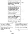
- FIG. 7 illustrates steps of a method according to an embodiment.
- a related communication scenario comprises an user equipment UE, a first access node called a serving base station, and a second access node called an assisting base station.
- the user equipment is connected to the serving base station.
- This base station may request control signaling relaying assistance from an assisting base station for the UE.
- the UE is configured to transmit and receive control signaling both via the serving base station and the assisting base station with the assisting base station relaying the control signaling from and to the serving base station, respectively. Further, the UE may monitor the radio links of all maintained connections separately.
- a further step 780 if the UE registers or detects a radio link failure for one of the links, the UE may stop transmission on that link and may transmit a radio link failure warning indication via a second maintained link, possibly relayed by the assisting base station, to the serving base station.
- the serving base station may issue the UE to reconfigure to be solely connected to the serving base station, and may issue the assisting base station to stop assistance.
- the serving base station may stop transmission and may handover the UE to the assisting base station which may become the serving base station for the UE itself.
- E-UTRAN is quickly able to combine these information, learn about UE RLF failure reasons, their statistics and can apply necessary adaptations.
- Embodiments are based on the assumption that the UE can communicate independently via two maintained connections.
- RLF radio link failure
- the UE shall trigger the standardized RLF procedure only if both links are out-of-sync. If only one of the maintained connections fails, however, a different UE behavior must be enforced as explained in the following.
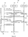
- a mobile network 800 comprises an user equipment 802, a source eNodeB 804, and an assisting eNodeB 808.
- a mobile network 900 comprises an user equipment 902, a source eNodeB 904, and an assisting eNodeB 908. Steps in Figs. 8 , 9 are labelled by integer numbers.
- RRC anchor functionality of the source and target eNodeBs 804, 904, 908 is indicated by a bold solid line and is referenced by a reference numeral 886, 986.
- RRC relay capability of the assisting eNodeB 808, 908 is indicated in Figs. 8 , 9 by a bold dashed line and is referenced by a reference numeral 888, 988.
- a measurement configuration is sent from the source eNodeB 804, 904 to the user equipment 802, 902.
- an early measurement report is sent from the UE 802, 902 to the source eNodeB 804, 904.
- the early measurement report may be issued in response to a A3 event explained with reference to Figure 2 .
- an RRC assistance request is sent from the source eNodeB 804, 904 to the assisting eNodeB 808, 908.
- an RRC assistance response including RRC reconfiguration information is sent from the assisting eNodeB 808, 908 to the source eNodeB 804, 904.
- the RRC-reconfiguration information is sent from the assisting eNodeB 808, 908 to the source eNodeB 804, 904.
- a RRC-reconfiguration is sent from the source eNodeB 804, 904 to the UE 802, 902 in a step 5.
- the source eNodeB 804, 904 starts RRC diversity.
- the assisting eNodeB 808, 908 starts RRC relaying.
- the UE 802, 902 sends a synchronization and RACH procedure request towards the assisting eNodeB 808, which accordingly sends a response to the UE 802, 902.
- the UE 802, 902 is first configured with a measurement configuration (1) issuing an early measurement report (2).
- This measurement may relate to a source cell, assisting cell or different cells.
- the source eNB 804, 904 Upon reception of this measurement report in the source eNB 804, 904 it will (if required) request an RRC diversity peering (3) with the assisting eNB 808, 908, which acknowledges this request (4) and includes the RRC-reconfiguration for the UE 802, 902 to setup RRC diversity transmission and reception, which the source eNB 804, 904 will forward to the UE 802, 902 (5).
- the source eNB 804, 904 will go into RRC diversity state where RRC messages are transmitted and received to the UE 802, 902 directly and additionally send to/received from the assisting eNB 808, 908 for relaying to/from the UE 802, 902.
- the UE 802, 902 will start a RACH procedure towards the assisting eNB 808, 908 to become synchronized to it (6).
- a RLF between the UE 802 and the assisting eNodeB 808 occurs in a step 884.
- the UE 802 stops transmitting to the assisting eNodeB 808.
- the UE 802 sends a RLF warning to the source eNodeB 804, which in turn stops in a step 8 RRC relaying to the assisting eNodeB 808.
- steps 898, 899 the source eNodeB 804 stops RRC diversity and the assisting eNodeB 808 stops RRC relaying, respectively.
- the source eNodeB 804 sends a RRC reconfiguration request to the UE 802 and the UE 802 sends a RRC reconfiguration command to the source eNodeB 804, respectively.
- the UE 802 is connected to the source eNodeB 804 in a communication up to the step 6.
- dual connectivity for the UE 802 is performed, wherein the source eNodeB 804 may represent the RRC anchor node.
- the UE 802 is connected to the source eNodeB 804, but not to the assisting eNodeB 808.
- the source eNB 804 may send a path switch request to a core network node,
- the UE 802 after the UE 802 has measured a Layer-3 RLF (i.e. timer T310 expired) towards the assisting cell ( Fig. 8 ), it will stop the transmission on this link and trigger the transmission of the (7) RLF warning message, as further described below, towards the source eNB 804.
- the source eNB 804 will send an indication to the assisting eNB 808 to stop the RRC relaying functionality (8) for the UE 802, since it is aware of the UE 802 having triggered RLF to the assisting eNB 808. This way the assisting eNB 808 is informed about the radio link failure to the UE 802 immediately, which would not have been possible with the currently standardized solution, where this state could only be estimated based on timers etc.
- RRC diversity should be deactivated in both source eNB 804 and assisting eNB 808. Only the connection between source eNB 804 and UE 802 should be maintained, thus the UE 802 is configured to stop RRC diversity, but maintain the connection to the UE 802.
- the source eNB 804 uses the RRC reconfiguration procedure (10, 11) to reconfigure the UE 802 to leave RRC diversity mode and be solely connected to the source cell.
- the system is capable of dual connectivity for the UE 802, also potential bearers terminated at the assisting eNB 808 would be reconfigured to terminate at the source eNB 804.
- the source eNB 804 also sends a path switch command towards the core network so that the packets are routed to the source eNB 804.
- Figure 8 illustrates a Radio link failure (RLF) warning for the assisting eNB 808 out-of-sync.
- RLF Radio link failure
- a reaction to a source eNB 904 out-of-sync is described.
- a RLF between the UE 902 and the source eNodeB 904 has occurred.
- the UE 902 stops transmission to the source eNodeB 904.
- a RLF warning is sent from the UE 902 to the source eNodeB 904 via the assisting eNodeB 908.
- the source eNodeB 904 sends a handover request to the assisting eNodeB 908.
- the assisting eNodeB 908 sends a handover acknowledgement to the source eNodeB 904.
- the source eNodeB 904 sends a RRC reconfiguration request via the assisting eNodeB 908 to the user equipment UE 902.
- the source eNodeB 904 stops RRC diversity and the assisting eNodeB 908 upgrades to the RRC anchor in a step 999 for the UE 902.
- the source eNodeB 904 sends a sequence number status transfer to the assisting eNodeB 908, and the UE 902 sends in a step 13 a RRC reconfiguration command to the assisting eNodeB 908.
- the assisting eNodeB 908 sends a UE context release message to the source eNodeB 904.
- the UE 902 In a communication up to the receipt of the synchronization and RACH procedure related message received by the UE 902, the UE 902 is connected to the source eNodeB 904. In a time interval between the UE 902 receiving the message in the step 6 and the message transfer in the step 13 taking place, dual connectivity for the UE 902 is performed in which the source eNodeB 904 is the RRC anchor node. From the step 13 onwards, the UE 902 is connected to the assistant eNodeB 908.
- RLF on the link to the source eNB 904 occurs and is registered within the UE 902. It will stop its transmission on this link and transmit an RLF warning indication towards the assisting eNB 908 (7) which will (since it is in RRC relaying mode) further forward this indication towards the source eNB 904.
- the source eNB 904 will than handover the UE 902 completely to the assisting eNB 908 since it can be sure the connection source 904-UE 902is lost. Therefore, it will send the handover request indication (8) to the assisting eNB 908, which is acknowledged (9) by the assisting eNB 908.
- the acknowledgment also includes the handover command for the UE 902, which the source eNB 904 is supposed to send to the UE 902.
- the source eNB 904 will send the handover command (RRC reconfiguration (11)) via the RRC relay, i.e. the assisting eNB 908, to the UE 902. Therefore, it is important that the assisting eNB 908 still remains in RRC relaying mode, even though it received and acknowledges the complete handover of the UE 902 already.
- the assisting eNB 908 can upgrade itself to be the RRC anchor for the UE 902.
- the source eNB 904 can stop RRC diversity. Both nodes 904, 908 will now follow the standardized HO procedure, i.e.
- source eNB 904 will send sequence number status transfer (12) to the assisting eNB 908 and forward buffered packets.
- the UE 902 will confirm the RRC reconfiguration to be solely connected to the assisting (now anchor) eNB 908 (13), and eventually the assisting eNB 908 will send the UE context release indication to the source eNB 904 (14).
- the assisting eNB 908 being in RRC relaying mode for the UE 902, will transmit the handover command to the UE 902 (11) itself in case the source requests a complete handover.
- the handover request acknowledge message does not need to include the handover command for the UE 902, since the source eNB 904 is not supposed to transmit it anyway.
- the source eNB 904 needs to be informed that the UE 902 is handed over to the assisting eNB 908 and that SN status transfer and buffered data transfer needs to be initiated.
- the assisting eNB 908 could also inspect the RLF warning it forwards and directly send handover acknowledgment to the source eNB 904, as well as handover command to the UE 902 itself.
- Figure 9 illustrates a radio link failure (RLF) warning for the source eNB out-of-sync.
- RLF radio link failure
- radio link failure related actions according to embodiments are described.
- the timers and constants for the UE 802, 902 to evaluate physical layer problems shall be configurable on a per link basis, thus multiple instances of the IE rlf-TimersAndConstants (or at least a subset of the corresponding timers/constants, e.g. T310, N310, N311) shall exist and be configurable in the UE 902, 902. In another embodiment, the same values are applied to the each of the links, but evaluation is still done independently.
- the UE 802, 902 evaluates separately per connected cell i if N310i consecutive "out-of-sync" indications are received from lower layers while neither in T300 i, T301 i, T304 i, T311 i and then starts timer T310 i.
- the UE Upon receiving N311 i consecutive "in-sync" indications from lower layers while T310 i is running, the UE shall stop timer T310 i.
- the separate evaluation on a per link basis shall also apply if further advanced techniques of "out-of-sync"/"in-sync" evaluations are applied, .e.g. additionally evaluating whether a measurement report was sent.
- the UE 802, 902 Upon T310 expiry of a certain cell, or maximum number of scheduling requests is reached, or RLC maximum number of retransmissions reached indication for this cell, the UE 802, 902 shall trigger the new RLF-warning procedure as defined in the following.
- the UE 802, 902 shall trigger the following modified actions and prepare the RLF-warning indication to be sent directly via a second maintained connection. Additionally the legacy RLF-Report is prepared in a modified way.
- the following two pseudo code examples may describe the method embodiments of Figures 8 , 9 with respect to a RLF procedure according to TS 36.331 V11.2.0 (2012-12), section 5.3.11.3 "Detection of RLF".
- Detection of RLF For ease of clarity, not changed pseudo code portions may have been omitted. In particular, deviations from this standard can be deduced by means of comparison with the pseudo code examples and are presented in bold for ease of visibility.
- the first pseudo code example may relate to a method embodiment in which the terminal 802, 902 may stop transmitting and receiving via the degraded or failed connection, hence may stop communicating both in an uplink direction and a downlink direction.
- the second pseudo code example may relate to method embodiment in which the terminal may continue transmitting in an uplink direction via the degraded or failed connection to the respective access node 804, 808, 904, 908 but may not receive any information via the degraded or failed connection towards the respective access node 804, 808, 904, 908.
- the terminal 802, 902 does not stop transmission/reception on the link for which T310 has expired. Expiry of T310 only means that the downlink channel has problem due to poor channel quality but this does not mean that there are any problems in uplink.
- the uplink transmissions may therefore successfully reach the base station 804, 808, 904, 908. This is expected to be beneficial especially in case the acknowledgements for the terminals uplink transmissions can be transmitted from the network to the terminal 802, 902 on an alternative link, for example a link for which RLF has not been detected.
- the terminal 802, 902 continues to transmit and receive (attempt to receive) on the link for which T310 has expired then it is possible that if the link later becomes better after RLF has been detected the terminal 802, 902 can resume use of that link.
- the terminal 802, 902 may detect a RLF on a connection to one access node 804, 808, 904, 908 of the source access node 804, 904 and the assisting access node 808, 908, the terminal 802, 902 may send, in a first option, the RLF indication to the respective other access node 804, 808, 904, 908 which may forward the RLF indication to the access node 804, 808, 904, 908 associated with the detected RLF.
- the terminal 802, 902 may stop transmission and/or reception to the access node 804, 808, 904, 908 associated with the detected RLF or may continue transmission and/or reception to the access node 804, 808, 904, 908 associated with the detected RLF.
- the terminal 802, 902 may send the RLF indication to the access node 804, 808, 904, 908 associated with the detected RLF.
- the terminal 802, 902 might not stop transmission and/or reception to this access node 804, 808, 904, 908 in this case.
- the access node 804, 808, 904, 908 may in turn forward the RLF warning to the other access node 804, 808, 904, 908 not being associated with the detected RLF.
- the terminal 802, 902 may select a set of configured links on which it sends the RLF-warning on. For example, it may send the RLF-warning to all cells or a subset of all configured links such as only on the source link.
- the terminal 802, 902 knows that it has one or more alternative links to the node 804, 808, 904, 908 offering the link for which T310 has expired, for example if there are two links from a node to a terminal 802, 902 and T310 expires only for one of these links then it would be beneficial to transmit the RLF-warning on one or more alternative links.
- the terminal 802, 902 may even send the RLF-warning on the link for which the T310 has expired.
- the benefit of sending the RLF-warning on the link for which T310 has expired is that the concerned node 804, 808, 904, 908 may need to be informed about the expiration of T310.
- the expiration of T310 indicates that the downlink quality is poor however the uplink may still have sufficiently good quality allowing the RLF-warning to reach the concerned node 804, 808, 904, 908.
- RLF-reporting may be regarded to be modified with respect to legacy RLF reporting according to TS 36.331 V11.2.0 (2012-12) which may be directed to RFL reporting for a single connection between a terminal 802, 902 and an access node 804, 808, 904, 908.
- the UE 802, 902 stores RLF related information for the (single) link where the failure occurred and sends the report to E-UTRAN upon request. The report is overridden when another RLF occurs.
- the UE 802, 902 shall trigger the original RLF procedure as well as the original RLF report only if all links fail. So, this reporting can be modified to convey information about multiple links.
- the single modified RLF report can include information about multiple or all links.
- multiple RLF reports so one per link can be created and requested independently or collectively by E-UTRA.
- CQI Channel Quality Indicator
- CQI reports received for each link in the respective network node 804, 808, 904, 908 can be forwarded to another node 804, 808, 904, 908, which is also currently connected to the UE 802, 902.
- the source eNodeB 804, 904 may be associated with a connection quality degradation
- the CQI received by the source eNodeB 804, 904 may be transmitted to the assisting eNodeB 808, 908.
- the CQI report received by the assisting eNodeB 804, 904 may be sent to the source eNodeB 804, 904.
- the network will monitor the received CQI reports received from the terminal 802, 902 regarding the terminal's different connections. If the reported CQI indicates a channel quality for one connection below a certain threshold the network will consider that connection unfit for use by the terminal 802, 902.
- the receiving eNB 804, 808, 904, 908 can utilize the information about failure reason and UE measurements etc. as given in the warning message by combining it with its own information about the working link, e.g. about current events and transmissions done to UE. So, with the RLF warning procedure, E-UTRAN is able to combine UE and eNB information to determine if the problem was related to that eNB 804, 808, 904, 908 did not receive the UE 802, 902 on the link where problems was indicated or vice versa or both.
- the eNB 804, 808, 904, 908 may experience similar faults as the UE 802, 902 e.g. maximum number of resynch attempts reached, maximum number of scheduling requests reached or maximum number of RLC retransmission reached and then eNB 804, 808, 904, 908 could ask the UE 802, 902 to provide historic data about UE events and transmissions done. This functionality can be established with another request/response message exchange triggered by the eNB 804, 808, 904, 908 and transmitted via one of the maintained connections.
- E-UTRAN is able to quickly react upon these connectivity problems and adapt its system settings to improve the performance for the UE 802, 902 and the overall system, e.g. certain key performance indicators.
- this solution will allow an operator to understand the root cause for intermittent performance degradations in a radio network and especially understand if it is a network problem or a UE problem or both.
- the method will also work in rather poor conditions since only one out of several connections to the network need to work.
- a terminal 1002 for adapting a mobile network is described.
- the terminal 1002 may correspond to the terminal 802 or 902.
- the terminal 1002 is connected to a first access node of the mobile network via a first connection and to a second access node via a second connection.
- the first access node controls a data transmission for the terminal 1002 and wherein the second access node assists in the data transmission for the terminal 1002.
- the terminal 1002 may comprise one or more interfaces 1003 to the first and second access nodes.
- the one or more interfaces 1003 may be coupled each to a processor 1005 of the terminal 1002, which processor 1005 has access to a memory 1007 of the terminal 1002.
- the terminal 1002 comprises a determination unit 1009 adapted to determining whether a quality of at least one of the first connection and the second connection is degraded, and an acquiring unit 1011 adapted to acquire quality degradation information about the degradation of the quality of at least one of the first connection and the second connection based on the determination for adapting the mobile network based on the acquired quality degradation information.
- the terminal 1002 may comprise a determination unit 1009 adapted to determining whether a quality of at least one of the first connection and the second connection may be degraded, and an acquiring unit 1011 adapted to acquire quality degradation information about the degradation of the quality of at least one of the first connection and the second connection based on the determination particularly for adapting the mobile network.
- the determination unit 1009 may be part of the processor 1005. Further, the acquiring unit 1011 may be part of the one or more interfaces 1003. The one or more interfaces 1003 may further comprise a reception unit 1013 and a sending unit 1015 for implementing receiving and sending capabilities of the one or more interfaces 1003, respectively.
- the sending unit 1015 may implement above described functionalities related to sending the quality degradation information.
- the terminal 1002 is adapted to perform a method according to embodiments described above and comprises respective functionality based units imbedded in respective physical units 1003, 1005, 1007 illustrated in Figure 10 .
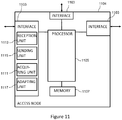
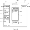
- an access node 1104 for adapting a mobile network is illustrated.
- the access node 1104 may correspond to the first access node 804, 904.
- a terminal is connected to the access node 1104 of the mobile network via a connection and to another access node via another second connection.
- the access node 1104 controls a data transmission for the terminal and the another access node assists in the data transmission for the terminal.
- the access node 1004 may comprise one or more interfaces 1103 to the terminal and the another access node.
- the one or more interfaces 1103 may be coupled each to a processor 1105 of the access node 1104, which processor 1005 has access to a memory 1107 of the access node 1104.
- the access node 1104 comprises an acquiring unit 1111 adapted to acquire quality degradation information about a degradation of a quality of at least one of the first connection and the second connection based on a determination whether the quality of at least one of the first connection and the second connection is degraded, and an adapting unit 1117 adapted to adapt the mobile network based on the acquired quality degradation information.
- the access node 1104 may comprise an acquiring unit 1111 adapted to acquire quality degradation information about a degradation of a quality of at least one of the first connection and the second connection.
- the quality degradation information may be based on a determination whether the quality of at least one of the first connection and the second connection may be degraded.
- the access node 1104 may comprise an adapting unit 1117 adapted to adapt the mobile network based on the acquired quality degradation information. In both implementations, the access node 1104 may further comprise a determination unit adapted to determine whether the quality of at least one of the connection and the another connection may be degraded.
- the acquiring unit 1111 and the adapting unit 1117 may be part of the one or more interfaces 1103.
- the one or more interfaces 1103 may further comprise a reception unit 1113 and a sending unit 1115 for implementing receiving and sending capabilities of the one or more interfaces 1103, respectively.
- the determination unit may be part of the processor 1105.
- the access node 1104 is adapted to perform a method according to embodiments described above and comprises respective functionality based units imbedded in respective physical units 1103, 1105, 1107 illustrated in Figure 11 .
- an access node 1208 for adapting a mobile network is illustrated.
- the access node 1208 may correspond to the access node 808, 908.
- a terminal is connected to the access node 1208 of the mobile network via a connection and to another access node via another connection.
- the another access node controls a data transmission for the terminal and the access node 1208 assists in the data transmission for the terminal.
- the access node 1208 may comprise one or more interfaces 1103 to the terminal and the another access node.
- the one or more interfaces 1203 may be coupled each to a processor 1205 of the access node 1208, which processor 1205 has access to a memory 1107 of the access node 1208.
- the access node 1208 comprises an adapting unit 1217 adapted to adapt the mobile network based on acquired quality degradation information about a degradation of a quality of at least one of the connection and the another connection, the acquiring of the quality degradation information being based on a determination whether a quality of at least one of the connection and the another connection is degraded.
- the access node 1208 may comprise an adapting unit 1217 adapted to adapt the mobile network based on a quality of at least one of the connection and the another connection being degraded.
- the adapting unit 1217 unit may be adapted to perform the adaption based on acquired quality degradation information about a degradation of a quality of at least one of the connection and the another connection.
- the acquiring of the quality degradation information may be based on a determination whether a quality of at least one of the connection and the another connection is degraded.
- the access node 1208 may comprise an acquiring unit 1211 adapted to acquire the quality degradation information. In both latter described implementations, the access node 1208 may also comprise a determination unit 1209 adapted to determine whether the quality of at least one of the connection and the another connection may be degraded.
- the adapting unit 1217 may be part of the one or more interfaces 1203, and the acquiring unit 1011 may be also part of the one or more interfaces 1203.
- the one or more interfaces 1203 may further comprise a reception unit 1213 and a sending unit 1215 for implementing receiving and sending capabilities of the one or more interfaces 1203, respectively.
- the determination unit 1209 may be part of the processor 1205.
- the access node 1208 is adapted to perform a method according to embodiments described above and comprises respective functionality based units imbedded in respective physical units 1203, 1205, 1207 illustrated in Figure 12 .
- the described functionality based units 1009 to 1015, 1109 to 1117, 1209 to 1217 for implementing the above described functionalities of the respective entity 1002, 1104, 1208 may be also realized in software and/or in hardware and software.
- suitable configured computer program code may be stored for implementing the above-described functionalities of the respective entity 1002, 1104 1208 in the memory 1007, 1107, 1207 of the respective above described entity 1002, 1104, 1208.
- the memory 1007, 1107, 1207 and the computer program code may form a computer program product.
- the computer program code may be also stored on a different memory loadable into the memory 1007, 1107, 1207 of the respective entity 1002, 1104, 1208.
- the computer program code may be also provided in a downloadable form, forming a further computer program product.
- an association between the physical units 1003 to 1007, 1103 to 1107, 1203 to 1207 of the terminal 1002 and access nodes 1104, 1208 illustrated in Figures 10 to 12 , respectively, and the functionality based units 1009 to 1015, 1109 to 1117, 1209 to 1217 of the terminal 1002 and access nodes 1104, 1204 illustrated these Figures, respectively, may differ from the described embodiments.
- the acquiring unit 1011 of the terminal 1002 illustrated in Figure 10 may be part of the interface 1003, the processor 1005, and the memory 1007 of the terminal 1002.
- embodiments are applicable to LTE and radio access networks of GSM and UMTS.
Landscapes
- Engineering & Computer Science (AREA)
- Computer Networks & Wireless Communication (AREA)
- Signal Processing (AREA)
- Mobile Radio Communication Systems (AREA)
Claims (27)
- Verfahren zum Anpassen eines E-UTRA-Netzes (800), wobei eine Benutzereinrichtung (802, 1002) über eine erste Verbindung mit einem ersten eNodeB (804, 1104) des E-UTRA-Netzes (800) und über eine zweite Verbindung mit einem zweiten eNodeB (808, 1208) des E-UTRA-Netzes (800) verbunden ist, wobei der erste eNodeB (804, 1104) eine Datenübertragung für die Benutzereinrichtung (802, 1002) steuert und wobei der zweite eNodeB (808, 1208) die Datenübertragung für die Benutzereinrichtung (802, 1002) unterstützt, wobei das Verfahren durch die Benutzereinrichtung (802, 1002) ausgeführt wird und Folgendes umfasst:- Bestimmen (778), ob die zweite Verbindung fehlgeschlagen ist, und- basierend auf einer Bestimmung, dass die zweite Verbindung fehlgeschlagen ist, Senden (7) einer Warnanzeige zum Funkverbindungsausfall, RLF-Warnanzeige, an den ersten eNodeB (804, 1004) über eine Funkressourcensteuerungs-Signalisierung, RRC-Signalisierung, wobei die RLF-Warnanzeige angibt, dass die zweite Verbindung fehlgeschlagen ist, wobei das Verfahren ferner Folgendes umfasst:- Empfangen einer RRC-Rekonfigurationsnachricht vom ersten eNodeB (804, 1104),- Rekonfigurieren der Benutzereinrichtung (802, 1002), um nur mit dem ersten eNodeB (804, 1104) verbunden zu werden,- als Reaktion darauf, dass die Benutzereinrichtung (802, 1002) rekonfiguriert wird, Senden einer Nachricht über die abgeschlossene RRC-Rekonfiguration an den ersten eNodeB (804, 1104) .
- Verfahren nach dem vorstehenden Anspruch, wobei das Verfahren ferner Folgendes umfasst:- Bestimmen, ob die erste Verbindung fehlgeschlagen ist.
- Verfahren nach einem der vorstehenden Ansprüche, wobei der Schritt (778) des Bestimmens, ob die erste Verbindung fehlgeschlagen ist, das Bewerten umfasst, ob die erste Verbindung fehlgeschlagen ist und/oder wobei der Schritt zum Bestimmen, ob die zweite Verbindung fehlgeschlagen ist, das Bewerten umfasst, ob die zweite Verbindung fehlgeschlagen ist.
- Verfahren nach einem der vorhergehenden Ansprüche, wobei der Schritt des Bestimmens, ob die erste Verbindung fehlgeschlagen ist, das Bewerten einer Synchronisation der Benutzereinrichtung (802, 1002) mit dem ersten eNodeB (804, 1104) in Bezug auf die Datenübertragung über die erste Verbindung umfasst und/oder der Schritt des Bestimmens, ob die zweite Verbindung fehlgeschlagen ist, das Bewerten einer Synchronisation der Benutzereinrichtung (802, 1002) mit dem zweiten eNodeB (808, 1208) in Bezug auf die Datenübertragung über die zweite Verbindung umfasst.
- Verfahren nach einem der vorstehenden Ansprüche, wobei der Schritt (778) des Bestimmens, ob die erste Verbindung fehlgeschlagen ist, die Verwendung eines ersten Zeitgebers in der Benutzereinrichtung (802, 1002) und eines ersten Zählers in der Benutzereinrichtung (802, 1002) umfasst, wobei der erste Zähler der Erfüllung einer ersten Bedingung zugeordnet ist, wobei ein Ausfall der ersten Verbindung bestimmt wird, wenn der erste Zeitgeber abläuft, wobei der erste Zeitgeber nach einer vorbestimmten Anzahl von Zählererfüllungen der ersten Bedingung gestartet wird und wobei der erste Zeitgeber nach einer vorbestimmten Anzahl von Zählererfüllungen einer anderen ersten Bedingung gestoppt wird und/oder wobei der Schritt (778) des Bestimmens, ob die zweite Verbindung fehlgeschlagen ist, die Verwendung eines zweiten Zeitgebers in der Benutzereinrichtung (802, 1002) und eines zweiten Zählers in der Benutzereinrichtung (802, 1002) umfasst, wobei der zweite Zeitgeber der Erfüllung einer zweiten Bedingung zugeordnet ist, wobei ein Ausfall der zweiten Verbindung bestimmt wird, wenn der zweite Zeitgeber abläuft, wobei der zweite Zeitgeber nach einer vorbestimmten Anzahl von Zählererfüllungen der zweiten Bedingung gestartet wird und wobei der Zeitgeber nach einer vorbestimmten Anzahl von Zählererfüllungen einer anderen zweiten Bedingung gestoppt wird.
- Verfahren nach einem der Ansprüche 2 bis 5, wobei der Schritt des Bewertens, ob die erste Verbindung fehlgeschlagen ist, das Bewerten umfasst, ob ein Maximum der erneuten Übertragung von Daten von der Benutzereinrichtung (802, 1002) über die erste Verbindung gesendet wurde und/oder wobei der Schritt des Bewertens, ob die zweite Verbindung fehlgeschlagen ist, das Bewerten umfasst, ob ein Maximum der erneuten Übertragung von Daten von der Benutzereinrichtung (802, 1002) über die zweite Verbindung gesendet wurde.
- Verfahren nach einem der Ansprüche 2 bis 6, wobei der Schritt des Bewertens, ob die erste Verbindung fehlgeschlagen ist, das Bewerten umfasst, ob ein Maximum an erfolglosen Direktzugriffsversuchen von der Benutzereinrichtung (802, 1002) über die erste Verbindung gesendet wurde, ohne eine Datenübertragung über die erste Verbindung zu empfangen, und/oder wobei der Schritt des Bewertens, ob die zweite Verbindung fehlgeschlagen ist, das Bewerten umfasst, ob ein Maximum an erfolglosen Direktzugriffsversuchen von der Benutzereinrichtung (802, 1002) über die zweite Verbindung gesendet wurde, ohne eine Datenübertragung über die zweite Verbindung zu empfangen.
- Verfahren nach einem der vorstehenden Ansprüche, wobei mindestens eine aus der folgenden Gruppe ausgewählte Information an den ersten eNodeB (804) gesendet wird:- eine Zellenidentifikationsangabe, die eine Identifizierung eines Bereichs, insbesondere einer Zelle, angibt, der vom zweiten eNodeB (808, 1208) bedient wird, der der fehlgeschlagenen Verbindung zugeordnet ist, insbesondere eine PCell-Identifikation (ID), eine globale Zellen-ID, eine physische Zellen-ID oder eine Trägerfrequenz der Zelle,- Informationen über Messergebnisse, die für den vom zweiten, der fehlgeschlagenen Verbindung zugeordneten eNodeB (808, 1208) bedienten Bereich erhalten wurden, und für einen früheren Zeitraum erhalten wurden,- Informationen über ein Messergebnis, das für einen Bereich, insbesondere eine Zelle, erhalten wurde, der vom ersten eNodeB (804, 1104), welcher der nicht fehlgeschlagenen Verbindung zugeordnet ist, bedient wird, und für einen früheren Zeitraum erhalten wurde,- Informationen über ein Messergebnis, das für mindestens einen weiteren Bereich, insbesondere eine weitere Zelle, erhalten wurde, der von einem weiteren eNodeB bedient wird, der sich vom ersten eNodeB (804, 1104) und zweiten eNodeB (808, 1208) unterscheidet, und welches für einen früheren Zeitraum erhalten wurde, insbesondere eine Kennung für die Messung,- eine Verbindungsangabe, die auf die fehlgeschlagene Verbindung hinweist, und- eine Fehlerursache.
- Verfahren nach Anspruch 8, wobei die RLF-Warnanzeige und die mindestens eine Information zusammen in einer Nachricht gesendet werden.
- Verfahren nach einem der vorstehenden Ansprüche, wobei die RLC-Warnanzeige in einer Verbindungsausfall-Information enthalten ist und/oder wobei die mindestens eine Information in der Verbindungsausfall-Information enthalten ist.
- Verfahren nach einem der vorstehenden Ansprüche, wobei der Schritt des Empfangens der RRC-Rekonfigurationsnachricht vom ersten eNodeB (804, 1104), nach dem Schritt des Sendens der RLF-Warnanzeige durchgeführt wird, und wobei der Schritt des Rekonfigurierens der Benutzereinrichtung (802, 1002), um nur mit dem ersten eNodeB (804, 1104) verbunden zu werden, in Reaktion auf das Empfangen der RRC-Rekonfigurationsnachricht durchgeführt wird.
- Verfahren nach einem der vorstehenden Ansprüche, wobei das Verfahren ferner Folgendes umfasst:- Bestimmen (778), ob die erste Verbindung und die zweite Verbindung fehlgeschlagen sind,- basierend auf einer Bestimmung, dass die erste Verbindung und die zweite Verbindung fehlgeschlagen sind, Einleiten eines RLF-Verfahrens.
- Verfahren nach Anspruch 12, wobei das RLF-Verfahren einem standardisierten RLF-Verfahren in der Technischen Spezifikation 36.331 Version 11.2.0 (2012-12) für nur eine Verbindung zwischen der Benutzereinrichtung (802, 1002) und dem E-UTRA-Netz (800) entspricht.
- Verfahren nach einem der Ansprüche 12 oder 13, wobei das Verfahren ferner Folgendes umfasst:- Senden eines oder mehrerer Verbindungsausfallberichte durch die Benutzereinrichtung (802, 1002) an einen weiteren eNodeB des E-UTRA-Netzes (800), wobei der eine oder die mehreren Verbindungsausfallberichte Informationen über die erste und/oder zweite Verbindung umfassen.
- Verfahren nach einem der vorstehenden Ansprüche, wobei die Benutzereinrichtung (802, 1002) gemäß einer dualen Konnektivität arbeitet, bei der die Benutzereinrichtung (802, 1002) eine Datenübertragung über die erste Verbindung und die zweite Verbindung gleichzeitig sendet und empfängt.
- Verfahren zum Anpassen eines E-UTRA-Netzes (800), wobei eine Benutzereinrichtung (802, 1002) über eine erste Verbindung mit einem ersten eNodeB (804, 1104) des E-UTRA-Netzes (800) und über eine zweite Verbindung mit einem zweiten eNodeB (808, 1208) des E-UTRA-Netzes (800) verbunden ist, wobei der erste eNodeB (804, 1104) eine Datenübertragung für die Benutzereinrichtung (802, 1002) steuert und wobei der zweite eNodeB (808, 1208) die Datenübertragung für die Benutzereinrichtung (802, 1002) unterstützt, wobei das Verfahren durch den ersten eNodeB (804, 1104) ausgeführt wird und Folgendes umfasst:- Empfangen (7) einer Warnanzeige zum Funkverbindungsausfall, RLF-Warnanzeige, von der Benutzereinrichtung (802, 1002) über eine Funkressourcensteuerungs-Signalisierung, RRC-Signalisierung, wobei die RLF-Warnanzeige angibt, dass die zweite Verbindung fehlgeschlagen ist,- basierend auf der empfangenen RLF-Warnanzeige, Senden (10) einer RRC-Rekonfigurationsnachricht an die Benutzereinrichtung (802, 1002) zum Rekonfigurieren der Benutzereinrichtung (802, 1002), um nur mit dem ersten eNodeB (804, 1104) verbunden zu werden, und- Empfangen (11) einer Nachricht über die abgeschlossene RRC-Rekonfiguration von der Benutzereinrichtung (802, 1002).
- Verfahren nach Anspruch 16, ferner umfassend:- Auffordern (8), ausgehend vom zweiten eNodeB (808, 1208), die zweite Verbindung zu trennen, und- Stoppen (898), um den zweiten eNodeB (808, 1208) für die Datenübertragung für die Benutzereinrichtung (802, 1002) zu verwenden.
- Verfahren nach Anspruch 17, wobei der Schritt (898) des Stoppens zur Verwendung des zweiten eNodeB (808, 1208) das Rekonfigurieren eines oder mehrerer Träger umfasst, die am zweiten eNodeB (808, 1208) enden, um am ersten eNodeB (804, 1104) zu enden.
- Verfahren nach einem der Ansprüche 16 bis 18, wobei das Verfahren ferner Folgendes umfasst:- Senden eines Pfadumschaltbefehls an ein Kernnetz, um anzugeben, dass Datenpakete über den ersten eNodeB (804, 1104) geroutet werden sollen.
- Verfahren nach einem der Ansprüche 16 bis 19, wobei der erste eNodeB (804, 1104) gemäß doppelter Konnektivität arbeitet, wobei der erste eNodeB (804, 1104) eine Backhaul-Verbindung zum zweiten eNodeB (808, 1208) aufweist, um eine Datenübertragung an die Benutzereinrichtung (802, 1002) über den zweiten eNodeB (808, 1208) zu senden.
- Benutzereinrichtung (802, 1002) zum Anpassen eines E-UTRA-Netzes (800), wobei die Benutzereinrichtung (802, 1002) über eine erste Verbindung mit einem ersten eNodeB (804, 1104) des E-UTRA-Netzes (800) und über eine zweite Verbindung mit einem zweiten eNodeB (808, 1208) des E-UTRA-Netzes (800) verbunden ist, wobei der erste eNodeB (804, 1104) eine Datenübertragung für die Benutzereinrichtung (802, 1002) steuert und wobei der zweite eNodeB (808, 1208) die Datenübertragung für die Benutzereinrichtung (802, 1002) unterstützt, wobei die Benutzereinrichtung (802, 1002) angepasst ist zum- Bestimmen, ob die zweite Verbindung fehlgeschlagen ist, und- basierend auf einer Bestimmung, dass die zweite Verbindung fehlgeschlagen ist, Senden einer Warnanzeige zum Funkverbindungsausfall, RLF-Warnanzeige, an den ersten eNodeB (804, 1004) über eine Funkressourcensteuerungs-Signalisierung, RRC-Signalisierung, wobei die RLF-Warnanzeige angibt, dass die zweite Verbindung fehlgeschlagen ist, wobei die Benutzereinrichtung (802, 1002) ferner angepasst ist zum:- Empfangen einer RRC-Rekonfigurationsnachricht vom ersten eNodeB (804, 1104),- Rekonfigurieren der Benutzereinrichtung (802, 1002), um nur mit dem ersten eNodeB (804, 1104) verbunden zu werden,- als Reaktion darauf, dass die Benutzereinrichtung (802, 1002) rekonfiguriert wird, Senden einer Nachricht über die abgeschlossene RRC-Rekonfiguration an den ersten eNodeB (804, 1104) .
- Benutzereinrichtung (802, 1002) nach Anspruch 21, wobei die Benutzereinrichtung (802, 1002) angepasst ist, um ein Verfahren nach einem der Ansprüche 2 bis 15 auszuführen.
- Erster eNodeB (804, 1104) zum Anpassen eines E-UTRA-Netzes (800), wobei eine Benutzereinrichtung (802, 1002) über eine erste Verbindung mit dem ersten eNodeB (804, 1104) des E-UTRA-Netzes (800) und über eine zweite Verbindung mit einem zweiten eNodeB (808, 1208) des E-UTRA-Netzes (800) verbunden ist, wobei der erste eNodeB (804, 1104) eine Datenübertragung für die Benutzereinrichtung (802, 1002) steuert und wobei der zweite eNodeB (808, 1208) die Datenübertragung für die Benutzereinrichtung (802, 1002) unterstützt, wobei der erste eNodeB (804, 1104) angepasst ist zum:- Empfangen einer Warnanzeige zum Funkverbindungsausfall, RLF-Warnanzeige, von der Benutzereinrichtung (802, 1002) über eine Funkressourcensteuerungs-Signalisierung, RRC-Signalisierung, wobei die RLF-Warnanzeige angibt, dass die zweite Verbindung fehlgeschlagen ist,- basierend auf der empfangenen RLF-Warnanzeige, Senden einer RRC-Rekonfigurationsnachricht an die Benutzereinrichtung (802, 1002) zum Rekonfigurieren der Benutzereinrichtung (802, 1002), um nur mit dem ersten eNodeB (804, 1104) verbunden zu werden, und- Empfangen einer Nachricht über die abgeschlossene RRC-Rekonfiguration von der Benutzereinrichtung (802, 1002).
- Erster eNodeB (804, 1104) nach Anspruch 23, wobei der erste eNodeB (804, 1104) angepasst ist, um ein Verfahren nach einem der Ansprüche 17 bis 20 auszuführen.
- E-UTRA-Netz (800), umfassend eine Benutzereinrichtung (802, 1002) nach Anspruch 21 oder 22 und einen ersten eNodeB (804, 1104) nach Anspruch 23 oder 24.
- Computerprogramm, das, wenn es von einem Prozessor ausgeführt wird, angepasst ist, um ein Verfahren zum Anpassen eines E-UTRA-Netzes (800) nach einem der Ansprüche 1 bis 20 auszuführen oder zu steuern.
- Computerprogrammprodukt, umfassend Programmcode, der von mindestens einem Prozessor auszuführen ist, wodurch der mindestens eine Prozessor veranlasst wird, ein Verfahren nach einem der Ansprüche 1 bis 20 auszuführen.
Priority Applications (5)
| Application Number | Priority Date | Filing Date | Title |
|---|---|---|---|
| PL19161302T PL3515118T3 (pl) | 2013-01-18 | 2014-01-17 | Dostosowywanie sieci mobilnej |
| DK19161302.5T DK3515118T3 (da) | 2013-01-18 | 2014-01-17 | Tilpasning af et mobilnetværk |
| EP21191821.4A EP3975617A1 (de) | 2013-01-18 | 2014-01-17 | Anpassung eines mobilfunknetzes |
| EP19161302.5A EP3515118B1 (de) | 2013-01-18 | 2014-01-17 | Anpassung eines mobilfunknetzes |
| PL16204093T PL3217719T3 (pl) | 2013-01-18 | 2014-01-17 | Dostosowywanie sieci mobilnej |
Applications Claiming Priority (3)
| Application Number | Priority Date | Filing Date | Title |
|---|---|---|---|
| US201361754322P | 2013-01-18 | 2013-01-18 | |
| PCT/EP2014/050868 WO2014111499A1 (en) | 2013-01-18 | 2014-01-17 | Adapting a mobile network |
| EP14700715.7A EP2946596B1 (de) | 2013-01-18 | 2014-01-17 | Anpassung eines mobilfunknetzes |
Related Parent Applications (2)
| Application Number | Title | Priority Date | Filing Date |
|---|---|---|---|
| EP14700715.7A Division-Into EP2946596B1 (de) | 2013-01-18 | 2014-01-17 | Anpassung eines mobilfunknetzes |
| EP14700715.7A Division EP2946596B1 (de) | 2013-01-18 | 2014-01-17 | Anpassung eines mobilfunknetzes |
Related Child Applications (2)
| Application Number | Title | Priority Date | Filing Date |
|---|---|---|---|
| EP19161302.5A Division EP3515118B1 (de) | 2013-01-18 | 2014-01-17 | Anpassung eines mobilfunknetzes |
| EP21191821.4A Division EP3975617A1 (de) | 2013-01-18 | 2014-01-17 | Anpassung eines mobilfunknetzes |
Publications (2)
| Publication Number | Publication Date |
|---|---|
| EP3217719A1 EP3217719A1 (de) | 2017-09-13 |
| EP3217719B1 true EP3217719B1 (de) | 2019-04-03 |
Family
ID=49989775
Family Applications (4)
| Application Number | Title | Priority Date | Filing Date |
|---|---|---|---|
| EP14700715.7A Active EP2946596B1 (de) | 2013-01-18 | 2014-01-17 | Anpassung eines mobilfunknetzes |
| EP16204093.5A Active EP3217719B1 (de) | 2013-01-18 | 2014-01-17 | Anpassung eines mobilfunknetzes |
| EP21191821.4A Pending EP3975617A1 (de) | 2013-01-18 | 2014-01-17 | Anpassung eines mobilfunknetzes |
| EP19161302.5A Active EP3515118B1 (de) | 2013-01-18 | 2014-01-17 | Anpassung eines mobilfunknetzes |
Family Applications Before (1)
| Application Number | Title | Priority Date | Filing Date |
|---|---|---|---|
| EP14700715.7A Active EP2946596B1 (de) | 2013-01-18 | 2014-01-17 | Anpassung eines mobilfunknetzes |
Family Applications After (2)
| Application Number | Title | Priority Date | Filing Date |
|---|---|---|---|
| EP21191821.4A Pending EP3975617A1 (de) | 2013-01-18 | 2014-01-17 | Anpassung eines mobilfunknetzes |
| EP19161302.5A Active EP3515118B1 (de) | 2013-01-18 | 2014-01-17 | Anpassung eines mobilfunknetzes |
Country Status (23)
| Country | Link |
|---|---|
| US (3) | US10631222B2 (de) |
| EP (4) | EP2946596B1 (de) |
| JP (1) | JP6029774B2 (de) |
| KR (1) | KR101689986B1 (de) |
| CN (2) | CN111586775A (de) |
| AU (1) | AU2014206876B2 (de) |
| BR (1) | BR112015017180B1 (de) |
| CA (1) | CA2898564C (de) |
| CL (1) | CL2015002021A1 (de) |
| DK (3) | DK2946596T3 (de) |
| ES (3) | ES2733578T3 (de) |
| HK (1) | HK1219198A1 (de) |
| HU (1) | HUE044533T2 (de) |
| IL (1) | IL239842B (de) |
| MA (1) | MA38263B1 (de) |
| MX (1) | MX348985B (de) |
| MY (1) | MY177868A (de) |
| NZ (1) | NZ710169A (de) |
| PL (3) | PL2946596T3 (de) |
| PT (1) | PT2946596T (de) |
| RU (1) | RU2618509C2 (de) |
| TR (1) | TR201906324T4 (de) |
| WO (1) | WO2014111499A1 (de) |
Families Citing this family (63)
| Publication number | Priority date | Publication date | Assignee | Title |
|---|---|---|---|---|
| JP6167471B2 (ja) * | 2012-03-08 | 2017-07-26 | ヤマハ株式会社 | 無線端末装置 |
| WO2013141147A1 (ja) * | 2012-03-19 | 2013-09-26 | 京セラ株式会社 | 移動通信システム及び移動通信方法 |
| JP5823939B2 (ja) * | 2012-09-13 | 2015-11-25 | 株式会社Nttドコモ | 移動通信システム、無線基地局及び移動局 |
| EP2946596B1 (de) * | 2013-01-18 | 2017-03-15 | Telefonaktiebolaget LM Ericsson (publ) | Anpassung eines mobilfunknetzes |
| US9930581B2 (en) * | 2013-01-22 | 2018-03-27 | Avago Technologies General Ip (Singapore) Pte. Ltd. | Addressing communication failure in multiple connection systems |
| JP6443326B2 (ja) | 2013-02-28 | 2018-12-26 | 日本電気株式会社 | 無線通信システム、無線局、通信制御方法、及びプログラム |
| KR20140120806A (ko) * | 2013-04-04 | 2014-10-14 | 주식회사 케이티 | Small cell에서 RLF(Radio Link Failure)를 detection 하는 방법 및 장치 |
| GB2512659A (en) * | 2013-04-05 | 2014-10-08 | Nec Corp | Communication system |
| JP5956065B2 (ja) * | 2013-04-05 | 2016-07-20 | 京セラ株式会社 | 基地局、ユーザ端末、及びプロセッサ |
| CN104247504B (zh) | 2013-04-16 | 2018-05-11 | 华为技术有限公司 | 小区切换方法及设备 |
| CN104349361B (zh) * | 2013-08-06 | 2019-05-17 | 上海诺基亚贝尔股份有限公司 | 用于无线资源控制连接的方法及装置 |
| WO2015033015A1 (en) * | 2013-09-09 | 2015-03-12 | Nokia Corporation | Detection and recovery from loss of small cell connection |
| US9942820B2 (en) * | 2013-12-02 | 2018-04-10 | Apple Inc. | Systems and methods for cross-cell carrier aggregation for coverage balance improvement |
| CN104753627A (zh) * | 2013-12-26 | 2015-07-01 | 中兴通讯股份有限公司 | 多路径传输方法、系统及数据发送装置和数据接收装置 |
| US10306695B2 (en) | 2014-01-31 | 2019-05-28 | Qualcomm Incorporated | Procedures for managing secondary eNB (SeNB) radio link failure (S-RLF) in dual connectivity scenarios |
| US10979945B2 (en) * | 2014-03-25 | 2021-04-13 | Sony Corporation | Device to reduce consumption of radio resources of a macrocell |
| US20150334767A1 (en) * | 2014-05-13 | 2015-11-19 | Htc Corporation | Device of Handling Measurement Configuration |
| US20170251407A1 (en) * | 2014-08-18 | 2017-08-31 | Nokia Solutions And Networks Oy | Method and apparatus for sending handover indication to assisting cell |
| US11089648B2 (en) * | 2015-01-30 | 2021-08-10 | Kyocera Corporation | User terminal for executing dual connectivity |
| WO2016127311A1 (zh) * | 2015-02-10 | 2016-08-18 | 华为技术有限公司 | 终端建立连接的方法、第二节点、第一终端和第二终端 |
| MY194317A (en) | 2015-02-13 | 2022-11-28 | Ericsson Telefon Ab L M | Multi-path transmission control protocol connections |
| CN107637115B (zh) * | 2015-03-19 | 2021-09-14 | 诺基亚通信公司 | 验证移动无线电通信网络的操作的方法 |
| US9894702B2 (en) * | 2015-05-14 | 2018-02-13 | Intel IP Corporation | Performing primary cell functions in a secondary cell |
| US10200177B2 (en) | 2015-06-12 | 2019-02-05 | Comcast Cable Communications, Llc | Scheduling request on a secondary cell of a wireless device |
| US9894681B2 (en) | 2015-06-12 | 2018-02-13 | Ofinno Technologies, Llc | Uplink scheduling in a wireless device and wireless network |
| US9948487B2 (en) | 2015-06-15 | 2018-04-17 | Ofinno Technologies, Llc | Uplink resource allocation in a wireless network |
| US9723543B2 (en) * | 2015-07-08 | 2017-08-01 | Blackberry Limited | Systems and methods for managing a UE-to-network relay |
| US11700555B2 (en) * | 2015-08-14 | 2023-07-11 | Qualcomm Incorporated | Mobility design for eMTC |
| KR102564318B1 (ko) * | 2015-08-21 | 2023-08-07 | 삼성전자주식회사 | 무선 통신 시스템에서 다중 연결을 이용한 핸드오버를 지원하는 장치 및 방법 |
| PL3691397T3 (pl) | 2015-10-05 | 2022-08-08 | Telefonaktiebolaget Lm Ericsson (Publ) | Sposoby i układy w sieci komunikacji bezprzewodowej dla zarządzania problemem z łączem radiowym pomiędzy urządzeniem bezprzewodowym a obsługującym węzłem sieciowym |
| KR102460350B1 (ko) * | 2015-11-06 | 2022-10-28 | 삼성전자주식회사 | 통신 시스템에서 데이터 송수신 방법 및 장치 |
| CN107171820B (zh) * | 2016-03-08 | 2019-12-31 | 北京京东尚科信息技术有限公司 | 信息传输、发送、获取方法和装置 |
| US10959138B2 (en) * | 2016-03-30 | 2021-03-23 | Sharp Kabushiki Kaisha | Terminal apparatus, base station apparatus, communication method, and control method |
| CN113423123B (zh) | 2016-04-01 | 2022-08-23 | 北京三星通信技术研究有限公司 | 一种支持无缝切换的方法及基站设备 |
| US10021617B2 (en) * | 2016-04-01 | 2018-07-10 | Lg Electronics Inc. | Method and apparatus for performing, by terminal in WLAN interworking operation, handover |
| EP3497800A1 (de) * | 2016-08-11 | 2019-06-19 | Sony Corporation | Basisstation, benutzergerät und verfahren für mobiltelekommunikationssystem |
| JP6920417B2 (ja) * | 2016-08-12 | 2021-08-18 | テレフオンアクチーボラゲット エルエム エリクソン(パブル) | 動的リンク選択 |
| JP6838142B2 (ja) * | 2016-09-22 | 2021-03-03 | オッポ広東移動通信有限公司Guangdong Oppo Mobile Telecommunications Corp., Ltd. | リンク管理のための方法及び装置 |
| CN106797648B (zh) * | 2016-11-04 | 2020-12-18 | 北京小米移动软件有限公司 | Rrc消息的发送方法及装置 |
| US10405231B2 (en) * | 2017-04-24 | 2019-09-03 | Motorola Mobility Llc | Switching between packet duplication operating modes |
| CN109245870B (zh) * | 2017-06-16 | 2021-12-28 | 华为技术有限公司 | 处理无线链路失败方法、终端设备和基站 |
| EP3664501A4 (de) * | 2017-08-11 | 2020-07-15 | Huawei Technologies Co., Ltd. | Messverfahren, vorrichtung und system |
| CN110771244A (zh) * | 2017-08-11 | 2020-02-07 | Oppo广东移动通信有限公司 | 一种控制方法、节点及计算机存储介质 |
| US10757615B2 (en) | 2017-09-13 | 2020-08-25 | Comcast Cable Communications, Llc | Radio link failure information for PDCP duplication |
| US20190150014A1 (en) * | 2017-11-16 | 2019-05-16 | Nokia Technologies Oy | Early measurement reporting for cell access |
| CN110099417B (zh) | 2018-01-30 | 2021-07-23 | 中国移动通信有限公司研究院 | 切换方法、信息交互方法、设备及计算机可读存储介质 |
| CN111713135B (zh) * | 2018-02-14 | 2023-02-17 | 上海诺基亚贝尔股份有限公司 | 用于切换期间的优先化随机接入的方法和装置 |
| CN113286318B (zh) * | 2018-03-16 | 2023-12-22 | 维沃移动通信有限公司 | 测量方法、测量配置方法、终端及网络设备 |
| CN110351790A (zh) * | 2018-04-04 | 2019-10-18 | 惠州Tcl移动通信有限公司 | 基于双连接的通信切换方法及装置 |
| US11470517B2 (en) | 2018-06-12 | 2022-10-11 | Nokia Technologies Oy | Two-step addition of a primary-secondary cell, PSCell, in a multi-connected handover |
| CN110830527A (zh) * | 2018-08-07 | 2020-02-21 | 阿里巴巴集团控股有限公司 | 一种网络间数据通信的方法、装置及数据通信系统 |
| CN113170520A (zh) * | 2018-10-10 | 2021-07-23 | 瑞典爱立信有限公司 | 在传输可靠性中使用的方法和设备 |
| CN111132203B (zh) * | 2018-10-31 | 2021-11-16 | 维沃移动通信有限公司 | 一种处理方法及终端 |
| US11006342B2 (en) * | 2018-11-12 | 2021-05-11 | Qualcomm Incorporated | Handover techniques in wireless communications |
| US10667192B1 (en) | 2018-11-12 | 2020-05-26 | Qualcomm Incorporated | Handover techniques in wireless communications |
| US20220279395A1 (en) * | 2019-06-28 | 2022-09-01 | Nokia Technologies Oy | Early data transmission for dual connectivity or carrier aggregation |
| CN112218344B (zh) * | 2019-07-12 | 2022-12-30 | 华为技术有限公司 | 一种通信方法及装置 |
| CN112399497A (zh) * | 2019-08-15 | 2021-02-23 | 华为技术有限公司 | 通信方法和通信装置 |
| US20220295406A1 (en) * | 2020-03-23 | 2022-09-15 | Sharp Kabushiki Kaisha | Base station, terminal, communication system, and control method |
| US11277318B2 (en) * | 2020-04-30 | 2022-03-15 | Accenture Global Solutions Limited | Analyzing a communication network device, based on capacity analyses associated with decommissioning the communication network device, to determine next actions |
| EP4140246A1 (de) * | 2020-05-28 | 2023-03-01 | Google LLC | Anpassung von funkzugangsnetzwerkverbindungen auf basis von kommunikationsfehlern |
| US11438273B2 (en) * | 2020-07-20 | 2022-09-06 | Altiostar Networks, Inc. | Real-time processing in wireless communications systems |
| CN116887338B (zh) * | 2023-09-06 | 2023-12-08 | 南京欣网通信科技股份有限公司 | 基于大数据的5g移动网络实时调整方法 |
Family Cites Families (34)
| Publication number | Priority date | Publication date | Assignee | Title |
|---|---|---|---|---|
| ATE341903T1 (de) * | 1997-03-12 | 2006-10-15 | Alcatel Network Syst | Verfahren und system zur verteilter wiederherstellung eines fernmeldenetzes |
| US6728216B1 (en) * | 1998-02-27 | 2004-04-27 | Advanced Micro Devices, Inc. | Arrangement in a network repeater for monitoring link integrity and selectively down shifting link speed based on local configuration signals |
| US6662019B2 (en) * | 2000-12-21 | 2003-12-09 | Lucent Technologies Inc. | Power control and transmission rate parameters of a secondary channel in a wireless communication system |
| WO2003084156A1 (fr) * | 2002-03-29 | 2003-10-09 | Ntt Docomo, Inc. | Procede d'administration de communication dans une communication de type connexion, dispositif de relais associe et dispositif de gestion de comptabilite |
| US8218511B2 (en) * | 2003-08-19 | 2012-07-10 | Ntt Docomo, Inc. | Accurate control of transmission information ad hoc networks |
| CN100370880C (zh) * | 2004-11-22 | 2008-02-20 | 华为技术有限公司 | 一种在切换后保持睡眠状态的方法 |
| US7899495B2 (en) | 2006-07-14 | 2011-03-01 | Qualcomm Incorporated | Methods and apparatus for supporting multiple connections |
| US8923321B2 (en) * | 2006-07-28 | 2014-12-30 | Motorola Mobility Llc | Apparatus and method for handling control channel reception/decoding failure in a wireless VoIP communication system |
| CA2681004A1 (en) | 2007-03-13 | 2008-09-18 | Interdigital Technology Corporation | Cell reselection process for wireless communications |
| KR20140082862A (ko) | 2007-04-23 | 2014-07-02 | 인터디지탈 테크날러지 코포레이션 | 무선 링크 및 핸드오버 실패 처리 |
| EP2145493B1 (de) * | 2007-06-19 | 2015-08-12 | LG Electronics Inc. | Erweiterung der lte-zufallzugriffsprozedur |
| US8391906B2 (en) * | 2007-11-16 | 2013-03-05 | Qualcomm Incorporated | Basing neighbor list updates on a radio link failure |
| KR101435835B1 (ko) * | 2008-03-31 | 2014-08-29 | 엘지전자 주식회사 | 단말기 및 이것의 채널 버퍼링 방법 |
| US20100080116A1 (en) * | 2008-09-29 | 2010-04-01 | Qualcomm Incorporated | Re-establishing a radio resource control connection with a non-prepared base station |
| US9271204B2 (en) | 2008-11-17 | 2016-02-23 | Qualcomm Incorporated | Mobility management based on radio link failure reporting |
| CN101815314A (zh) * | 2009-02-20 | 2010-08-25 | 华为技术有限公司 | 发现无线网络问题的方法、装置及系统 |
| CN104917598B (zh) | 2009-03-16 | 2018-12-11 | Lg电子株式会社 | 支持载波聚合的方法和设备 |
| WO2010110594A2 (ko) * | 2009-03-25 | 2010-09-30 | (주)엘지전자 | 이동통신 시스템에서 핸드오버 방법 및 장치 |
| US8553547B2 (en) * | 2009-03-30 | 2013-10-08 | Broadcom Corporation | Systems and methods for retransmitting packets over a network of communication channels |
| US8768362B2 (en) | 2009-06-22 | 2014-07-01 | Sharp Kabushiki Kaisha | Communication system, mobile station, base station, and communication method |
| CN101959262B (zh) | 2009-07-15 | 2015-07-22 | 中兴通讯股份有限公司 | 切换失败指示信息的通知方法与装置 |
| US20110170422A1 (en) * | 2010-01-08 | 2011-07-14 | Rose Qingyang Hu | System and method for coordinated multi-point network operation to reduce radio link failure |
| JP4970559B2 (ja) * | 2010-01-21 | 2012-07-11 | 株式会社エヌ・ティ・ティ・ドコモ | 移動通信システム、ネットワーク装置及び移動通信方法 |
| JP2011166372A (ja) | 2010-02-08 | 2011-08-25 | Ntt Docomo Inc | 移動通信方法及び無線基地局 |
| CN102754496A (zh) * | 2010-02-12 | 2012-10-24 | 交互数字专利控股公司 | 用于增强小区边缘用户性能和通过下行链路协作分量载波信号发送无线电链路失败情况的方法和设备 |
| JP5447103B2 (ja) * | 2010-03-31 | 2014-03-19 | 富士通株式会社 | 無線接続のための方法、装置及びシステム |
| US20120002174A1 (en) * | 2010-06-30 | 2012-01-05 | Shin-Gwo Shiue | Light source system of pico projector |
| US9307434B2 (en) | 2011-02-17 | 2016-04-05 | Telefonaktiebolaget L M Ericsson (Publ) | Methods and devices for reporting inter-radio access technology measurements |
| EP2695341A1 (de) | 2011-04-01 | 2014-02-12 | Intel Corporation | Verfahren, vorrichtungen und systeme für flexible reihungsanpassung in einem drahtlosen kommunikationsnetz |
| US9119122B2 (en) * | 2011-04-12 | 2015-08-25 | Telefonaktiebolaget L M Ericsson (Publ) | Apparatus, method, and computer program product for adjusting handover parameters |
| EP2777326B1 (de) | 2011-11-10 | 2020-01-08 | Telefonaktiebolaget LM Ericsson (publ) | Verfahren und anordnung zur handhabung einer datenübertragung in einem mobiltelefonnetzwerk |
| CN102685855B (zh) * | 2012-05-14 | 2014-11-19 | 中国联合网络通信集团有限公司 | 小区驻留方法和用户设备 |
| US20140120930A1 (en) * | 2012-10-31 | 2014-05-01 | Nokia Siemens Networks Oy | Method, Apparatus, Computer Program Product and System for Communicating Predictions |
| EP2946596B1 (de) * | 2013-01-18 | 2017-03-15 | Telefonaktiebolaget LM Ericsson (publ) | Anpassung eines mobilfunknetzes |
-
2014
- 2014-01-17 EP EP14700715.7A patent/EP2946596B1/de active Active
- 2014-01-17 PL PL14700715T patent/PL2946596T3/pl unknown
- 2014-01-17 WO PCT/EP2014/050868 patent/WO2014111499A1/en active Application Filing
- 2014-01-17 KR KR1020157022265A patent/KR101689986B1/ko active IP Right Grant
- 2014-01-17 PL PL19161302T patent/PL3515118T3/pl unknown
- 2014-01-17 MY MYPI2015702288A patent/MY177868A/en unknown
- 2014-01-17 RU RU2015134536A patent/RU2618509C2/ru active
- 2014-01-17 AU AU2014206876A patent/AU2014206876B2/en active Active
- 2014-01-17 JP JP2015553086A patent/JP6029774B2/ja active Active
- 2014-01-17 EP EP16204093.5A patent/EP3217719B1/de active Active
- 2014-01-17 HU HUE16204093 patent/HUE044533T2/hu unknown
- 2014-01-17 US US14/761,770 patent/US10631222B2/en active Active
- 2014-01-17 DK DK14700715.7T patent/DK2946596T3/en active
- 2014-01-17 DK DK16204093.5T patent/DK3217719T3/da active
- 2014-01-17 EP EP21191821.4A patent/EP3975617A1/de active Pending
- 2014-01-17 DK DK19161302.5T patent/DK3515118T3/da active
- 2014-01-17 ES ES16204093T patent/ES2733578T3/es active Active
- 2014-01-17 NZ NZ710169A patent/NZ710169A/en unknown
- 2014-01-17 BR BR112015017180-0A patent/BR112015017180B1/pt active IP Right Grant
- 2014-01-17 PT PT147007157T patent/PT2946596T/pt unknown
- 2014-01-17 CN CN201911377569.9A patent/CN111586775A/zh active Pending
- 2014-01-17 PL PL16204093T patent/PL3217719T3/pl unknown
- 2014-01-17 EP EP19161302.5A patent/EP3515118B1/de active Active
- 2014-01-17 CN CN201480016854.7A patent/CN105191402B/zh active Active
- 2014-01-17 ES ES19161302T patent/ES2895156T3/es active Active
- 2014-01-17 CA CA2898564A patent/CA2898564C/en active Active
- 2014-01-17 MX MX2015009235A patent/MX348985B/es active IP Right Grant
- 2014-01-17 TR TR2019/06324T patent/TR201906324T4/tr unknown
- 2014-01-17 ES ES14700715.7T patent/ES2628296T3/es active Active
-
2015
- 2015-07-08 IL IL239842A patent/IL239842B/en active IP Right Grant
- 2015-07-10 MA MA38263A patent/MA38263B1/fr unknown
- 2015-07-20 CL CL2015002021A patent/CL2015002021A1/es unknown
-
2016
- 2016-06-21 HK HK16107093.3A patent/HK1219198A1/zh unknown
-
2020
- 2020-03-11 US US16/815,577 patent/US10959151B2/en active Active
-
2021
- 2021-02-08 US US17/170,078 patent/US11570681B2/en active Active
Non-Patent Citations (1)
| Title |
|---|
| None * |
Also Published As
Similar Documents
| Publication | Publication Date | Title |
|---|---|---|
| US11570681B2 (en) | Adapting a mobile network | |
| US9544822B2 (en) | Handover signaling assistance | |
| US11070996B2 (en) | Method for controlling wireless link and wireless connection of terminal in wireless communication system, and apparatus supporting same | |
| US8903399B2 (en) | Methods and network nodes for detecting short stay handover | |
| US20140050197A1 (en) | Method for Providing Information in a Cellular Wireless Communication System | |
| US20230086398A1 (en) | Master cell group (mcg) failure and radio link failure (rlf) reporting | |
| US11985564B2 (en) | Adapting a mobile network | |
| CN115835318A (zh) | 切换信息报告方法以及用户设备 | |
| CN114788351A (zh) | 辅助小区的替换 | |
| CN116419308A (zh) | 连接建立失败报告方法和用户设备 |
Legal Events
| Date | Code | Title | Description |
|---|---|---|---|
| PUAI | Public reference made under article 153(3) epc to a published international application that has entered the european phase |
Free format text: ORIGINAL CODE: 0009012 |
|
| STAA | Information on the status of an ep patent application or granted ep patent |
Free format text: STATUS: THE APPLICATION HAS BEEN PUBLISHED |
|
| AC | Divisional application: reference to earlier application |
Ref document number: 2946596 Country of ref document: EP Kind code of ref document: P |
|
| AK | Designated contracting states |
Kind code of ref document: A1 Designated state(s): AL AT BE BG CH CY CZ DE DK EE ES FI FR GB GR HR HU IE IS IT LI LT LU LV MC MK MT NL NO PL PT RO RS SE SI SK SM TR |
|
| STAA | Information on the status of an ep patent application or granted ep patent |
Free format text: STATUS: REQUEST FOR EXAMINATION WAS MADE |
|
| 17P | Request for examination filed |
Effective date: 20180313 |
|
| RBV | Designated contracting states (corrected) |
Designated state(s): AL AT BE BG CH CY CZ DE DK EE ES FI FR GB GR HR HU IE IS IT LI LT LU LV MC MK MT NL NO PL PT RO RS SE SI SK SM TR |
|
| GRAP | Despatch of communication of intention to grant a patent |
Free format text: ORIGINAL CODE: EPIDOSNIGR1 |
|
| STAA | Information on the status of an ep patent application or granted ep patent |
Free format text: STATUS: GRANT OF PATENT IS INTENDED |
|
| RIC1 | Information provided on ipc code assigned before grant |
Ipc: H04W 36/00 20090101AFI20180427BHEP Ipc: H04W 36/30 20090101ALN20180427BHEP Ipc: H04W 36/04 20090101ALN20180427BHEP |
|
| INTG | Intention to grant announced |
Effective date: 20180522 |
|
| GRAJ | Information related to disapproval of communication of intention to grant by the applicant or resumption of examination proceedings by the epo deleted |
Free format text: ORIGINAL CODE: EPIDOSDIGR1 |
|
| STAA | Information on the status of an ep patent application or granted ep patent |
Free format text: STATUS: REQUEST FOR EXAMINATION WAS MADE |
|
| GRAP | Despatch of communication of intention to grant a patent |
Free format text: ORIGINAL CODE: EPIDOSNIGR1 |
|
| STAA | Information on the status of an ep patent application or granted ep patent |
Free format text: STATUS: GRANT OF PATENT IS INTENDED |
|
| INTC | Intention to grant announced (deleted) | ||
| RIC1 | Information provided on ipc code assigned before grant |
Ipc: H04W 36/30 20090101ALN20181004BHEP Ipc: H04W 36/00 20090101AFI20181004BHEP Ipc: H04W 36/04 20090101ALN20181004BHEP |
|
| INTG | Intention to grant announced |
Effective date: 20181102 |
|
| GRAS | Grant fee paid |
Free format text: ORIGINAL CODE: EPIDOSNIGR3 |
|
| GRAA | (expected) grant |
Free format text: ORIGINAL CODE: 0009210 |
|
| STAA | Information on the status of an ep patent application or granted ep patent |
Free format text: STATUS: THE PATENT HAS BEEN GRANTED |
|
| AC | Divisional application: reference to earlier application |
Ref document number: 2946596 Country of ref document: EP Kind code of ref document: P |
|
| AK | Designated contracting states |
Kind code of ref document: B1 Designated state(s): AL AT BE BG CH CY CZ DE DK EE ES FI FR GB GR HR HU IE IS IT LI LT LU LV MC MK MT NL NO PL PT RO RS SE SI SK SM TR |
|
| REG | Reference to a national code |
Ref country code: GB Ref legal event code: FG4D |
|
| REG | Reference to a national code |
Ref country code: CH Ref legal event code: EP Ref country code: AT Ref legal event code: REF Ref document number: 1117304 Country of ref document: AT Kind code of ref document: T Effective date: 20190415 |
|
| REG | Reference to a national code |
Ref country code: DE Ref legal event code: R096 Ref document number: 602014044272 Country of ref document: DE |
|
| REG | Reference to a national code |
Ref country code: SE Ref legal event code: TRGR |
|
| REG | Reference to a national code |
Ref country code: IE Ref legal event code: FG4D |
|
| REG | Reference to a national code |
Ref country code: DK Ref legal event code: T3 Effective date: 20190513 |
|
| REG | Reference to a national code |
Ref country code: NL Ref legal event code: FP |
|
| REG | Reference to a national code |
Ref country code: RO Ref legal event code: EPE |
|
| REG | Reference to a national code |
Ref country code: NO Ref legal event code: T2 Effective date: 20190403 |
|
| REG | Reference to a national code |
Ref country code: LT Ref legal event code: MG4D |
|
| REG | Reference to a national code |
Ref country code: AT Ref legal event code: MK05 Ref document number: 1117304 Country of ref document: AT Kind code of ref document: T Effective date: 20190403 |
|
| REG | Reference to a national code |
Ref country code: GR Ref legal event code: EP Ref document number: 20190401773 Country of ref document: GR Effective date: 20190906 |
|
| REG | Reference to a national code |
Ref country code: HU Ref legal event code: AG4A Ref document number: E044533 Country of ref document: HU |
|
| PG25 | Lapsed in a contracting state [announced via postgrant information from national office to epo] |
Ref country code: LT Free format text: LAPSE BECAUSE OF FAILURE TO SUBMIT A TRANSLATION OF THE DESCRIPTION OR TO PAY THE FEE WITHIN THE PRESCRIBED TIME-LIMIT Effective date: 20190403 Ref country code: CZ Free format text: LAPSE BECAUSE OF FAILURE TO SUBMIT A TRANSLATION OF THE DESCRIPTION OR TO PAY THE FEE WITHIN THE PRESCRIBED TIME-LIMIT Effective date: 20190403 Ref country code: HR Free format text: LAPSE BECAUSE OF FAILURE TO SUBMIT A TRANSLATION OF THE DESCRIPTION OR TO PAY THE FEE WITHIN THE PRESCRIBED TIME-LIMIT Effective date: 20190403 Ref country code: AL Free format text: LAPSE BECAUSE OF FAILURE TO SUBMIT A TRANSLATION OF THE DESCRIPTION OR TO PAY THE FEE WITHIN THE PRESCRIBED TIME-LIMIT Effective date: 20190403 Ref country code: PT Free format text: LAPSE BECAUSE OF FAILURE TO SUBMIT A TRANSLATION OF THE DESCRIPTION OR TO PAY THE FEE WITHIN THE PRESCRIBED TIME-LIMIT Effective date: 20190803 |
|
| PG25 | Lapsed in a contracting state [announced via postgrant information from national office to epo] |
Ref country code: LV Free format text: LAPSE BECAUSE OF FAILURE TO SUBMIT A TRANSLATION OF THE DESCRIPTION OR TO PAY THE FEE WITHIN THE PRESCRIBED TIME-LIMIT Effective date: 20190403 Ref country code: RS Free format text: LAPSE BECAUSE OF FAILURE TO SUBMIT A TRANSLATION OF THE DESCRIPTION OR TO PAY THE FEE WITHIN THE PRESCRIBED TIME-LIMIT Effective date: 20190403 Ref country code: BG Free format text: LAPSE BECAUSE OF FAILURE TO SUBMIT A TRANSLATION OF THE DESCRIPTION OR TO PAY THE FEE WITHIN THE PRESCRIBED TIME-LIMIT Effective date: 20190703 |
|
| REG | Reference to a national code |
Ref country code: ES Ref legal event code: FG2A Ref document number: 2733578 Country of ref document: ES Kind code of ref document: T3 Effective date: 20191202 |
|
| PG25 | Lapsed in a contracting state [announced via postgrant information from national office to epo] |
Ref country code: AT Free format text: LAPSE BECAUSE OF FAILURE TO SUBMIT A TRANSLATION OF THE DESCRIPTION OR TO PAY THE FEE WITHIN THE PRESCRIBED TIME-LIMIT Effective date: 20190403 Ref country code: IS Free format text: LAPSE BECAUSE OF FAILURE TO SUBMIT A TRANSLATION OF THE DESCRIPTION OR TO PAY THE FEE WITHIN THE PRESCRIBED TIME-LIMIT Effective date: 20190803 |
|
| REG | Reference to a national code |
Ref country code: DE Ref legal event code: R097 Ref document number: 602014044272 Country of ref document: DE |
|
| PG25 | Lapsed in a contracting state [announced via postgrant information from national office to epo] |
Ref country code: SK Free format text: LAPSE BECAUSE OF FAILURE TO SUBMIT A TRANSLATION OF THE DESCRIPTION OR TO PAY THE FEE WITHIN THE PRESCRIBED TIME-LIMIT Effective date: 20190403 Ref country code: EE Free format text: LAPSE BECAUSE OF FAILURE TO SUBMIT A TRANSLATION OF THE DESCRIPTION OR TO PAY THE FEE WITHIN THE PRESCRIBED TIME-LIMIT Effective date: 20190403 |
|
| PLBE | No opposition filed within time limit |
Free format text: ORIGINAL CODE: 0009261 |
|
| STAA | Information on the status of an ep patent application or granted ep patent |
Free format text: STATUS: NO OPPOSITION FILED WITHIN TIME LIMIT |
|
| PG25 | Lapsed in a contracting state [announced via postgrant information from national office to epo] |
Ref country code: SM Free format text: LAPSE BECAUSE OF FAILURE TO SUBMIT A TRANSLATION OF THE DESCRIPTION OR TO PAY THE FEE WITHIN THE PRESCRIBED TIME-LIMIT Effective date: 20190403 |
|
| 26N | No opposition filed |
Effective date: 20200106 |
|
| PG25 | Lapsed in a contracting state [announced via postgrant information from national office to epo] |
Ref country code: SI Free format text: LAPSE BECAUSE OF FAILURE TO SUBMIT A TRANSLATION OF THE DESCRIPTION OR TO PAY THE FEE WITHIN THE PRESCRIBED TIME-LIMIT Effective date: 20190403 |
|
| PG25 | Lapsed in a contracting state [announced via postgrant information from national office to epo] |
Ref country code: MC Free format text: LAPSE BECAUSE OF FAILURE TO SUBMIT A TRANSLATION OF THE DESCRIPTION OR TO PAY THE FEE WITHIN THE PRESCRIBED TIME-LIMIT Effective date: 20190403 |
|
| REG | Reference to a national code |
Ref country code: BE Ref legal event code: MM Effective date: 20200131 |
|
| PG25 | Lapsed in a contracting state [announced via postgrant information from national office to epo] |
Ref country code: LU Free format text: LAPSE BECAUSE OF NON-PAYMENT OF DUE FEES Effective date: 20200117 |
|
| PG25 | Lapsed in a contracting state [announced via postgrant information from national office to epo] |
Ref country code: BE Free format text: LAPSE BECAUSE OF NON-PAYMENT OF DUE FEES Effective date: 20200131 |
|
| PG25 | Lapsed in a contracting state [announced via postgrant information from national office to epo] |
Ref country code: IE Free format text: LAPSE BECAUSE OF NON-PAYMENT OF DUE FEES Effective date: 20200117 |
|
| PG25 | Lapsed in a contracting state [announced via postgrant information from national office to epo] |
Ref country code: MT Free format text: LAPSE BECAUSE OF FAILURE TO SUBMIT A TRANSLATION OF THE DESCRIPTION OR TO PAY THE FEE WITHIN THE PRESCRIBED TIME-LIMIT Effective date: 20190403 Ref country code: CY Free format text: LAPSE BECAUSE OF FAILURE TO SUBMIT A TRANSLATION OF THE DESCRIPTION OR TO PAY THE FEE WITHIN THE PRESCRIBED TIME-LIMIT Effective date: 20190403 |
|
| PG25 | Lapsed in a contracting state [announced via postgrant information from national office to epo] |
Ref country code: MK Free format text: LAPSE BECAUSE OF FAILURE TO SUBMIT A TRANSLATION OF THE DESCRIPTION OR TO PAY THE FEE WITHIN THE PRESCRIBED TIME-LIMIT Effective date: 20190403 |
|
| PGFP | Annual fee paid to national office [announced via postgrant information from national office to epo] |
Ref country code: RO Payment date: 20230106 Year of fee payment: 10 Ref country code: NO Payment date: 20230127 Year of fee payment: 10 Ref country code: FR Payment date: 20230125 Year of fee payment: 10 Ref country code: FI Payment date: 20230127 Year of fee payment: 10 Ref country code: ES Payment date: 20230201 Year of fee payment: 10 Ref country code: DK Payment date: 20230127 Year of fee payment: 10 Ref country code: CH Payment date: 20230130 Year of fee payment: 10 |
|
| PGFP | Annual fee paid to national office [announced via postgrant information from national office to epo] |
Ref country code: TR Payment date: 20230117 Year of fee payment: 10 Ref country code: SE Payment date: 20230127 Year of fee payment: 10 Ref country code: PL Payment date: 20230102 Year of fee payment: 10 Ref country code: IT Payment date: 20230120 Year of fee payment: 10 Ref country code: HU Payment date: 20230111 Year of fee payment: 10 Ref country code: GR Payment date: 20230127 Year of fee payment: 10 Ref country code: GB Payment date: 20230127 Year of fee payment: 10 Ref country code: DE Payment date: 20230127 Year of fee payment: 10 |
|
| PGFP | Annual fee paid to national office [announced via postgrant information from national office to epo] |
Ref country code: NL Payment date: 20240126 Year of fee payment: 11 |
|
| PGFP | Annual fee paid to national office [announced via postgrant information from national office to epo] |
Ref country code: GR Payment date: 20240126 Year of fee payment: 11 |
|
| PGFP | Annual fee paid to national office [announced via postgrant information from national office to epo] |
Ref country code: ES Payment date: 20240201 Year of fee payment: 11 |
|
| PGFP | Annual fee paid to national office [announced via postgrant information from national office to epo] |
Ref country code: RO Payment date: 20240105 Year of fee payment: 11 Ref country code: HU Payment date: 20240111 Year of fee payment: 11 Ref country code: FI Payment date: 20240125 Year of fee payment: 11 Ref country code: DE Payment date: 20240129 Year of fee payment: 11 Ref country code: GB Payment date: 20240129 Year of fee payment: 11 |