EP4583221A2 - Batterieplattenhandhabungsvorrichtung und -verfahren - Google Patents
Batterieplattenhandhabungsvorrichtung und -verfahren Download PDFInfo
- Publication number
- EP4583221A2 EP4583221A2 EP24222922.7A EP24222922A EP4583221A2 EP 4583221 A2 EP4583221 A2 EP 4583221A2 EP 24222922 A EP24222922 A EP 24222922A EP 4583221 A2 EP4583221 A2 EP 4583221A2
- Authority
- EP
- European Patent Office
- Prior art keywords
- gripper
- rack
- sub
- modules
- configurable
- Prior art date
- Legal status (The legal status is an assumption and is not a legal conclusion. Google has not performed a legal analysis and makes no representation as to the accuracy of the status listed.)
- Pending
Links
Images


Classifications
-
- H—ELECTRICITY
- H01—ELECTRIC ELEMENTS
- H01M—PROCESSES OR MEANS, e.g. BATTERIES, FOR THE DIRECT CONVERSION OF CHEMICAL ENERGY INTO ELECTRICAL ENERGY
- H01M10/00—Secondary cells; Manufacture thereof
- H01M10/04—Construction or manufacture in general
- H01M10/0404—Machines for assembling batteries
-
- B—PERFORMING OPERATIONS; TRANSPORTING
- B65—CONVEYING; PACKING; STORING; HANDLING THIN OR FILAMENTARY MATERIAL
- B65G—TRANSPORT OR STORAGE DEVICES, e.g. CONVEYORS FOR LOADING OR TIPPING, SHOP CONVEYOR SYSTEMS OR PNEUMATIC TUBE CONVEYORS
- B65G47/00—Article or material-handling devices associated with conveyors; Methods employing such devices
- B65G47/74—Feeding, transfer, or discharging devices of particular kinds or types
- B65G47/90—Devices for picking-up and depositing articles or materials
-
- B—PERFORMING OPERATIONS; TRANSPORTING
- B65—CONVEYING; PACKING; STORING; HANDLING THIN OR FILAMENTARY MATERIAL
- B65G—TRANSPORT OR STORAGE DEVICES, e.g. CONVEYORS FOR LOADING OR TIPPING, SHOP CONVEYOR SYSTEMS OR PNEUMATIC TUBE CONVEYORS
- B65G65/00—Loading or unloading
- B65G65/02—Loading or unloading machines comprising essentially a conveyor for moving the loads associated with a device for picking-up the loads
-
- H—ELECTRICITY
- H01—ELECTRIC ELEMENTS
- H01M—PROCESSES OR MEANS, e.g. BATTERIES, FOR THE DIRECT CONVERSION OF CHEMICAL ENERGY INTO ELECTRICAL ENERGY
- H01M10/00—Secondary cells; Manufacture thereof
- H01M10/06—Lead-acid accumulators
- H01M10/12—Construction or manufacture
- H01M10/128—Processes for forming or storing electrodes in the battery container
-
- H—ELECTRICITY
- H01—ELECTRIC ELEMENTS
- H01M—PROCESSES OR MEANS, e.g. BATTERIES, FOR THE DIRECT CONVERSION OF CHEMICAL ENERGY INTO ELECTRICAL ENERGY
- H01M10/00—Secondary cells; Manufacture thereof
- H01M10/06—Lead-acid accumulators
- H01M10/12—Construction or manufacture
- H01M10/14—Assembling a group of electrodes or separators
-
- B—PERFORMING OPERATIONS; TRANSPORTING
- B65—CONVEYING; PACKING; STORING; HANDLING THIN OR FILAMENTARY MATERIAL
- B65G—TRANSPORT OR STORAGE DEVICES, e.g. CONVEYORS FOR LOADING OR TIPPING, SHOP CONVEYOR SYSTEMS OR PNEUMATIC TUBE CONVEYORS
- B65G2201/00—Indexing codes relating to handling devices, e.g. conveyors, characterised by the type of product or load being conveyed or handled
- B65G2201/02—Articles
- B65G2201/0214—Articles of special size, shape or weigh
- B65G2201/022—Flat
Definitions
- This invention relates to apparatus and methods for handling battery plates, such as those used during the manufacture of multi-plate batteries such as lead-acid batteries.
- batteries such as lead acid batteries
- groups of battery plates must be arranged and moved between processing stations to form the final battery.
- cast-on-strap machines are used to cast connectors ("straps") onto the lugs of battery plates to provide an electrical connection between a set of plates within a cell of the battery.
- Such groups are then output from the cast-on-strap machine and are transported into a battery container.
- Battery containers typically comprise a housing with a series of partitions which divide the housing into individual cells. Each cell normally receives a single stack of battery plates.
- the groups of plates are usually transported from the cast-on strap machine to the battery container using an unloading apparatus which comprises several gripper mechanisms. The spacing between each gripper mechanism is set so that they are all correctly placed to pick up and release their respective group of battery plates.
- EP 37883712 describes a battery cast-on-strap machine unloading apparatus.
- the apparatus comprises a first and a second unit.
- Each unit comprises a rotary drive mechanism and a pinion co-axial with and directly driveable by the rotary drive mechanism.
- the apparatus further comprises an elongate rack.
- the rack comprises teeth along a first side and an opposing second side.
- the first and second units are mounted adjacent to each other on the rack. Operation of each drive mechanism causes rotation of the respective pinion to be converted into linear motion of the respective unit along the rack.
- Adjacent rotary drive mechanisms are located on opposing sides of the rack, such that the pinion of the first unit meshes with the teeth along the first side of the rack, and the pinion of the adjacent second unit meshes with the teeth along the opposing second side of the rack.
- a first aspect of this invention comprises a battery plate handling apparatus, comprising:
- the pivotal mounting allows pairs of plate groups to be handled. By mounting one sub-rack above the other, the sub-mountings can be positioned closer to each other to accommodate close plate group spacings.
- the apparatus can further comprise at least one fixed gripper module on the rack on either side of the configurable modules, each fixed module comprising a sub-mounting fixed to a respective gripper unit carrier, and a gripper unit mounted in the fixed sub-mounting.
- the gripper modules can be configurable as two groups, a first group comprising two fixed gripper modules and two configurable gripper modules, and a second group comprising four fixed gripper modules and one configurable gripper module.
- the spacings between the gripper units of the first and second groups can be the same.
- the process can comprise operating the apparatus in a first configuration and subsequently adjusting the positions of the gripper unit carriers and the separation of the gripper units corresponds to the different positions of further stacks of battery plates to be handled. This allows different plate arrangements to be handled by the same apparatus.
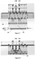
- Figures 5 and 6 show a second configuration in which the gripper mechanisms 34 are again in two groups of six C, D.
- the gripper mechanisms 34 are equidistant in each group and closely spaced for handling battery plate groups in compression frames 40.
- Figures 7 and 8 show a third configuration in which the gripper mechanisms 34 are again closely spaced but in a single group of 12 with a space 42 in the middle of the group so that the gripper mechanisms 34 align properly with the spaces in a jigbox 44 for the groups of plates.
- the space 42 is created by separating the second and third configurable gripper modules 14b, 14c to provide the required spacing.
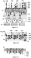
- Figures 9 and 10 show a fourth configuration in which the gripper mechanisms 34 are more widely spaced in a single group of six with a space 46 in the middle of the group so that the gripper mechanisms 34 align properly with the spaces in a jigbox 48 for the groups of plates.
- this configuration only the configurable gripper modules 14a - 14c are used, with the gripper mechanisms 34 set for thicker stacks of plates 50.
- the space 46 is created by separating the gripper units 30a, 30b of the second configurable gripper module 14b to provide the required spacing.
- the unused fixed gripper modules 16a - 16f are moved to the respective ends of the rack 12 so as not to interfere with the configurable modules 14a - 14c.
- Figures 11 - 13 show a fifth configuration for use with pairs of groups to be loaded into compression frames for use in a 3x2 space box.
- the configurable gripper modules 14a - 14c are used and the unused fixed gripper modules 16a - 16f are moved to the respective ends of the rack 12 so as not to interfere with the configurable modules 14a - 14c.
- the sub-racks 28 of each configurable gripper module 14a - 14c are rotated through 90° by rotation of the shaft 24 so as to be perpendicular to the rack 12 so that pairs of gripper mechanisms 34 are aligned transversely to the rack 12.
- Each configurable gripper module 14a - 14c is aligned with a respective compression frame 52a - 52c, each having a pair of receptacles for battery plate groups.
- the boxes 54 into which the groups are to be loaded have six spaces in a 3x2 arrangement and are indexed below the configurable gripper modules 14a - 14c and compression frames 52a - 52c such that each configurable gripper module/compression frame combination aligns with a different row of the spaces in a box. Moving a box 54 to each location successively means that each pair of spaces can be placed below a configurable gripper module/compression frame combination.
- the number of fixed and configurable gripper modules can be selected according to requirements.
- the number of gripper units on each sub-rack can be selected depending on operation requirements.
- Other changes can also be made.
Landscapes
- Engineering & Computer Science (AREA)
- Manufacturing & Machinery (AREA)
- Chemical & Material Sciences (AREA)
- Chemical Kinetics & Catalysis (AREA)
- Electrochemistry (AREA)
- General Chemical & Material Sciences (AREA)
- Mechanical Engineering (AREA)
- Secondary Cells (AREA)
- Battery Mounting, Suspending (AREA)
Applications Claiming Priority (1)
| Application Number | Priority Date | Filing Date | Title |
|---|---|---|---|
| GB2400060.6A GB2637005B (en) | 2024-01-03 | 2024-01-03 | Battery plate handling apparatus and method |
Publications (2)
| Publication Number | Publication Date |
|---|---|
| EP4583221A2 true EP4583221A2 (de) | 2025-07-09 |
| EP4583221A3 EP4583221A3 (de) | 2025-08-13 |
Family
ID=89843863
Family Applications (1)
| Application Number | Title | Priority Date | Filing Date |
|---|---|---|---|
| EP24222922.7A Pending EP4583221A3 (de) | 2024-01-03 | 2024-12-23 | Batterieplattenhandhabungsvorrichtung und -verfahren |
Country Status (3)
| Country | Link |
|---|---|
| US (1) | US20250136389A1 (de) |
| EP (1) | EP4583221A3 (de) |
| GB (1) | GB2637005B (de) |
Citations (1)
| Publication number | Priority date | Publication date | Assignee | Title |
|---|---|---|---|---|
| EP3783712A1 (de) | 2019-08-20 | 2021-02-24 | TBS Engineering Limited | Entladevorrichtung |
Family Cites Families (4)
| Publication number | Priority date | Publication date | Assignee | Title |
|---|---|---|---|---|
| AT8261U1 (de) * | 2004-11-22 | 2006-04-15 | Goger Doris | Verfahren und anlage zum verbinden von batterieplatten zu paketen und zum einsetzen dieser pakete in batteriekästen |
| KR101509206B1 (ko) * | 2013-07-23 | 2015-04-10 | (주)이티에이치 | 그립퍼의 교체가 용이한 전지 충방전용 지그 |
| KR102517823B1 (ko) * | 2021-09-13 | 2023-04-04 | 주식회사 바에솔 | 지그재그형 이차전지의 극판 고속 적층 장치 |
| CN218052660U (zh) * | 2022-08-18 | 2022-12-16 | 襄阳新兴联机械有限公司 | 电池极板入槽夹具 |
-
2024
- 2024-01-03 GB GB2400060.6A patent/GB2637005B/en active Active
- 2024-12-23 EP EP24222922.7A patent/EP4583221A3/de active Pending
-
2025
- 2025-01-02 US US19/007,748 patent/US20250136389A1/en active Pending
Patent Citations (1)
| Publication number | Priority date | Publication date | Assignee | Title |
|---|---|---|---|---|
| EP3783712A1 (de) | 2019-08-20 | 2021-02-24 | TBS Engineering Limited | Entladevorrichtung |
Also Published As
| Publication number | Publication date |
|---|---|
| US20250136389A1 (en) | 2025-05-01 |
| GB202400060D0 (en) | 2024-02-14 |
| GB2637005B (en) | 2026-03-25 |
| GB2637005A (en) | 2025-07-09 |
| EP4583221A3 (de) | 2025-08-13 |
Similar Documents
| Publication | Publication Date | Title |
|---|---|---|
| US11597611B2 (en) | Unloading apparatus | |
| JP2023089293A (ja) | 第1および第2の区分および第2の区分における持上デバイスモータを伴うコンテナ取扱車両 | |
| US4509252A (en) | Method and apparatus for assembling battery components | |
| RU2411608C1 (ru) | Способ формирования штабелей легируемых с одной стороны полупроводниковых пластин, в частности солнечных полупроводниковых пластин, и система манипулирования для загрузки технологической лодочки партиями полупроводниковых пластин | |
| US8756798B2 (en) | Device for fitting and equipping motor vehicle battery housing | |
| CN210339581U (zh) | 一种铅酸电池双线堆垛系统 | |
| CN214114093U (zh) | 电池顶盖片电极柱自动批量上料机构 | |
| CN113734669A (zh) | 双机械手半导体智能仓储以及物流管理方法 | |
| EP4583221A2 (de) | Batterieplattenhandhabungsvorrichtung und -verfahren | |
| CN216661761U (zh) | 一种料盘循环装置 | |
| CN209896036U (zh) | 用于电池片上料的上料机构 | |
| JP2019021607A (ja) | 搬送装置 | |
| CN114871114B (zh) | 电子部件测试用分选机 | |
| CN113113656B (zh) | 交互进料型动力电池切叠一体机及电芯切叠成型方法 | |
| CN211997821U (zh) | 一种托盘自动上下料系统 | |
| CN215120494U (zh) | 转子轴组装装置 | |
| CN117142107B (zh) | 一种电芯配对系统及配对方法 | |
| CN219859252U (zh) | 一种电芯批量上下料设备 | |
| CN214421585U (zh) | 一种电芯生产线 | |
| CN212858953U (zh) | 一种工件输送分类设备及工件加工系统 | |
| CN112591428B (zh) | 一种小规格物料转料机 | |
| EP2377789A1 (de) | Eiertransportvorrichtung in Parallelogrammform | |
| CN209071295U (zh) | 一种电池片料盒输送切换装置 | |
| CN218230921U (zh) | 一种芯片盘自动上下料装置 | |
| CN222040965U (zh) | 计数装置 |
Legal Events
| Date | Code | Title | Description |
|---|---|---|---|
| PUAI | Public reference made under article 153(3) epc to a published international application that has entered the european phase |
Free format text: ORIGINAL CODE: 0009012 |
|
| STAA | Information on the status of an ep patent application or granted ep patent |
Free format text: STATUS: THE APPLICATION HAS BEEN PUBLISHED |
|
| AK | Designated contracting states |
Kind code of ref document: A2 Designated state(s): AL AT BE BG CH CY CZ DE DK EE ES FI FR GB GR HR HU IE IS IT LI LT LU LV MC ME MK MT NL NO PL PT RO RS SE SI SK SM TR |
|
| PUAL | Search report despatched |
Free format text: ORIGINAL CODE: 0009013 |
|
| AK | Designated contracting states |
Kind code of ref document: A3 Designated state(s): AL AT BE BG CH CY CZ DE DK EE ES FI FR GB GR HR HU IE IS IT LI LT LU LV MC ME MK MT NL NO PL PT RO RS SE SI SK SM TR |
|
| RIC1 | Information provided on ipc code assigned before grant |
Ipc: H01M 10/04 20060101AFI20250710BHEP Ipc: H01M 10/14 20060101ALI20250710BHEP Ipc: H01M 10/12 20060101ALI20250710BHEP Ipc: B65G 47/90 20060101ALI20250710BHEP |
|
| STAA | Information on the status of an ep patent application or granted ep patent |
Free format text: STATUS: REQUEST FOR EXAMINATION WAS MADE |
|
| 17P | Request for examination filed |
Effective date: 20251120 |