EP4583095A1 - E-ink-bildschirm und steuerungsverfahren und -vorrichtung dafür sowie computerlesbares speichermedium - Google Patents
E-ink-bildschirm und steuerungsverfahren und -vorrichtung dafür sowie computerlesbares speichermedium Download PDFInfo
- Publication number
- EP4583095A1 EP4583095A1 EP22957262.3A EP22957262A EP4583095A1 EP 4583095 A1 EP4583095 A1 EP 4583095A1 EP 22957262 A EP22957262 A EP 22957262A EP 4583095 A1 EP4583095 A1 EP 4583095A1
- Authority
- EP
- European Patent Office
- Prior art keywords
- time period
- refresh
- preset
- frame
- voltage signal
- Prior art date
- Legal status (The legal status is an assumption and is not a legal conclusion. Google has not performed a legal analysis and makes no representation as to the accuracy of the status listed.)
- Pending
Links
Images
Classifications
-
- G—PHYSICS
- G02—OPTICS
- G02F—OPTICAL DEVICES OR ARRANGEMENTS FOR THE CONTROL OF LIGHT BY MODIFICATION OF THE OPTICAL PROPERTIES OF THE MEDIA OF THE ELEMENTS INVOLVED THEREIN; NON-LINEAR OPTICS; FREQUENCY-CHANGING OF LIGHT; OPTICAL LOGIC ELEMENTS; OPTICAL ANALOGUE/DIGITAL CONVERTERS
- G02F1/00—Devices or arrangements for the control of the intensity, colour, phase, polarisation or direction of light arriving from an independent light source, e.g. switching, gating or modulating; Non-linear optics
- G02F1/01—Devices or arrangements for the control of the intensity, colour, phase, polarisation or direction of light arriving from an independent light source, e.g. switching, gating or modulating; Non-linear optics for the control of the intensity, phase, polarisation or colour
- G02F1/165—Devices or arrangements for the control of the intensity, colour, phase, polarisation or direction of light arriving from an independent light source, e.g. switching, gating or modulating; Non-linear optics for the control of the intensity, phase, polarisation or colour based on translational movement of particles in a fluid under the influence of an applied field
- G02F1/166—Devices or arrangements for the control of the intensity, colour, phase, polarisation or direction of light arriving from an independent light source, e.g. switching, gating or modulating; Non-linear optics for the control of the intensity, phase, polarisation or colour based on translational movement of particles in a fluid under the influence of an applied field characterised by the electro-optical or magneto-optical effect
- G02F1/167—Devices or arrangements for the control of the intensity, colour, phase, polarisation or direction of light arriving from an independent light source, e.g. switching, gating or modulating; Non-linear optics for the control of the intensity, phase, polarisation or colour based on translational movement of particles in a fluid under the influence of an applied field characterised by the electro-optical or magneto-optical effect by electrophoresis
-
- G—PHYSICS
- G02—OPTICS
- G02F—OPTICAL DEVICES OR ARRANGEMENTS FOR THE CONTROL OF LIGHT BY MODIFICATION OF THE OPTICAL PROPERTIES OF THE MEDIA OF THE ELEMENTS INVOLVED THEREIN; NON-LINEAR OPTICS; FREQUENCY-CHANGING OF LIGHT; OPTICAL LOGIC ELEMENTS; OPTICAL ANALOGUE/DIGITAL CONVERTERS
- G02F1/00—Devices or arrangements for the control of the intensity, colour, phase, polarisation or direction of light arriving from an independent light source, e.g. switching, gating or modulating; Non-linear optics
- G02F1/01—Devices or arrangements for the control of the intensity, colour, phase, polarisation or direction of light arriving from an independent light source, e.g. switching, gating or modulating; Non-linear optics for the control of the intensity, phase, polarisation or colour
- G02F1/165—Devices or arrangements for the control of the intensity, colour, phase, polarisation or direction of light arriving from an independent light source, e.g. switching, gating or modulating; Non-linear optics for the control of the intensity, phase, polarisation or colour based on translational movement of particles in a fluid under the influence of an applied field
- G02F1/1675—Constructional details
- G02F1/16757—Microcapsules
-
- G—PHYSICS
- G02—OPTICS
- G02F—OPTICAL DEVICES OR ARRANGEMENTS FOR THE CONTROL OF LIGHT BY MODIFICATION OF THE OPTICAL PROPERTIES OF THE MEDIA OF THE ELEMENTS INVOLVED THEREIN; NON-LINEAR OPTICS; FREQUENCY-CHANGING OF LIGHT; OPTICAL LOGIC ELEMENTS; OPTICAL ANALOGUE/DIGITAL CONVERTERS
- G02F1/00—Devices or arrangements for the control of the intensity, colour, phase, polarisation or direction of light arriving from an independent light source, e.g. switching, gating or modulating; Non-linear optics
- G02F1/01—Devices or arrangements for the control of the intensity, colour, phase, polarisation or direction of light arriving from an independent light source, e.g. switching, gating or modulating; Non-linear optics for the control of the intensity, phase, polarisation or colour
- G02F1/165—Devices or arrangements for the control of the intensity, colour, phase, polarisation or direction of light arriving from an independent light source, e.g. switching, gating or modulating; Non-linear optics for the control of the intensity, phase, polarisation or colour based on translational movement of particles in a fluid under the influence of an applied field
- G02F1/1685—Operation of cells; Circuit arrangements affecting the entire cell
-
- G—PHYSICS
- G09—EDUCATION; CRYPTOGRAPHY; DISPLAY; ADVERTISING; SEALS
- G09G—ARRANGEMENTS OR CIRCUITS FOR CONTROL OF INDICATING DEVICES USING STATIC MEANS TO PRESENT VARIABLE INFORMATION
- G09G3/00—Control arrangements or circuits, of interest only in connection with visual indicators other than cathode-ray tubes
- G09G3/20—Control arrangements or circuits, of interest only in connection with visual indicators other than cathode-ray tubes for presentation of an assembly of a number of characters, e.g. a page, by composing the assembly by combination of individual elements arranged in a matrix no fixed position being assigned to or needed to be assigned to the individual characters or partial characters
- G09G3/34—Control arrangements or circuits, of interest only in connection with visual indicators other than cathode-ray tubes for presentation of an assembly of a number of characters, e.g. a page, by composing the assembly by combination of individual elements arranged in a matrix no fixed position being assigned to or needed to be assigned to the individual characters or partial characters by control of light from an independent source
- G09G3/3433—Control arrangements or circuits, of interest only in connection with visual indicators other than cathode-ray tubes for presentation of an assembly of a number of characters, e.g. a page, by composing the assembly by combination of individual elements arranged in a matrix no fixed position being assigned to or needed to be assigned to the individual characters or partial characters by control of light from an independent source using light modulating elements actuated by an electric field and being other than liquid crystal devices and electrochromic devices
- G09G3/344—Control arrangements or circuits, of interest only in connection with visual indicators other than cathode-ray tubes for presentation of an assembly of a number of characters, e.g. a page, by composing the assembly by combination of individual elements arranged in a matrix no fixed position being assigned to or needed to be assigned to the individual characters or partial characters by control of light from an independent source using light modulating elements actuated by an electric field and being other than liquid crystal devices and electrochromic devices based on particles moving in a fluid or in a gas, e.g. electrophoretic devices
-
- G—PHYSICS
- G09—EDUCATION; CRYPTOGRAPHY; DISPLAY; ADVERTISING; SEALS
- G09G—ARRANGEMENTS OR CIRCUITS FOR CONTROL OF INDICATING DEVICES USING STATIC MEANS TO PRESENT VARIABLE INFORMATION
- G09G2310/00—Command of the display device
- G09G2310/06—Details of flat display driving waveforms
- G09G2310/066—Waveforms comprising a gently increasing or decreasing portion, e.g. ramp
-
- G—PHYSICS
- G09—EDUCATION; CRYPTOGRAPHY; DISPLAY; ADVERTISING; SEALS
- G09G—ARRANGEMENTS OR CIRCUITS FOR CONTROL OF INDICATING DEVICES USING STATIC MEANS TO PRESENT VARIABLE INFORMATION
- G09G2310/00—Command of the display device
- G09G2310/06—Details of flat display driving waveforms
- G09G2310/068—Application of pulses of alternating polarity prior to the drive pulse in electrophoretic displays
-
- G—PHYSICS
- G09—EDUCATION; CRYPTOGRAPHY; DISPLAY; ADVERTISING; SEALS
- G09G—ARRANGEMENTS OR CIRCUITS FOR CONTROL OF INDICATING DEVICES USING STATIC MEANS TO PRESENT VARIABLE INFORMATION
- G09G2320/00—Control of display operating conditions
- G09G2320/02—Improving the quality of display appearance
- G09G2320/0257—Reduction of after-image effects
-
- G—PHYSICS
- G09—EDUCATION; CRYPTOGRAPHY; DISPLAY; ADVERTISING; SEALS
- G09G—ARRANGEMENTS OR CIRCUITS FOR CONTROL OF INDICATING DEVICES USING STATIC MEANS TO PRESENT VARIABLE INFORMATION
- G09G2320/00—Control of display operating conditions
- G09G2320/04—Maintaining the quality of display appearance
- G09G2320/043—Preventing or counteracting the effects of ageing
- G09G2320/046—Dealing with screen burn-in prevention or compensation of the effects thereof
-
- G—PHYSICS
- G09—EDUCATION; CRYPTOGRAPHY; DISPLAY; ADVERTISING; SEALS
- G09G—ARRANGEMENTS OR CIRCUITS FOR CONTROL OF INDICATING DEVICES USING STATIC MEANS TO PRESENT VARIABLE INFORMATION
- G09G2340/00—Aspects of display data processing
- G09G2340/04—Changes in size, position or resolution of an image
- G09G2340/0407—Resolution change, inclusive of the use of different resolutions for different screen areas
- G09G2340/0435—Change or adaptation of the frame rate of the video stream
-
- G—PHYSICS
- G09—EDUCATION; CRYPTOGRAPHY; DISPLAY; ADVERTISING; SEALS
- G09G—ARRANGEMENTS OR CIRCUITS FOR CONTROL OF INDICATING DEVICES USING STATIC MEANS TO PRESENT VARIABLE INFORMATION
- G09G3/00—Control arrangements or circuits, of interest only in connection with visual indicators other than cathode-ray tubes
- G09G3/20—Control arrangements or circuits, of interest only in connection with visual indicators other than cathode-ray tubes for presentation of an assembly of a number of characters, e.g. a page, by composing the assembly by combination of individual elements arranged in a matrix no fixed position being assigned to or needed to be assigned to the individual characters or partial characters
- G09G3/2007—Display of intermediate tones
- G09G3/2011—Display of intermediate tones by amplitude modulation
Definitions
- the present disclosure relates to the technical field of display, and in particular to an electronic ink screen, a control method for the electronic ink screen, a control device for the electronic ink screen, and a computer-readable storage media.
- Each electronic ink capsule in the electronic ink screen typically stores first color particles with positive charges (such as white particles) and second color particles with negative charges (such as black particles).
- first color particles with positive charges such as white particles
- second color particles with negative charges such as black particles.
- a color displayed by the electronic ink capsule may be controlled by applying different voltages (such as a positive voltage or a negative voltage) to the electronic ink capsule.
- a drawback of the existing technology is that in response to the electronic ink capsule displaying the same color or similar color for a long time, it is easy to apply the positive voltage or the negative voltage to the electronic ink capsule for a long time. In this case, the electronic ink capsule is prone to irreversible damage, which leads to more serious ghosting in the electronic ink screen, resulting in poor display effect of the electronic ink screen.
- the main technical problem solved by the present disclosure is how to reduce a ghosting phenomenon of an electronic ink screen, so as to improve a display effect of the electronic ink screen.
- a first technical solution adopted in the present disclosure is providing a control method for an electronic ink screen.
- the electronic ink screen includes a plurality of electronic ink capsules, each of the plurality of the electronic ink capsules includes first color particles with positive charges and second color particles with negative charges, an amplitude range of a control voltage signal corresponding to the plurality of electronic ink capsules is from a preset maximum negative voltage value to a preset maximum positive voltage value, and one of the plurality of electronic ink capsules is used as a target capsule.
- the control method includes: ensuring that a difference between the number of times of positive voltage refresh processes corresponding to the target capsule and the number of times of negative voltage refresh processes corresponding to the target capsule in a preset time period is less than or equal to a preset difference threshold.
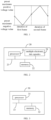
- Each of the positive voltage refresh processes includes: increasing an amplitude of the control voltage signal to the preset maximum positive voltage value, and then reducing the amplitude of the control voltage signal, so that the target capsule displays a color based on the control voltage signal to complete a refresh of one frame.
- Each of the negative voltage refresh processes includes: reducing the amplitude of the control voltage signal to the preset maximum negative voltage value, and then increasing the amplitude of the control voltage signal, so that the target capsule displays the color based on the control voltage signal to complete the refresh of one frame.
- the ensuring that a difference between the number of times of positive voltage refresh processes corresponding to the target capsule and the number of times of negative voltage refresh processes corresponding to the target capsule in a preset time period is less than or equal to a preset difference threshold includes: ensuring that the number of times of the positive voltage refresh processes corresponding to the target capsule is equal to the number of times of the negative voltage refresh processes corresponding to the target capsule in the preset time period.
- the preset time period is a time period corresponding to two frames, and one frame of the two frames is defined as a first frame and the other frame of the two frames is defined as a second frame.
- the ensuring that a difference between the number of times of positive voltage refresh processes corresponding to the target capsule and the number of times of negative voltage refresh processes corresponding to the target capsule in a preset time period is less than or equal to a preset difference threshold includes: in a time period corresponding to the first frame, increasing the amplitude of the control voltage signal to the preset maximum positive voltage value, and then reducing the amplitude of the control voltage signal, so that the target capsule displays the color based on the control voltage signal to complete the refresh of the first frame; and in a time period corresponding to the second frame, reducing the amplitude of the control voltage signal to the preset maximum negative voltage value, and then increasing the amplitude of the control voltage signal, so that the target capsule displays the color based on the control voltage signal to complete the refresh of one frame.
- executing the positive voltage refresh process of the positive voltage number of times, and executing the negative voltage refresh process of the negative voltage number of times further includes: controlling the target capsule to complete refresh of each frame that has not been refreshed in the second time period based on the negative voltage refresh process in response to the number of times that the positive voltage refresh process in the second time period is executed reaching the positive voltage number of times, and controlling the target capsule to complete the refresh of each frame that has not been refreshed in the second time period based on the positive voltage refresh process in response to the number of times that the negative voltage refresh process is executed in the second time period reaching the negative voltage number of times.
- a duration of the preset time period is less than or equal to a duration corresponding to preset quantity of frames.
- a second technical solution adopted in the present disclosure is providing a control device for an electronic ink screen.
- the electronic ink screen includes a plurality of electronic ink capsules, each of the plurality of the electronic ink capsules includes first color particles with positive charges and second color particles with negative charges, an amplitude range of a control voltage signal corresponding to the plurality of electronic ink capsules is from a preset maximum negative voltage value to a preset maximum positive voltage value, and one of the plurality of electronic ink capsules is used as a target capsule.
- the control device includes: a control unit, configured to ensure that a difference between the number of times of positive voltage refresh processes corresponding to the target capsule and the number of times of negative voltage refresh processes corresponding to the target capsule in a preset time period is less than or equal to a preset difference threshold.
- Each of the positive voltage refresh processes includes: increasing an amplitude of the control voltage signal to the preset maximum positive voltage value, and then reducing the amplitude of the control voltage signal, so that the target capsule displays a color based on the control voltage signal, so as to complete refresh of one frame.
- Each of the negative voltage refresh processes includes: reducing the amplitude of the control voltage signal to the preset maximum negative voltage value, and then increasing the amplitude of the control voltage signal, so that the target capsule displays the color based on the control voltage signal, so as to complete the refresh of one frame.
- control unit is configured for: ensuring that the number of times of the positive voltage refresh processes corresponding to the target capsule is equal to the number of times of the negative voltage refresh processes corresponding to the target capsule in the preset time period.
- control unit is configured for: in the time period corresponding to the first frame, reducing the amplitude of the control voltage signal to the preset maximum negative voltage value, and then increasing the amplitude of the control voltage signal, so that the target capsule displays the color based on the control voltage signal to complete the refresh of the first frame; and in the time period corresponding to the second frame, increasing the amplitude of the control voltage signal to the preset maximum positive voltage value, and then increasing the amplitude of the control voltage signal, so that the target capsule displays the color based on the control voltage signal to complete the refresh of one frame.
- the preset time period includes a first time period and a second time period, and a difference between a duration of the first time period and a duration of the second time period is less than or equal to a preset time difference threshold.
- the control unit is configured for: controlling the target capsule to display the color of each frame based on the positive voltage refresh process in the first time period, and controlling the target capsule to display the color of each frame based on the negative voltage refresh process in the second time period.
- the difference between the number of times of the positive voltage refresh processes corresponding to the target capsule and the number of times of the negative voltage refresh processes corresponding to the target capsule in the preset time period is less than or equal to the preset difference threshold.
- the number of times of the positive voltage refresh processes corresponding to the target capsule is close to the number of times of the negative voltage refresh processes corresponding to the target capsule.
- the number of times that the amplitude of the control voltage signal received by the target capsule reaches the maximum positive voltage value is close to the number of times that the amplitude of the control voltage signal received by the target capsule reaches the maximum negative voltage value.
- the terms “installation”, “setting”, and “connection” should be broadly understood.
- it may be a fixed connection, a detachable connection, or an integrated connection; it may be a mechanical connection or an electrical connection; it may be a direct connection or an indirect connection through an intermediate medium.
- the specific meanings of the above term may be understood according to specific circumstances.
- the present disclosure first provides a control method for an electronic ink screen, which is applied to the electronic ink screen.
- the electronic ink screen may include multiple electronic ink capsules, the multiple electronic ink capsules may be arranged in an array on a substrate of the electronic ink screen or arranged in other ways.
- the specific arrangement of the multiple electronic ink capsules may be determined according to actual needs and is not limited here.
- FIG. 6 is a structural schematic view of the electronic ink screen in an embodiment of the present disclosure. As illustrated in FIG. 6 , in an embodiment, the electronic ink screen 10 includes multiple electronic ink capsules 11, and the multiple electronic ink capsules 11 include a target capsule 111.
- a single electronic ink capsule includes first color particles with positive charges and second color particles with negative charges.
- the single electronic ink capsule may include white particles with positive charges and black particles with negative charges, or the single electronic ink capsule may include black particles with positive charges and white particles with negative charges.
- the color of the first color particles and the color of the second color particles may also be a combination of other colors, which may be determined according to actual needs and are not limited here.
- One of the multiple electronic ink capsules may be used as a target capsule, and the control method for the electronic ink screen includes the following operations.
- the control method for the electronic ink screen may include ensuring that a difference between the number of times of positive voltage refresh processes corresponding to the target capsule and the number of times of negative voltage refresh processes corresponding to the target capsule in a preset time period is less than or equal to a preset difference threshold.
- a single positive voltage refresh process includes the following operations.
- the amplitude of the control voltage signal received by the target capsule may be increased until the amplitude reaches the preset maximum positive voltage value. Then, the amplitude of the control voltage signal reaching the preset maximum positive voltage value may be reduced until the amplitude reaches a target voltage value corresponding to the target color, so that the target capsule may display the target color based on the control voltage signal of the target voltage value, completing the refresh of one frame corresponding to the target capsule.
- the target color is the color that the target capsule needs to display in the current frame.
- a single negative voltage refresh process includes the following operations.
- the target capsule may avoid the situation where the target capsule receives the positive voltage signal or the negative voltage signal for a long time, so as to reduce the possibility of damage to the electronic ink capsule of the electronic ink screen, thereby slowing down the occurrence of the ghosting phenomenon in the electronic ink screen and improving the display effect of the electronic ink screen.
- the operation S11 may include the following operations.
- the amplitude of the control voltage signal is increased to the preset maximum positive voltage value, and then the amplitude of the control voltage signal is reduced, so that the target capsule displays the color based on the control voltage signal to complete the refresh of the first frame.
- the amplitude of the control voltage signal is reduced to the preset maximum negative voltage value, and then the amplitude of the control voltage signal is increased, so that the target capsule displays the color based on the control voltage signal to complete the refresh of one frame.
- the amplitude of the control voltage signal is reduced to the preset maximum negative voltage value, and then the amplitude of the control voltage signal is increased, so that the target capsule displays the color based on the control voltage signal to complete the refresh of the first frame.
- the amplitude of the control voltage signal is increased to the preset maximum positive voltage value, and then the amplitude of the control voltage signal is increased, so that the target capsule displays the color based on the control voltage signal to complete the refresh of one frame.
- the positive voltage refresh process in response to the preset time period including and only including the time period corresponding to the first frame and the time period corresponding to the second frame, the positive voltage refresh process may be executed in any one of these two time periods to complete the refresh of the corresponding frame, and the negative voltage refresh process may be executed in the other time period of these two time periods to complete the refresh of the corresponding frame.
- the time period for completing the positive voltage refresh process may be the time period corresponding to the first frame, or the time period corresponding to the second frame, which is not limited here.
- the target capsule may respectively execute one positive voltage refresh process and one negative voltage refresh process in the time periods corresponding to any two adjacent frames. That is, the target capsule respectively receives one positive voltage control voltage signal and one negative voltage control voltage signal in the time periods corresponding to any two adjacent frames.
- the target capsule may continuously maintain a state where the number of times that the amplitude of the received control voltage signal reaches the maximum positive voltage value is equal to the number of times that the amplitude of the received control voltage signal reaches the maximum negative voltage value.
- the target capsule may continuously maintain a state where the number of times that the amplitude of the received control voltage signal reaches the maximum positive voltage value differs by one from the number of times that the amplitude of the received control voltage signal reaches the maximum negative voltage value.
- the preset time period includes the first time period and the second time period, and a difference between a duration of the first time period and a duration of the second time period is less than or equal to a preset time difference threshold.
- the operation S11 may include the following operation: controlling the target capsule to display the color of each frame based on the positive voltage refresh process in the first time period, and controlling the target capsule to display the color of each frame based on the negative voltage refresh process in the second time period.
- the amplitude of the control voltage signal received by the target capsule in the time period corresponding to each frame in the first time period, is first increased to the preset maximum positive voltage value and then reduced to the target voltage value based on the positive voltage refresh process, so as to display the corresponding color.
- the amplitude of the control voltage signal received by the target capsule is first reduced to the preset maximum negative voltage value and then increased to the target voltage value based on the negative voltage refresh process, so as to display the corresponding color.
- the number of times that the target capsule receives the positive control voltage signal is equal to the number of times that the target capsule receives the negative control voltage signal, thereby minimizing the possibility of damage to the electronic ink capsule of the electronic ink screen and improving the display effect of the electronic ink screen.
- the preset time period includes the first time period and the second time period.
- the number of frames in the time period corresponding to the first time period is equal to the number of frames in the time period corresponding to the second time period.
- the time period corresponding to the first time period is in the time period corresponding to the second time period.
- the operation S11 may include the following operation: determining the number of times that the positive voltage refresh process needs to be executed in the second time period based on the number of times that the negative voltage refresh process is executed in the first time period, and recording the number of times that the positive voltage refresh process needs to be executed in the second time period as a positive voltage number of times; and determining the number of times that the negative voltage refresh process needs to be executed in the second time period based on the number of times that the positive voltage refresh process is executed in the first time period, and recording the number of times that the negative voltage refresh process needs to be executed in the second time period as a negative voltage number of times.
- the positive voltage refresh process of the positive voltage number of times is executed, and the negative voltage refresh process of the negative voltage number of times is executed.
- the operation S11 may further include the following operation: in the first time period, determining a value closest to the current amplitude of the control voltage signal in the preset maximum negative voltage value and the preset maximum positive voltage value in response to the target capsule displaying the color based on the control voltage signal to complete the refresh of one frame, wherein the negative voltage refresh process is executed in response to the closest value being the preset maximum negative voltage value, and the positive voltage refresh process is executed in response to the closest value being the preset maximum positive voltage value, so as to complete the refresh of the next frame.
- a difference between the current amplitude and the preset maximum positive voltage value and a difference between the current amplitude and the preset maximum negative voltage value may be determined.
- the minimum difference may be determined, and one of the preset maximum positive voltage value and the preset maximum negative voltage value corresponding to the minimum difference is determined as the value closest to the amplitude of the control voltage signal.
- the fastest refresh of the target capsule in the first time period may be performed.
- the number of times that the corresponding positive voltage refresh process and the negative voltage refresh process need to be executed may still be determined according to the number of times that the positive voltage refresh process and the negative voltage refresh process are executed in the first time period. It may ensure a balance between the number of times of the positive voltage refresh process corresponding to the target capsule and the number of times of the negative voltage refresh process corresponding to the target capsule. Thus, the ghosting phenomenon in the electronic ink screen is reduced and the display effect of the electronic ink screen is improved.
- it may further maximize the refresh speed corresponding to some frames in the second time period, and ensure the balance between the number of times of the positive voltage refresh process corresponding to the target capsule and the number of times of the negative voltage refresh process corresponding to the target capsule.
- the ghosting phenomenon in the electronic ink screen is reduced and the display effect of the electronic ink screen is improved.
- a ratio of the preset difference threshold to the number of times of the positive voltage refresh processes in the preset time period is recorded as a first ratio
- a ratio of the preset difference threshold to the number of times of the negative voltage refresh processes in the preset time period is recorded as a second ratio.
- the first ratio is less than or equal to a preset ratio threshold, and/or, the second ratio is less than or equal to the preset ratio threshold.
- the preset ratio threshold is assumed to be 0.1, in response to the number of times of the positive voltage refresh processes in the preset time period being 10 times, the first ratio less than or equal to 0.1 means that the preset difference threshold is less than or equal to 1 time. Similarly, in response to the number of times of the negative voltage refresh processes in the preset time period being 20 times, the second ratio less than or equal to 0.1 means that the preset difference threshold is less than or equal to 2 times.
- the above values are only examples, and may be other values, which is not limited here.
- the preset difference threshold may adaptively adjust the preset difference threshold according to the number of times of the positive voltage refresh processes and/or the number of times of the negative voltage refresh processes in the preset time period, avoiding the preset difference threshold being too large or too small relative to the number of times of the positive voltage refresh processes and/or the number of times of the negative voltage refresh processes in the preset time period. Therefore, the difference between the number of times of the positive voltage and the number of times of the negative voltage received by the electronic ink capsule in the preset time period is avoided to be too large, which further improves the reliability of the above methods for controlling the electronic ink screen and improves the display effect of the electronic ink screen.
- the duration of the preset time period is less than or equal to the duration corresponding to the preset quantity of frames.
- it may avoid the preset time period of too long, so as to avoid the damage caused by the target capsule receiving continuous positive voltage or negative voltage for too long in the preset time period.
- the longer the usage duration of the target capsule the higher the possibility of damage to the target capsule due to receiving continuous positive voltage or negative voltage. Therefore, the preset quantity may be negatively correlated with the usage duration of the target capsule, which further reduces the possibility of damage to the target capsule and improve the display effect of the electronic ink screen.
- the usage duration of a capsule with the longest usage duration in the multiple electronic ink capsules is recorded as a target usage duration. There is a negative correlation between the preset quantity and the target usage duration.
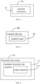
- the present disclosure further provides an electronic ink screen, as illustrated in FIG. 2 ,
- FIG. 2 is a structural schematic view of an electronic ink screen in an embodiment of the present disclosure.
- the electronic ink screen 20 includes a processor 21, a memory 22, a bus 23, and multiple electronic ink capsules 24.
- the multiple electronic ink capsules 24 may be the multiple electronic ink capsules as described in any one of above embodiments, which is not repeated here.
- the processor 21, the memory 22, and the multiple electronic ink capsules 24 are respectively connected to the bus 23.
- the memory 22 stores a program instruction
- the processor 21 is configured to execute the program instruction to implement the control method for the electronic ink screen in any one of the above embodiments.
- the difference between the number of times of the positive voltage refresh processes corresponding to the target capsule and the number of times of the negative voltage refresh processes corresponding to the target capsule in the preset time period is less than or equal to the preset difference threshold.
- the number of times of the positive voltage refresh processes corresponding to the target capsule is close to the number of times of the negative voltage refresh processes corresponding to the target capsule.
- the number of times that the amplitude of the control voltage signal received by the target capsule reaches the maximum positive voltage value is close to the number of times that the amplitude of the control voltage signal received by the target capsule reaches the maximum negative voltage value.
- FIG. 3 is a structural schematic view of a control device for the electronic ink screen in an embodiment of the present disclosure.
- the electronic ink screen 30 includes a processor 31, a memory 32, and a bus 33.
- the electronic ink screen includes the multiple electronic ink capsules as described in any one of above embodiments, which is not repeated here.
- the processor 31 and the memory 32 are respectively connected to the bus 33, the memory 32 stores the program instruction.
- the processor 31 is configured to execute the program instruction to implement the control method for the electronic ink screen in any one of the above embodiments.
- the processor 31 may also be referred to as the central processing unit (CPU).
- the processor 31 may be the integrated circuit chip with the signal processing capability.
- the processor 31 may also be the general-purpose processor, the digital signal processor (DSP), the application-specific integrated circuit (ASIC), the field programmable gate array (FPGA) or other programmable logic devices, discrete gates or transistor logic devices, or discrete hardware components.
- DSP digital signal processor
- ASIC application-specific integrated circuit
- FPGA field programmable gate array
- the general-purpose processor may be the microprocessor or the processor 31 may also be any conventional processor, etc.
- the difference between the number of times of the positive voltage refresh processes corresponding to the target capsule and the number of times of the negative voltage refresh processes corresponding to the target capsule in the preset time period is less than or equal to the preset difference threshold.
- the number of times of the positive voltage refresh processes corresponding to the target capsule is close to the number of times of the negative voltage refresh processes corresponding to the target capsule.
- the number of times that the amplitude of the control voltage signal received by the target capsule reaches the maximum positive voltage value is close to the number of times that the amplitude of the control voltage signal received by the target capsule reaches the maximum negative voltage value.
- the target capsule may avoid the situation where the target capsule receives the positive voltage signal or the negative voltage signal for a long time, so as to reduce the possibility of damage to the electronic ink capsule of the electronic ink screen, thereby slowing down the occurrence of the ghosting phenomenon in the electronic ink screen and improving the display effect of the electronic ink screen.
- FIG. 4 is a structural schematic view of a computer-readable storage medium in an embodiment of the present disclosure.
- the computer-readable storage medium 40 stores a program instruction 41, and the control method for the electronic ink screen is implemented in response to the program instruction 41 being executed by the processor (not shown in FIG. 4 ).
- the computer-readable storage medium 40 may be, but not limited to, a USB flash drive, a SD card, a PD optical drive, a mobile hard disk, a large capacity floppy drive, a flash memory, a multimedia memory card, or a server, etc.
- the difference between the number of times of the positive voltage refresh processes corresponding to the target capsule and the number of times of the negative voltage refresh processes corresponding to the target capsule in the preset time period is less than or equal to the preset difference threshold.
- the number of times of the positive voltage refresh processes corresponding to the target capsule is close to the number of times of the negative voltage refresh processes corresponding to the target capsule.
- the number of times that the amplitude of the control voltage signal received by the target capsule reaches the maximum positive voltage value is close to the number of times that the amplitude of the control voltage signal received by the target capsule reaches the maximum negative voltage value.
- the target capsule may avoid the situation where the target capsule receives the positive voltage signal or the negative voltage signal for a long time, so as to reduce the possibility of damage to the electronic ink capsule of the electronic ink screen, thereby slowing down the occurrence of the ghosting phenomenon in the electronic ink screen and improving the display effect of the electronic ink screen.
- the present disclosure further provides a control device for the electronic ink screen.
- the electronic ink screen includes the multiple electronic ink capsules.
- the electronic ink capsules include the first color particles with the positive charges and the second color particles with the negative charges.
- the amplitude range of the control voltage signal corresponding to the electronic ink capsule is from the preset maximum negative voltage value to the preset maximum positive voltage value.
- One of the multiple electronic ink capsules is used as the target capsule.
- FIG. 5 is a structural schematic view of a control device for the electronic ink screen in an embodiment of the present disclosure.
- the control device 50 includes a control unit 51.
- the control unit 51 is configured to ensure that the difference between the number of times of the positive voltage refresh processes corresponding to the target capsule and the number of times of the negative voltage refresh processes corresponding to the target capsule in the preset time period is less than or equal to the preset difference threshold.
Landscapes
- Physics & Mathematics (AREA)
- Nonlinear Science (AREA)
- General Physics & Mathematics (AREA)
- Optics & Photonics (AREA)
- Engineering & Computer Science (AREA)
- Theoretical Computer Science (AREA)
- Computer Hardware Design (AREA)
- Health & Medical Sciences (AREA)
- Life Sciences & Earth Sciences (AREA)
- Chemical & Material Sciences (AREA)
- Chemical Kinetics & Catalysis (AREA)
- Electrochemistry (AREA)
- Molecular Biology (AREA)
- Control Of Indicators Other Than Cathode Ray Tubes (AREA)
- Electrochromic Elements, Electrophoresis, Or Variable Reflection Or Absorption Elements (AREA)
Applications Claiming Priority (2)
| Application Number | Priority Date | Filing Date | Title |
|---|---|---|---|
| CN202211041269.5A CN115116403B (zh) | 2022-08-29 | 2022-08-29 | 电子墨水屏及其控制方法、装置和计算机可读存储介质 |
| PCT/CN2022/143541 WO2024045453A1 (zh) | 2022-08-29 | 2022-12-29 | 电子墨水屏及其控制方法、装置和计算机可读存储介质 |
Publications (2)
| Publication Number | Publication Date |
|---|---|
| EP4583095A1 true EP4583095A1 (de) | 2025-07-09 |
| EP4583095A4 EP4583095A4 (de) | 2025-09-10 |
Family
ID=83336125
Family Applications (1)
| Application Number | Title | Priority Date | Filing Date |
|---|---|---|---|
| EP22957262.3A Pending EP4583095A4 (de) | 2022-08-29 | 2022-12-29 | E-ink-bildschirm und steuerungsverfahren und -vorrichtung dafür sowie computerlesbares speichermedium |
Country Status (5)
| Country | Link |
|---|---|
| US (1) | US12142234B2 (de) |
| EP (1) | EP4583095A4 (de) |
| KR (1) | KR20250038800A (de) |
| CN (1) | CN115116403B (de) |
| WO (1) | WO2024045453A1 (de) |
Families Citing this family (3)
| Publication number | Priority date | Publication date | Assignee | Title |
|---|---|---|---|---|
| CN115116403B (zh) * | 2022-08-29 | 2023-01-31 | 惠科股份有限公司 | 电子墨水屏及其控制方法、装置和计算机可读存储介质 |
| CN116246589A (zh) * | 2023-02-28 | 2023-06-09 | 联想(北京)有限公司 | 控制方法、装置、设备及存储介质 |
| CN117854444B (zh) * | 2023-08-14 | 2024-07-09 | 广州文石信息科技有限公司 | 墨水屏的显示控制方法、装置、电子设备以及存储介质 |
Family Cites Families (31)
| Publication number | Priority date | Publication date | Assignee | Title |
|---|---|---|---|---|
| US5446483A (en) * | 1993-04-19 | 1995-08-29 | Advanced Micro Devices, Inc. | Variable speed controller for an electronic display |
| JP4474822B2 (ja) * | 2002-05-21 | 2010-06-09 | ソニー株式会社 | 表示素子の駆動方法 |
| CN101800034B (zh) * | 2002-06-13 | 2013-03-06 | 伊英克公司 | 用于寻址双稳电光媒质的方法 |
| KR20070121403A (ko) * | 2006-06-22 | 2007-12-27 | 삼성전자주식회사 | 전기 영동 표시 장치 및 그 제조 방법 |
| US20080303780A1 (en) * | 2007-06-07 | 2008-12-11 | Sipix Imaging, Inc. | Driving methods and circuit for bi-stable displays |
| JP5320724B2 (ja) * | 2007-11-06 | 2013-10-23 | セイコーエプソン株式会社 | 電気泳動表示シート、電気泳動表示装置および電子機器 |
| JP2009236603A (ja) * | 2008-03-26 | 2009-10-15 | Seiko Epson Corp | 温度センサ、温度センサの製造方法、電気泳動装置、および電子機器 |
| US8462102B2 (en) * | 2008-04-25 | 2013-06-11 | Sipix Imaging, Inc. | Driving methods for bistable displays |
| TWI409767B (zh) * | 2010-03-12 | 2013-09-21 | Sipix Technology Inc | 電泳顯示器的驅動方法 |
| JP5382540B2 (ja) * | 2010-04-22 | 2014-01-08 | セイコーエプソン株式会社 | 電気泳動装置の駆動方法、電気泳動装置を制御するためのコントローラ、電気泳動装置、電子機器、および電子時計 |
| US9984608B2 (en) * | 2014-06-25 | 2018-05-29 | Apple Inc. | Inversion balancing compensation |
| CN105070254A (zh) * | 2015-08-31 | 2015-11-18 | 深圳市国华光电科技有限公司 | 一种多级灰阶电泳电子纸的快速响应方法 |
| CN105632417B (zh) | 2016-01-14 | 2019-02-15 | 北京大上科技有限公司 | 电子墨水屏幕残影清除方法、显示方法及相应的电子设备 |
| CN108476306B (zh) * | 2016-12-30 | 2021-04-20 | 华为技术有限公司 | 一种图像显示的方法及终端设备 |
| US10395583B1 (en) * | 2017-01-27 | 2019-08-27 | Amazon Technologies, Inc. | Driving a display for presenting electronic content |
| CN107068071A (zh) * | 2017-05-16 | 2017-08-18 | 华南师范大学 | 一种电泳显示器减弱纹理的方法及系统 |
| CN107342057A (zh) * | 2017-08-09 | 2017-11-10 | 京东方科技集团股份有限公司 | 用于驱动电泳显示面板的方法、装置以及显示装置 |
| CN107315283B (zh) * | 2017-08-17 | 2021-03-05 | 京东方科技集团股份有限公司 | 背光模组、显示装置和调节背光模组出光亮度的方法 |
| CN108847190B (zh) * | 2018-07-10 | 2020-11-03 | 福州大学 | 一种电润湿电子纸显示器的驱动方法 |
| CN110596262A (zh) * | 2019-08-14 | 2019-12-20 | 中国农业科学院蜜蜂研究所 | 利用液相色谱串联质谱测定蜂蜜中意蜂mrjp1蛋白含量的方法 |
| CN111508440B (zh) * | 2020-03-25 | 2021-05-25 | 广州奥翼材料与器件研究院有限公司 | 一种电泳显示器的驱动方法 |
| WO2022082555A1 (en) * | 2020-10-22 | 2022-04-28 | Qualcomm Incorporated | Dynamic frame rate optimization |
| CN113593466B (zh) * | 2021-05-18 | 2024-02-09 | 昆山国显光电有限公司 | 显示面板的驱动方法、显示装置及存储介质 |
| CN113380201B (zh) * | 2021-06-22 | 2023-06-30 | 北京京东方光电科技有限公司 | 电子纸显示屏及其显示控制方法、电子纸显示装置 |
| CN113870801A (zh) * | 2021-09-28 | 2021-12-31 | 青岛海信移动通信技术股份有限公司 | 刷新墨水屏的方法和终端设备 |
| CN113917758B (zh) * | 2021-10-18 | 2024-07-30 | 京东方科技集团股份有限公司 | 一种电子纸显示装置及其驱动方法 |
| CN114023272B (zh) * | 2021-11-12 | 2022-10-14 | 青岛海信移动通信技术股份有限公司 | 消除墨水屏残影的方法和终端设备 |
| CN114527611B (zh) * | 2021-12-30 | 2023-09-26 | 广东志慧芯屏科技有限公司 | 电子纸显示装置的制作方法 |
| CN114446252B (zh) * | 2022-03-10 | 2022-12-09 | 惠科股份有限公司 | 电泳显示设备及电泳显示刷新方法 |
| CN114724521A (zh) * | 2022-04-29 | 2022-07-08 | 重庆京东方智慧电子系统有限公司 | 显示面板和显示装置 |
| CN115116403B (zh) * | 2022-08-29 | 2023-01-31 | 惠科股份有限公司 | 电子墨水屏及其控制方法、装置和计算机可读存储介质 |
-
2022
- 2022-08-29 CN CN202211041269.5A patent/CN115116403B/zh active Active
- 2022-12-29 WO PCT/CN2022/143541 patent/WO2024045453A1/zh not_active Ceased
- 2022-12-29 KR KR1020257005964A patent/KR20250038800A/ko active Pending
- 2022-12-29 EP EP22957262.3A patent/EP4583095A4/de active Pending
-
2024
- 2024-06-23 US US18/751,255 patent/US12142234B2/en active Active
Also Published As
| Publication number | Publication date |
|---|---|
| JP2025520769A (ja) | 2025-07-03 |
| US20240347015A1 (en) | 2024-10-17 |
| KR20250038800A (ko) | 2025-03-19 |
| CN115116403B (zh) | 2023-01-31 |
| WO2024045453A1 (zh) | 2024-03-07 |
| US12142234B2 (en) | 2024-11-12 |
| CN115116403A (zh) | 2022-09-27 |
| EP4583095A4 (de) | 2025-09-10 |
Similar Documents
| Publication | Publication Date | Title |
|---|---|---|
| EP4583095A1 (de) | E-ink-bildschirm und steuerungsverfahren und -vorrichtung dafür sowie computerlesbares speichermedium | |
| CN113377485B (zh) | 墨水屏设备的刷新显示方法、电子设备及存储介质 | |
| CN112114975B (zh) | 处理器频率的调整方法、装置、存储介质及电子设备 | |
| US10798334B2 (en) | Image processing system, image display method, display device and storage medium | |
| US11094296B2 (en) | Varying display refresh rate | |
| CN103500039B (zh) | 触摸显示屏及其驱动方法 | |
| US9990891B2 (en) | Control device, display device, and method of controlling display device | |
| KR101668569B1 (ko) | 화상 데이터 출력 제어 장치, 표시 장치, 및 프로그램이 기록되어 있는 컴퓨터 판독가능한 기록 매체 | |
| EP3348965B1 (de) | Verfahren, vorrichtung zum plotten eines navigationsgraphen und speichermedium dafür | |
| EP3069345B1 (de) | System und verfahren zur verringerung der e/a-speicherleistung über datenmaskierung | |
| CN110164355B (zh) | 控制信号输出电路及方法、阵列基板、显示装置 | |
| CN105353937A (zh) | 一种显示界面的控制方法及终端 | |
| CN102004541A (zh) | 图像显示系统及方法 | |
| CN107767837B (zh) | 驱动调整电路及调整方法、显示装置 | |
| JP7854074B2 (ja) | 電子インクスクリーン及びその制御方法、装置、及びコンピュータ可読記憶媒体 | |
| JP7742499B2 (ja) | 異形スクリーンの表示回路及び表示装置 | |
| US11393420B2 (en) | Display device, pixel circuit and its driving method and driving device | |
| CN117456953A (zh) | 显示面板的伽马调节方法、装置及电子设备 | |
| US11495184B2 (en) | Control method of electronic ink screen, display control device and electronic ink display apparatus | |
| WO2024022190A1 (zh) | 显示驱动方法、显示基板和显示装置 | |
| US9202426B2 (en) | Display driving circuit and driving method of display unit | |
| JPWO2010106576A1 (ja) | 不揮発性液晶表示装置および、不揮発性液晶表示装置の表示方法 | |
| CN119418624B (zh) | 驱动电路及其控制方法、显示面板、控制器及显示装置 | |
| WO2026011713A1 (zh) | 一种电泳显示面板的驱动方法、驱动电路、电泳显示面板及计算机程序产品 | |
| CN116682380A (zh) | 数据驱动电路、显示面板、驱动强度调节方法及存储介质 |
Legal Events
| Date | Code | Title | Description |
|---|---|---|---|
| STAA | Information on the status of an ep patent application or granted ep patent |
Free format text: STATUS: THE INTERNATIONAL PUBLICATION HAS BEEN MADE |
|
| PUAI | Public reference made under article 153(3) epc to a published international application that has entered the european phase |
Free format text: ORIGINAL CODE: 0009012 |
|
| STAA | Information on the status of an ep patent application or granted ep patent |
Free format text: STATUS: REQUEST FOR EXAMINATION WAS MADE |
|
| 17P | Request for examination filed |
Effective date: 20240528 |
|
| AK | Designated contracting states |
Kind code of ref document: A1 Designated state(s): AL AT BE BG CH CY CZ DE DK EE ES FI FR GB GR HR HU IE IS IT LI LT LU LV MC ME MK MT NL NO PL PT RO RS SE SI SK SM TR |
|
| A4 | Supplementary search report drawn up and despatched |
Effective date: 20250808 |
|
| RIC1 | Information provided on ipc code assigned before grant |
Ipc: G09G 3/34 20060101AFI20250804BHEP Ipc: G02F 1/1685 20190101ALI20250804BHEP Ipc: G02F 1/16757 20190101ALI20250804BHEP |
|
| DAV | Request for validation of the european patent (deleted) | ||
| DAX | Request for extension of the european patent (deleted) |