EP4582878A2 - Kartusche und bilderzeugungsvorrichtung - Google Patents
Kartusche und bilderzeugungsvorrichtung Download PDFInfo
- Publication number
- EP4582878A2 EP4582878A2 EP25171868.0A EP25171868A EP4582878A2 EP 4582878 A2 EP4582878 A2 EP 4582878A2 EP 25171868 A EP25171868 A EP 25171868A EP 4582878 A2 EP4582878 A2 EP 4582878A2
- Authority
- EP
- European Patent Office
- Prior art keywords
- cartridge
- section
- contact
- electrode
- resin material
- Prior art date
- Legal status (The legal status is an assumption and is not a legal conclusion. Google has not performed a legal analysis and makes no representation as to the accuracy of the status listed.)
- Pending
Links
Images


Classifications
-
- G—PHYSICS
- G03—PHOTOGRAPHY; CINEMATOGRAPHY; ANALOGOUS TECHNIQUES USING WAVES OTHER THAN OPTICAL WAVES; ELECTROGRAPHY; HOLOGRAPHY
- G03G—ELECTROGRAPHY; ELECTROPHOTOGRAPHY; MAGNETOGRAPHY
- G03G21/00—Arrangements not provided for by groups G03G13/00 - G03G19/00, e.g. cleaning, elimination of residual charge
- G03G21/16—Mechanical means for facilitating the maintenance of the apparatus, e.g. modular arrangements
- G03G21/18—Mechanical means for facilitating the maintenance of the apparatus, e.g. modular arrangements using a processing cartridge, whereby the process cartridge comprises at least two image processing means in a single unit
- G03G21/1839—Means for handling the process cartridge in the apparatus body
- G03G21/1867—Means for handling the process cartridge in the apparatus body for electrically connecting the process cartridge to the apparatus, electrical connectors, power supply
-
- G—PHYSICS
- G03—PHOTOGRAPHY; CINEMATOGRAPHY; ANALOGOUS TECHNIQUES USING WAVES OTHER THAN OPTICAL WAVES; ELECTROGRAPHY; HOLOGRAPHY
- G03G—ELECTROGRAPHY; ELECTROPHOTOGRAPHY; MAGNETOGRAPHY
- G03G15/00—Apparatus for electrographic processes using a charge pattern
- G03G15/80—Details relating to power supplies, circuits boards, electrical connections
-
- G—PHYSICS
- G03—PHOTOGRAPHY; CINEMATOGRAPHY; ANALOGOUS TECHNIQUES USING WAVES OTHER THAN OPTICAL WAVES; ELECTROGRAPHY; HOLOGRAPHY
- G03G—ELECTROGRAPHY; ELECTROPHOTOGRAPHY; MAGNETOGRAPHY
- G03G21/00—Arrangements not provided for by groups G03G13/00 - G03G19/00, e.g. cleaning, elimination of residual charge
- G03G21/16—Mechanical means for facilitating the maintenance of the apparatus, e.g. modular arrangements
- G03G21/1642—Mechanical means for facilitating the maintenance of the apparatus, e.g. modular arrangements for connecting the different parts of the apparatus
- G03G21/1652—Electrical connection means
-
- G—PHYSICS
- G03—PHOTOGRAPHY; CINEMATOGRAPHY; ANALOGOUS TECHNIQUES USING WAVES OTHER THAN OPTICAL WAVES; ELECTROGRAPHY; HOLOGRAPHY
- G03G—ELECTROGRAPHY; ELECTROPHOTOGRAPHY; MAGNETOGRAPHY
- G03G21/00—Arrangements not provided for by groups G03G13/00 - G03G19/00, e.g. cleaning, elimination of residual charge
- G03G21/16—Mechanical means for facilitating the maintenance of the apparatus, e.g. modular arrangements
- G03G21/18—Mechanical means for facilitating the maintenance of the apparatus, e.g. modular arrangements using a processing cartridge, whereby the process cartridge comprises at least two image processing means in a single unit
- G03G21/1803—Arrangements or disposition of the complete process cartridge or parts thereof
- G03G21/1814—Details of parts of process cartridge, e.g. for charging, transfer, cleaning, developing
-
- G—PHYSICS
- G03—PHOTOGRAPHY; CINEMATOGRAPHY; ANALOGOUS TECHNIQUES USING WAVES OTHER THAN OPTICAL WAVES; ELECTROGRAPHY; HOLOGRAPHY
- G03G—ELECTROGRAPHY; ELECTROPHOTOGRAPHY; MAGNETOGRAPHY
- G03G2221/00—Processes not provided for by group G03G2215/00, e.g. cleaning or residual charge elimination
- G03G2221/16—Mechanical means for facilitating the maintenance of the apparatus, e.g. modular arrangements and complete machine concepts
- G03G2221/1651—Mechanical means for facilitating the maintenance of the apparatus, e.g. modular arrangements and complete machine concepts for connecting the different parts
- G03G2221/166—Electrical connectors
-
- G—PHYSICS
- G03—PHOTOGRAPHY; CINEMATOGRAPHY; ANALOGOUS TECHNIQUES USING WAVES OTHER THAN OPTICAL WAVES; ELECTROGRAPHY; HOLOGRAPHY
- G03G—ELECTROGRAPHY; ELECTROPHOTOGRAPHY; MAGNETOGRAPHY
- G03G2221/00—Processes not provided for by group G03G2215/00, e.g. cleaning or residual charge elimination
- G03G2221/16—Mechanical means for facilitating the maintenance of the apparatus, e.g. modular arrangements and complete machine concepts
- G03G2221/18—Cartridge systems
- G03G2221/183—Process cartridge
Definitions
- the drum flanges are portions that are rotationally borne and supported by the respective bearing portions.
- the charging roller 66 and the cleaning member 77 of the cleaning unit 60 are in contact with the outer circumferential surface of the drum 62.
- the cleaning member 77 has a rubber blade 77a, which is a blade-shaped elastic member made of rubber as an elastic material, and a support member 77b supporting the rubber blade.
- the rubber blade 77a substantially extends in the direction opposite to the rotation direction of the drum 62 and is in contact with the drum 62. That is, the rubber blade 77a is in contact with the drum 62 with its distal edge pointing toward the upstream side in the rotation direction R of the drum 62.
- the waste toner removed from the surface of the drum 62 by the cleaning member 77 is stored in the waste toner chamber 71b defined by the cleaning frame 71 and the cleaning member 77.
- the developing unit 20 is rotationally (pivotally) connected to the cleaning unit 60. That is, the developing roller 32 is coupled to the drum 62 so as to be movable toward and away from the drum 62. Then, the drum bearing 73 is coupled to the cleaning unit 60 to form the cartridge B.
- FIG. 6A is a cross-sectional view of the drive-side guide portion of the image forming apparatus A for illustrating the attachment of the cartridge B.
- FIG. 6B is a cross-sectional view of the non-drive-side guide portion of the image forming apparatus A for illustrating the attachment of the cartridge B.
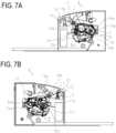
- FIG. 7A is a cross-sectional view of the drive side of the image forming apparatus A for illustrating the positioning of the cartridge B.
- FIG. 7B is a cross-sectional view of the non-drive side of the image forming apparatus A for illustrating the positioning of the cartridge B.
- a first drive-side plate 15 includes an upper guide rail 15g and a guide rail 15h as guides, and a non-drive-side plate 16 includes an upper guide rail 16d and a guide rail 16e.
- the drum bearing 73 provided on the drive side of the cartridge B has a rotation stop target portion 73c.
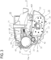
- the cartridge B is attached in a direction (arrow C) substantially perpendicular to the axis of the drum 62 ( FIG. 3 ).
- the cleaning frame 71 includes, on the non-drive side in the longitudinal direction, a positioning target portion 71d as a first positioning portion and a rotation stop target portion 71f as a second positioning portion.
- the guide rail 15h of the apparatus main body A guides the rotation stop target portion 73c of the cartridge B on the drive side of the cartridge B.
- the guide rails 16d and 16e of the apparatus main body A guide the positioning target portion 71d and the rotation stop target portion 71f of the cartridge B. The cartridge B is thus attached to the apparatus main body A.
- FIG. 14 is an enlarged view for illustrating the configuration of the conductive portion 1701 in detail.
- the conductive portion 1701 includes a connection section 1701e for connecting the contact section 1701a and the conductive support section 1701b.
- the conductive portion 1701 and the non-conductive portion 1702 are formed by two-color molding, and the conductive portion 1701 has a section that is formed by the resin that has spread on one side of the non-conductive portion 1702 in the longitudinal direction and a section that is formed by the resin that has spread on the other side in the molding.
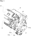
- the cleaning unit 60 has a cleaning frame 71, which serves as a first frame.
- the charging roller 66 which serves as a process unit, is provided inside the cleaning frame 71.
- an electrode plate 82 which electrically connects the charging roller 66 to the apparatus main body, is attached to the side surface of the cleaning frame 71 on the non-drive side.
- the cleaning frame 71 is made of a material having a density of about 0.95 to 1.10 g/cm 3 and a flame retardancy of HB according to the UL94 standard.
- the cleaning frame 71 supports the charging roller 66 as a rotational rotating member through the charging roller bearing 67.
- the replenishing operation of the toner cartridges 2550 is performed when the toner level detection unit (not shown) installed in the apparatus main body of the image forming apparatus 2600 detects a shortage of toner remaining in the process cartridges 2500.
- the toner cartridges 2550 can be attached to and detached from the image for apparatus 2600 through an attachment unit such as an attachment guide (not shown) and a positioning member (not shown) provided in the image forming apparatus 2600.
- the process cartridges 2500 will be described in detail below.
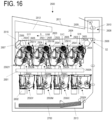
- First to fourth toner transport devices 2602 are arranged under the toner cartridges 2550 corresponding to the respective toner cartridges 2550. Each toner transport device 2602 transports the toner received from the toner cartridge 2550 upward to supply the toner to the corresponding developing unit 2502.
- An intermediate transfer unit 2604 which serves as an intermediate transfer member, is provided above the process cartridges 2500. The intermediate transfer unit 2604 is arranged substantially horizontally with its primary transfer portion S1 on the lower side.
- An intermediate transfer belt 2603 which is a rotational endless belt, faces the photosensitive drums 2503 and is stretched over a plurality of tension rollers.
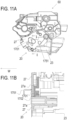
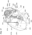
- FIG. 17 is a schematic cross-sectional view of a process cartridge according to the present embodiment.
- a photosensitive drum 2503 is driven to rotate at a predetermined speed in the direction of arrow a in FIG. 17 .
- the intermediate transfer belt 2603 is driven to rotate in the direction of arrow b in FIG. 16 (in the forward direction of the rotation of the photosensitive drum 2503).
- the charging roller 2504 uniformly charges the surface of the photosensitive drum 2503. Then, a laser beam is emitted from the scanner unit 2601 to the surface of the photosensitive drum 2503 for scanning exposure, thereby forming an electrostatic latent image on the photosensitive drum 2503 according to image information.
- the electrostatic latent image formed on the photosensitive drum 2503 is developed as a toner image (developer image) by the developing unit 2502.
- the developing unit 2502 is pressurized by the development pressure unit (not shown) provided in the main body of the image forming apparatus 2600.
- the toner image formed on the photosensitive drum 2503 is transferred, as primary transfer, onto the intermediate transfer belt 2603 by the primary transfer roller 2605.
- the recording material 2700 to which the toner image is transferred is transported to the fixing unit 2608.
- the fixing unit 2608 applies heat and pressure to the recording material 2700 thereby fixing the toner image on the recording material 2700.
- the recording material 2700 is transported to the discharge tray 2611 to complete the image forming operation.
- the cleaning blades 2505 remove the primary-transfer residual toner (waste toner) remaining on the photosensitive drums 2503 after the primary transfer step.
- the intermediate transfer belt cleaning unit 2607 removes the secondary-transfer residual toner (waste toner) remaining on the intermediate transfer belt 2603 after the secondary transfer step.
- the waste toner removed by the cleaning blades 2505 and the intermediate transfer belt cleaning unit 2607 is transported by a waste toner transport unit 2616 provided in the apparatus main body and stored in the waste toner collection container 2612.
- the image forming apparatus 2600 can also form a monochromatic or multicolor image by using only one or some (but not all) desired image forming portions.
- FIG. 17 is a schematic cross-sectional view of a process cartridge 2500 according to the present embodiment.
- FIG. 18A is a perspective view of the process cartridge 2500 as viewed from the bottom surface side.
- FIG. 18B is a perspective view of the process cartridge 2500 as viewed from the top surface side.
- the process cartridge 2500 includes a cleaning unit 2501 and a developing unit 2502.
- the cleaning unit 2501 and the developing unit 2502 are connected so as to be pivotal about a rotation support pin 2507.
- the cleaning unit 2501 includes a cleaning frame 2508, which supports various members in the cleaning unit 2501.
- the cleaning unit 2501 includes a waste toner screw 2509 extending parallel to the rotation axis of the photosensitive drum 2503.
- the cleaning frame 2508 includes cleaning bearings 2511, which rotationally support the photosensitive drum 2503 at opposite longitudinal ends of the cleaning unit 2501.
- the cleaning bearings 2511 include cleaning gear trains for transmitting drive from the photosensitive drum 2503 to the waste toner screw 2509.
- the charging roller 2504 is urged toward the photosensitive drum 2503 in the direction of arrow c by charging roller pressure springs 2512 arranged at both ends.
- the charging roller 2504 is provided so as to be driven by the photosensitive drum 2503.
- the charging roller 2504 is rotated in the direction of arrow d (forward direction of the rotation of the photosensitive drum 2503).
- the cleaning blade 2505 includes an elastic member 2505a for removing transfer residual toner (waste toner) remaining on the surface of the photosensitive drum 2503 after primary transfer, and a support member 2505b for supporting the elastic member 2505a.
- the waste toner removed from the surface of the photosensitive drum 2503 by the cleaning blade 2505 is stored in a waste toner storage chamber 2513 defined by the cleaning blade 2505 and the cleaning frame 2508.
- the waste toner screw 2509 in the waste toner storage chamber 2513 transports the waste toner stored in the waste toner storage chamber 2513 rearward of the image forming apparatus 2600 (downstream side in the attachment/detachment direction of the process cartridge 2500).
- the transported waste toner is discharged through a waste toner discharge portion 2618 and delivered to the waste toner transport unit 2616 of the image forming apparatus 2600.
- the developing unit 2502 has a development frame 2614, which supports various members of the developing unit 2502.
- the development frame 2614 is partitioned into a developing chamber 2514a, which accommodates a developing roller 2506 and a supply roller 2515, and a toner storage chamber 2514b, which stores toner and accommodates an agitation member 2516.
- the developing chamber 2514a accommodates the developing roller 2506, the supply roller 2515, and a development blade 2517.
- the developing roller 2506 carries toner as a developer carrying member, rotates in the direction of arrow e during image formation, and transports the toner to the photosensitive drum 2503 by coming into contact with the photosensitive drum 2503.
- the developing roller 2506 is rotationally supported by the development frame 2514 through development bearing units 2518 at its opposite ends in the longitudinal direction (rotation axis direction).
- the supply roller 2515 which serves as a developer supply member, is rotationally supported by the development frame 2514 through the development bearing units 2518 so as to be rotatable in contact with the developing roller 2506.
- the supply roller 2515 rotates in the direction of arrow f during image formation.
- the development blade 2517 which serves as a layer thickness controlling member that controls the thickness of the toner layer formed on the developing roller 2506, is arranged in contact with the surface of the developing roller 2506.
- the toner storage chamber 2514b accommodates the agitation member 2516, which agitates the stored toner T and transports the toner to the supply roller 2515 through a developing chamber communication port 2514c.
- the agitation member 2516 includes a rotation shaft 2516a, which is parallel to the rotation axis of the developing roller 2506, and an agitation sheet 2516b, which is flexible and serves as a transport member.
- One edge of the agitation sheet 2516b is fixed to the rotation shaft 2516a, and the other edge of the agitation sheet 2516b is a free edge.
- the agitation sheet 2516b rotates in the direction of arrow g when the rotation shaft 2516a rotates, so that the toner is agitated by the agitation sheet 2516b.
- the developing unit 2502 has the developing chamber communication port 2514c, which provides communication between the developing chamber 2514a and the toner storage chamber 2514b.
- the developing chamber 2514a is located above the toner storage chamber 2514b.
- the toner in the toner storage chamber 2514b that is lifted by the agitation member 2516 is supplied to the developing chamber 2514a through the developing chamber communication port 2514c.
- the developing unit 2502 also has a receiving port 2519 at one end on the downstream side in the attachment/detachment direction.
- a receiving port seal member 2520 and a toner receiving port shutter 2521 which is movable in the front-rear direction, are arranged above the toner receiving port 2519.
- the toner receiving port shutter 2521 closes the toner receiving port 2519.
- the toner receiving port shutter 2521 is configured to be urged and opened by the image forming apparatus 2600 in time with the attachment/detachment operation of the process cartridge 2500.
- a receiving transport passage 2522 is provided in communication with the toner receiving port 2519, and a receiving transport screw 2523 is arranged in the receiving transport passage 2522.
- the protruding section 2529a which is made of a highly flame-retardant material, functions as a fire-spreading prevention wall. This prevents the fire from spreading to the inside of the process cartridge 2500 including the cleaning frame 2508.
- the drum unit 2808 and the developing unit 2809 are coupled to each other.
- a detailed description of the process cartridge 2800 will be given below.
- the first process cartridge 2800Y contains yellow (Y) toner in the development frame 2825 and forms a yellow toner image on the surface of the photosensitive drum 2804.
- the second process cartridge 2800M contains magenta (M) toner in the development frame 2825 and forms a magenta toner image on the surface of the photosensitive drum 2804.
- the third process cartridge 2800C contains cyan (C) toner in the development frame 2825 and forms a cyan toner image on the surface of the photosensitive drum 2804.
- the fourth process cartridge 2800K contains black (K) toner in the development frame 2825 and forms a black toner image on the surface of the photosensitive drum 2804.
- a laser scanner unit 2714 which serves as an exposure unit, is provided above the first to fourth process cartridges 2800 (2800Y, 2800M, 2800C, and 2800K).
- the laser scanner unit 2714 outputs a laser beam L according to image information.
- the laser beam L passes through an exposure window 2810 of the process cartridge 2800 and performs scanning exposure on the surface of the photosensitive drum 2804.
- An intermediate transfer unit 2712 as a transfer member is provided under the first to fourth process cartridges 2800 (2800Y, 2800M, 2800C, and 2800K).
- the intermediate transfer unit 2712 includes a drive roller 2712e, a turn roller 2712c, and a tension roller 2712b, and a flexible transfer belt 2712a, which runs around these rollers.
- a secondary transfer roller 2706 is in contact with the drive roller 2712e through the transfer belt 2712a.
- the contact section between the transfer belt 2712a and the secondary transfer roller 2706 serves as the secondary transfer portion.
- a feeding unit 2704 is provided under the intermediate transfer unit 2712.
- the feeding unit 2704 includes a paper feed tray 2704a, which houses recording media S, and a paper feed roller 2704b.
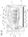
- a fixing apparatus 2707 and a paper ejection device 2708 are provided in the upper left section of the image forming apparatus main body 2870 as viewed in FIG. 23 .
- the upper surface of the image forming apparatus main body 2870 functions as a paper ejection tray 2713.
- a fixing means of the fixing apparatus 2707 fixes the toner image on the recording medium S, which is then ejected onto the paper ejection tray 2713.
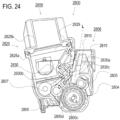
- the operation for forming a full-color image is as follows.
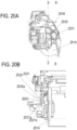
- the photosensitive drum 2804 of each of the first to fourth process cartridges 2800 (2800Y, 2800M, 2800C, and 2800K) is driven to rotate at a predetermined speed (in the direction of arrow A in FIG. 24 ).
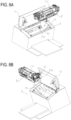
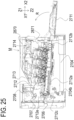
- FIG. 25 is a cross-sectional view of the image forming apparatus M in a state in which the front door 2711 is open and the tray 2871 is located inside the image forming apparatus main body 2870.
- FIG. 26 is a cross-sectional view of the image forming apparatus M in a state in which the front door 2711 is open, the tray 2871 is located outside the image forming apparatus main body 2870, and the process cartridges 2800 are housed inside the tray.
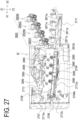
- FIG. 27 is a cross-sectional view of the image forming apparatus M in a state in which the front door 2711 is open, the tray 2871 is located outside the image forming apparatus main body 2870, and the process cartridges 2800 are removed from the tray 2871.
- the tray 2871 is movable relative to the image forming apparatus main body 2870 in the direction of arrow X1 (pushing direction) and the direction of arrow X2 direction (pulling direction), which are substantially horizontal. That is, the tray 2871 is provided such that it can be pulled out of and pushed into the image forming apparatus main body 2870.
- the tray 2871 is movable substantially in horizontal directions.
- a state in which the tray 2871 is located outside the image forming apparatus main body 2870 (the state shown in FIG. 26 ) is referred to as an outside position.
- a state in which the front door 2711 is open, the tray 2871 is located inside the image forming apparatus main body 2870, and the photosensitive drums 2804 are separated from the transfer belt 2712a (state in FIG. 25 ) is referred to as an inside position.
- the tray 2871 includes attachment portions 2871a to which the process cartridges 2800 are removably attached in the outside position.
- the process cartridges 2800 placed in the attachment portions 2871a move into the image forming apparatus main body 2870.
- a gap is maintained between the transfer belt 2712a and each photosensitive drum 2804.
- closing the front door 2711 causes a link mechanism (not shown) to lift the intermediate transfer unit 2712 in the direction of arrow Z1 to the position for image formation (the position at which the intermediate transfer belt 2712a is in contact with the photosensitive drums 2804).
- the tray 2871 can move the process cartridges 2800 into the image forming apparatus main body 2870 without the photosensitive drums 2804 coming into contact with the transfer belt 2712a.
- the tray 2871 allows the plurality of process cartridges 2800 to be moved together to a position in the image forming apparatus main body 2870 at which image formation is possible, and also allows them to be pulled out of the image forming apparatus main body 2870 together.
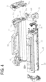
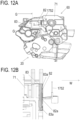
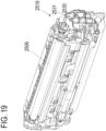
- FIG. 28 is an exploded perspective view of a drum unit 2808.
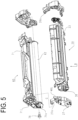
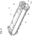
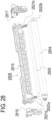
- FIG. 29 is an exploded perspective view of a developing unit 2809.
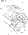
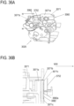
- FIG. 30 is an exploded perspective view of a process cartridge 2800 as viewed from the drive side, which is one end side in the axial direction of the photosensitive drum 2804.
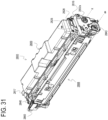
- FIG. 31 is an assembly perspective view of a process cartridge 2800 as viewed from the drive side.
- the first to fourth process cartridges 2800 (2800Y, 2800M, 2800C, and 2800K) have the same electrophotographic process mechanism but contain toner of different colors and amounts.
- Each process cartridge 2800 includes a photosensitive drum 2804 (2804Y, 2804M, 2804C, 2804K) and a process unit acting on the photosensitive drum 2804.
- the process unit includes a charging roller 2805 as a charging unit for charging the photosensitive drum 2804, a developing roller 2806 as a developing unit for developing a latent image formed on the photosensitive drum 2804, and the like.
- the process cartridge 2800 is divided into a drum unit 2808 (2808Y, 2808M, 2808C, 2808K) and a developing unit 2809 (2809Y, 2809M, 2809C, 2809K).
- longitudinal directions (Y1 and Y2 directions) of the drum unit 2808 and the developing unit 2809 are directions substantially parallel to the rotation axis ax of the photosensitive drum 2810.
- the drum unit 2808 includes a photosensitive drum 2804, a charging roller 2805, and a drum frame 2815, which is a first frame.
- the charging roller 2805 is rotationally supported by a drive-side charging roller bearing 2820a and a non-drive-side charging roller bearing 2820b, and is urged toward the photosensitive drum 2804 by pressing springs 2821a and 2821b.
- the photosensitive drum 2804 is rotationally supported by a drive-side cartridge cover member 2816 and a non-drive-side cartridge cover member 2817, which is a second frame, on opposite ends in the longitudinal direction of the process cartridge 2800.
- the non-drive-side cartridge cover member 2817 includes an electrode member 2860, which receives power from the image forming apparatus main body 2870. Details will be described below.
- a coupling member 2843 for transmitting a driving force to the photosensitive drum 2804 is provided at one longitudinal end of the photosensitive drum 2804.
- the coupling member 2843 engages with a main-body drum drive coupling 2880 (see FIG. 26 ), which serves as a drum drive output portion of the image forming apparatus main body 2870.
- the driving force of a drive motor (not shown) of the image forming apparatus main body 2870 is transmitted to the photosensitive drum 2804 through the coupling member 2843, and the photosensitive drum 2804 is rotated in the direction of arrow A ( FIG. 24 ).
- the photosensitive drum 2804 includes a drum flange 2842 at the other longitudinal end.
- the charging roller 2805 is supported by the drum frame 2815 so as to be in contact with and rotated by the photosensitive drum 2804.
- the developing unit 2809 includes a developing roller 2806, a toner transport roller 2807, a development blade 2830, a development frame 2825, and the like.
- the development frame 2825 which serves as a fourth frame (a fourth member), includes a lower frame 2825a and a lid member 2825b.
- the lower frame 2825a and the lid member 2825b have a flame retardancy of HB according to the UL94 standard.
- the lower frame 2825a is joined to the lid member 2825b by ultrasonic welding or the like.
- the development frame 2825 includes a toner storage portion 2829 for storing toner to be supplied to the developing roller 2806.
- the development frame 2825 rotationally supports the developing roller 2806 and toner transport roller 2807 through a drive-side bearing 2826 and a non-drive-side bearing 2827, and holds the development blade 2830, which controls the layer thickness of the toner on the circumference of the developing roller 2806.
- the development blade 2830 is formed by welding or otherwise joining an elastic member 2830b, which is a metal sheet having a thickness of about 0.1 mm, to a support member 2830a, which is a metal material having an L-shaped cross section.
- the development blade 2830 is fixed to the development frame 2825 with fixing screws 2830c at two locations on opposite longitudinal ends.
- the developing roller 2806 includes a metal core bar 2806c and a rubber portion 2806d.
- the developing roller 2806 is rotationally supported by the drive-side bearing 2826 and the non-drive-side bearing 2827, which are attached to opposite longitudinal ends of the development frame 2825.
- a development drive input gear 2832 for transmitting a driving force to the developing unit 2809 is provided at one longitudinal end of the developing unit 2809.
- the development drive input gear 2832 includes a development input coupling portion 2832a, which is driven by a main-body development drive coupling 2885 (see FIG. 26 ) of the image forming apparatus main body 2870.
- the driving force of the drive motor (not shown) of the image forming apparatus main body 2870 is input to the developing unit 2809 through the development input coupling portion 2832a, the development drive input gear 2832, and the like.
- the driving force input to the developing unit 2809 is transmitted to the developing roller gear 2831 so that the developing roller 2806 is rotated in the direction of arrow D in FIG. 24 .
- a development cover member 2828 which supports and covers the development drive input gear 2832, is provided at one longitudinal end of the developing unit 2809.
- the developing roller 2806 has a smaller outer diameter than the photosensitive drum 2804.
- the outer diameter of the photosensitive drum 2804 is in the range of ⁇ 18 to ⁇ 22, and the outer diameter of the developing roller 2806 is in the range of ⁇ 8 to ⁇ 14.
- the drum unit 2808 and the developing unit 2809 are coupled through the drive-side cartridge cover member 2816 and the non-drive-side cartridge cover member 2817 provided at opposite ends of the process cartridge 2800 in the longitudinal direction.
- the developing unit 2809 is supported by the drive-side cartridge cover member 2816 and non-drive-side cartridge cover member 2817 to be rotational relative to the drum unit 2808 (photosensitive drum 2804).
- the developing roller 2806 is thus positioned at a location at which the developing roller 2806 acts on the photosensitive drum 2804 during image formation.
- FIG. 31 shows a state in which the drum unit 2808 and the developing unit 2809 are coupled together through the above steps and integrally formed as the process cartridge 2800.
- the axis connecting the center of the developing unit support hole 2816a of the drive-side cartridge cover member 2816 and the center of the developing unit support hole 2817a of the non-drive-side cartridge cover member 2817 is referred to as a pivot axis K.
- the cylindrical section 2828b of the development cover member 2828 at one end is coaxial with a development input coupling 2774. That is, the developing unit 2809 is configured to receive a driving force from the image forming apparatus main body 2870 transmitted along the pivot axis K. Also, the developing unit 2809 is supported so as to be rotational about the pivot axis K.
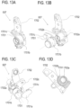
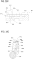
- FIG. 32A is a perspective view of the area around the section of the drum unit 2808 that is coupled to the non-drive-side cartridge cover member 2817.
- FIG. 32A only the electrode member 2860 is shown in an exploded view.
- FIG. 32B is a cross-sectional view of the electrode member 2860.
- FIG. 32C is a cross-sectional view taken along line F-F in FIG. 32A , showing a state in which the electrode member 2860 is fixed in FIG. 32A .
- FIG. 32D is a cross-sectional view taken along line J-J in FIG. 32A , showing a state in which the electrode member 2860 is fixed in FIG. 32A .
- the side of the electrode member 2860 including the contact section 2860c is bent about 3° in the direction of the conductive resin 2818 relative to a setting surface 2860e that is set on the non-drive-side cartridge cover member 2817. This is to prevent the contact section 2860c of the electrode member 2860 from being separated from the surface 2818a of the conductive resin 2818 when the electrode member 2860 is coupled to the non-drive-side cartridge cover member 2817.
- the voltage supplied from the contact spring 2893 to the electrode member 2860 is fed to the charging roller 2805 via the conductive resin 2818, which is formed in the drum frame 2815 by two-color molding, the pressing spring 2821b, and the non-drive-side charging roller bearing 2820b.
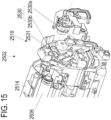
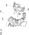
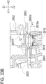
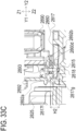
- FIG. 33A is a perspective view of a process cartridge in a state in which a storage element communication unit 2890 and a contact spring holding member 2892 are lowered.
- FIG. 33B is an enlarged cross-sectional view of the power supply portion taken along line V-V in FIG. 33A .
- FIG. 33C is an enlarged cross-sectional view of the power supply portion taken along line N-N in FIG. 33A .
- the image forming apparatus main body 2870 includes the contact spring holding member 2892 and holds the contact spring 2893 for supplying power to the process cartridge 2800.
- the contact spring holding member 2892 is fixed to the storage element communication unit 2890, which communicates with a storage element (not shown) provided in the process cartridge 2800.
- protruding sections 2817f protrude from the non-drive-side cartridge cover member 2817 in the direction of arrow Z1 on opposite sides of the electrode member 2860 (in directions of arrows X1 and X2).
- the height H1 of the protruding sections 2817f is set to be higher than the contact surface 2860d between the contact spring 2893 and the electrode member 2860 in the Z1 direction.
- the protruding sections 2817f are preferably located in the vicinity of the contact spring 2893 and the electrode member 2860.
- a protruding section 2817g is arranged that is integrally connected to the ends in the Y1 direction of the protruding sections 2817f of the non-drive-side cartridge cover member 2817.
- the height H2 of the protruding sections 2817g is set to be higher in the Z1 direction than the contact surface 2860d between the contact spring 2893 and the electrode member 2860.
- the protruding section 2817g is preferably located in the vicinity of the contact spring 2893 and the electrode member 2860.
- protruding sections 2892a and 2892b also extend in the longitudinal direction from the contact spring holding member 2892.
- the protruding sections 2892a and 2892b are set so as to obstruct the fire-spreading range R.
- the fire spreads over the fire-spreading ranges Q' and R'.
- the lack of components that limit the spreading of fire may spread the fire to the development frame 2825, which is made of an HB material with low flame retardancy.
- the present embodiment has the protruding sections 2817f and 2817g of the non-drive-side cartridge cover member 2817 and the protruding sections 2892a and 2892b of the contact spring holding member 2892, which have a flame retardancy of V-1, in the fire-spreading range, the fire does not spread to a component with low flame retardancy.
- the protruding sections 2817f and 2817g of the non-drive-side cartridge cover member 2817 are provided around the electrode member 2860, and the contact spring holding member 2892 having the protruding sections 2892a and 2892b is arranged above the fire-spreading range.
- the non-drive-side cartridge cover member 2817 and the contact spring holding member 2892 are made of a material with a flame retardancy of V-1 according to the UL94 standard. As a result, even if ignition occurs due to tracking, the fire does not spread to parts with low flame retardancy. It is thus possible to provide a process cartridge and an image forming apparatus that ensure safety.
- the protruding sections of the non-drive-side cartridge cover member 2817 surround the electrode member 2860, but the configuration is not limited to this.
- a protruding section may protrude from the contact spring holding member 2892 in the Z2 direction and surround the electrode member 2860.
- the non-drive-side cartridge cover member 2817 and the contact spring holding member 2892 have a flame retardancy of V-1 according to the UL94 standard, but these members may have a flame retardancy of V-1 or higher.
- the process cartridge configuration and the drum cartridge configuration of the first to third embodiments can achieve the same effects of weight reduction and fire spreading prevention in a configuration in which these configurations are bound to the apparatus main body of the image forming apparatus in a nonremovable manner.
- the process cartridge configuration and the drum cartridge configuration of the first to third embodiments are applicable to a configuration in which these configurations are bound to the image forming apparatus in a nonremovable manner.
- the use of an HB material that is a low-density resin material reduces the overall weight of the image forming apparatus, achieving both the safety and weight reduction of the image forming apparatus. As a result, the impact value of the image forming apparatus main body during physical distribution can be lowered. This allows the packaging of the image forming apparatus to be smaller, improving the distribution efficiency.
- a cartridge for an image forming apparatus includes: a process unit to be used to form an image; a first member including a first resin material; a second member including a second resin material having higher flame retardant capability than the first resin material; and an electrode member including a contact section configured to be supplied with power from an apparatus main body of the image forming apparatus.
- the electrode member is configured to electrically connect the apparatus main body to the process unit.
- the second resin material of the second member has a greater density than the first resin material of the first member.
- the contact section is located in the vicinity of the first and second members and is closer to the second member than to the first member.
- This application is a divisional application of European patent application no. 21 193 735.4 (the "parent application"), also published under no. EP 3 961 310 A1 .
- the original claims of the parent application are repeated below in the present specification in the form of items and form part of the content of this divisional application as filed.
Landscapes
- Physics & Mathematics (AREA)
- General Physics & Mathematics (AREA)
- Engineering & Computer Science (AREA)
- Computer Vision & Pattern Recognition (AREA)
- Electrophotography Configuration And Component (AREA)
Applications Claiming Priority (2)
| Application Number | Priority Date | Filing Date | Title |
|---|---|---|---|
| JP2020146225 | 2020-08-31 | ||
| EP21193735.4A EP3961310B1 (de) | 2020-08-31 | 2021-08-30 | Kartusche und bilderzeugungsvorrichtung |
Related Parent Applications (2)
| Application Number | Title | Priority Date | Filing Date |
|---|---|---|---|
| EP21193735.4A Division EP3961310B1 (de) | 2020-08-31 | 2021-08-30 | Kartusche und bilderzeugungsvorrichtung |
| EP21193735.4A Division-Into EP3961310B1 (de) | 2020-08-31 | 2021-08-30 | Kartusche und bilderzeugungsvorrichtung |
Publications (2)
| Publication Number | Publication Date |
|---|---|
| EP4582878A2 true EP4582878A2 (de) | 2025-07-09 |
| EP4582878A3 EP4582878A3 (de) | 2025-09-03 |
Family
ID=77543362
Family Applications (2)
| Application Number | Title | Priority Date | Filing Date |
|---|---|---|---|
| EP21193735.4A Active EP3961310B1 (de) | 2020-08-31 | 2021-08-30 | Kartusche und bilderzeugungsvorrichtung |
| EP25171868.0A Pending EP4582878A3 (de) | 2020-08-31 | 2021-08-30 | Kartusche und bilderzeugungsvorrichtung |
Family Applications Before (1)
| Application Number | Title | Priority Date | Filing Date |
|---|---|---|---|
| EP21193735.4A Active EP3961310B1 (de) | 2020-08-31 | 2021-08-30 | Kartusche und bilderzeugungsvorrichtung |
Country Status (5)
| Country | Link |
|---|---|
| US (3) | US11520286B2 (de) |
| EP (2) | EP3961310B1 (de) |
| JP (2) | JP7171855B2 (de) |
| KR (1) | KR102791389B1 (de) |
| CN (1) | CN114114872B (de) |
Families Citing this family (3)
| Publication number | Priority date | Publication date | Assignee | Title |
|---|---|---|---|---|
| JP7171855B2 (ja) | 2020-08-31 | 2022-11-15 | キヤノン株式会社 | プロセスユニット及び画像形成装置 |
| JP2024002835A (ja) * | 2022-06-24 | 2024-01-11 | キヤノン株式会社 | カートリッジ及び画像形成装置 |
| US20250330559A1 (en) * | 2024-04-22 | 2025-10-23 | Universal City Studios Llc | Multi-sided projection system |
Citations (2)
| Publication number | Priority date | Publication date | Assignee | Title |
|---|---|---|---|---|
| JP2012063750A (ja) | 2010-08-20 | 2012-03-29 | Canon Inc | カートリッジ及び画像形成装置 |
| EP3961310A1 (de) | 2020-08-31 | 2022-03-02 | Canon Kabushiki Kaisha | Kartusche und bilderzeugungsvorrichtung |
Family Cites Families (15)
| Publication number | Priority date | Publication date | Assignee | Title |
|---|---|---|---|---|
| JPS5335485B2 (de) * | 1973-03-13 | 1978-09-27 | ||
| JP3437460B2 (ja) * | 1998-08-31 | 2003-08-18 | キヤノン株式会社 | トナー容器 |
| JP3840063B2 (ja) * | 2001-04-27 | 2006-11-01 | キヤノン株式会社 | プロセスカートリッジ |
| JP2002328581A (ja) * | 2001-04-27 | 2002-11-15 | Canon Inc | 電子写真画像形成装置のカートリッジ |
| JP4373708B2 (ja) | 2003-05-20 | 2009-11-25 | 株式会社リコー | 画像形成装置 |
| US7099607B2 (en) * | 2003-06-18 | 2006-08-29 | Canon Kabushiki Kaisha | Cartridge, and toner container |
| US20070092291A1 (en) * | 2005-10-07 | 2007-04-26 | Canon Kabushiki Kaisha | Cartridge and a process for manufacturing a cartridge |
| JP2007199505A (ja) * | 2006-01-27 | 2007-08-09 | Toshiba Corp | 現像剤補給装置 |
| JP5335485B2 (ja) * | 2009-02-27 | 2013-11-06 | キヤノン株式会社 | プロセスカートリッジ、画像形成装置、及びシール方法 |
| JP5549858B2 (ja) * | 2009-03-05 | 2014-07-16 | 株式会社リコー | 電子写真感光体、製造方法、それを用いた画像形成方法、画像形成装置及び画像形成装置用プロセスカートリッジ |
| JP5392300B2 (ja) | 2011-05-31 | 2014-01-22 | ブラザー工業株式会社 | 画像形成装置 |
| JP5962272B2 (ja) * | 2012-07-09 | 2016-08-03 | ブラザー工業株式会社 | カートリッジおよび画像形成装置 |
| JP2015145917A (ja) * | 2014-01-31 | 2015-08-13 | ブラザー工業株式会社 | 電子機器、および接続電極の取付け方法 |
| JP7155571B2 (ja) * | 2018-03-27 | 2022-10-19 | ブラザー工業株式会社 | 電子部品実装装置 |
| JP7312366B2 (ja) * | 2019-01-29 | 2023-07-21 | 株式会社リコー | 電装装置及び画像形成装置 |
-
2021
- 2021-08-24 JP JP2021136718A patent/JP7171855B2/ja active Active
- 2021-08-30 US US17/461,640 patent/US11520286B2/en active Active
- 2021-08-30 CN CN202111008557.6A patent/CN114114872B/zh active Active
- 2021-08-30 EP EP21193735.4A patent/EP3961310B1/de active Active
- 2021-08-30 EP EP25171868.0A patent/EP4582878A3/de active Pending
- 2021-08-31 KR KR1020210115300A patent/KR102791389B1/ko active Active
-
2022
- 2022-11-01 JP JP2022175589A patent/JP7686610B2/ja active Active
- 2022-11-07 US US18/053,029 patent/US12038717B2/en active Active
-
2024
- 2024-06-03 US US18/731,551 patent/US20240319665A1/en active Pending
Patent Citations (2)
| Publication number | Priority date | Publication date | Assignee | Title |
|---|---|---|---|---|
| JP2012063750A (ja) | 2010-08-20 | 2012-03-29 | Canon Inc | カートリッジ及び画像形成装置 |
| EP3961310A1 (de) | 2020-08-31 | 2022-03-02 | Canon Kabushiki Kaisha | Kartusche und bilderzeugungsvorrichtung |
Also Published As
| Publication number | Publication date |
|---|---|
| JP7171855B2 (ja) | 2022-11-15 |
| EP4582878A3 (de) | 2025-09-03 |
| JP7686610B2 (ja) | 2025-06-02 |
| EP3961310B1 (de) | 2025-05-28 |
| US20230066319A1 (en) | 2023-03-02 |
| US11520286B2 (en) | 2022-12-06 |
| US12038717B2 (en) | 2024-07-16 |
| JP2022041938A (ja) | 2022-03-11 |
| US20240319665A1 (en) | 2024-09-26 |
| US20220066387A1 (en) | 2022-03-03 |
| KR102791389B1 (ko) | 2025-04-08 |
| KR20220029515A (ko) | 2022-03-08 |
| EP3961310A1 (de) | 2022-03-02 |
| CN114114872A (zh) | 2022-03-01 |
| CN114114872B (zh) | 2025-01-14 |
| JP2022190036A (ja) | 2022-12-22 |
| EP3961310C0 (de) | 2025-05-28 |
Similar Documents
| Publication | Publication Date | Title |
|---|---|---|
| US12038717B2 (en) | Process unit including first and second resin materials and image forming apparatus | |
| US8526841B2 (en) | Process cartridge and electrophotographic image forming apparatus | |
| US8583006B2 (en) | Electrophotographic image forming apparatus and process cartridge with electrical contacts that urge developer roller to photosensitive drum | |
| US8139979B2 (en) | Process cartridge and electrophotographic image forming apparatus | |
| US8526848B2 (en) | Electrophotographic image forming apparatus | |
| US10345734B2 (en) | Image forming apparatus including process unit including developer carrying member, thickness regulating member and developer moving member | |
| JP2008216451A (ja) | 画像形成装置 | |
| US8571448B2 (en) | Developing device, process cartridge and image forming apparatus | |
| US9261850B2 (en) | Image forming apparatus and collecting container | |
| CN114077181A (zh) | 成像设备 |
Legal Events
| Date | Code | Title | Description |
|---|---|---|---|
| PUAI | Public reference made under article 153(3) epc to a published international application that has entered the european phase |
Free format text: ORIGINAL CODE: 0009012 |
|
| STAA | Information on the status of an ep patent application or granted ep patent |
Free format text: STATUS: THE APPLICATION HAS BEEN PUBLISHED |
|
| AC | Divisional application: reference to earlier application |
Ref document number: 3961310 Country of ref document: EP Kind code of ref document: P |
|
| AK | Designated contracting states |
Kind code of ref document: A2 Designated state(s): AL AT BE BG CH CY CZ DE DK EE ES FI FR GB GR HR HU IE IS IT LI LT LU LV MC MK MT NL NO PL PT RO RS SE SI SK SM TR |
|
| PUAL | Search report despatched |
Free format text: ORIGINAL CODE: 0009013 |
|
| AK | Designated contracting states |
Kind code of ref document: A3 Designated state(s): AL AT BE BG CH CY CZ DE DK EE ES FI FR GB GR HR HU IE IS IT LI LT LU LV MC MK MT NL NO PL PT RO RS SE SI SK SM TR |
|
| RIC1 | Information provided on ipc code assigned before grant |
Ipc: G03G 21/18 20060101AFI20250729BHEP |