EP4582764A1 - Ensemble de positionnement et de maintien en position d'un projectile dans une civière et dispositif d'aide au chargement comportant un tel ensemble - Google Patents
Ensemble de positionnement et de maintien en position d'un projectile dans une civière et dispositif d'aide au chargement comportant un tel ensemble Download PDFInfo
- Publication number
- EP4582764A1 EP4582764A1 EP24223256.9A EP24223256A EP4582764A1 EP 4582764 A1 EP4582764 A1 EP 4582764A1 EP 24223256 A EP24223256 A EP 24223256A EP 4582764 A1 EP4582764 A1 EP 4582764A1
- Authority
- EP
- European Patent Office
- Prior art keywords
- stretcher
- projectile
- arm
- positioning
- axis
- Prior art date
- Legal status (The legal status is an assumption and is not a legal conclusion. Google has not performed a legal analysis and makes no representation as to the accuracy of the status listed.)
- Pending
Links
Images


Classifications
-
- F—MECHANICAL ENGINEERING; LIGHTING; HEATING; WEAPONS; BLASTING
- F42—AMMUNITION; BLASTING
- F42B—EXPLOSIVE CHARGES, e.g. FOR BLASTING, FIREWORKS, AMMUNITION
- F42B39/00—Packaging or storage of ammunition or explosive charges; Safety features thereof; Cartridge belts or bags
- F42B39/22—Locking of ammunition in transport containers
-
- F—MECHANICAL ENGINEERING; LIGHTING; HEATING; WEAPONS; BLASTING
- F41—WEAPONS
- F41A—FUNCTIONAL FEATURES OR DETAILS COMMON TO BOTH SMALLARMS AND ORDNANCE, e.g. CANNONS; MOUNTINGS FOR SMALLARMS OR ORDNANCE
- F41A9/00—Feeding or loading of ammunition; Magazines; Guiding means for the extracting of cartridges
- F41A9/38—Loading arrangements, i.e. for bringing the ammunition into the firing position
- F41A9/39—Ramming arrangements
- F41A9/42—Rammers separate from breech-block
-
- F—MECHANICAL ENGINEERING; LIGHTING; HEATING; WEAPONS; BLASTING
- F41—WEAPONS
- F41A—FUNCTIONAL FEATURES OR DETAILS COMMON TO BOTH SMALLARMS AND ORDNANCE, e.g. CANNONS; MOUNTINGS FOR SMALLARMS OR ORDNANCE
- F41A9/00—Feeding or loading of ammunition; Magazines; Guiding means for the extracting of cartridges
- F41A9/01—Feeding of unbelted ammunition
- F41A9/06—Feeding of unbelted ammunition using cyclically moving conveyors, i.e. conveyors having ammunition pusher or carrier elements which are emptied or disengaged from the ammunition during the return stroke
- F41A9/09—Movable ammunition carriers or loading trays, e.g. for feeding from magazines
- F41A9/10—Movable ammunition carriers or loading trays, e.g. for feeding from magazines pivoting or swinging
- F41A9/11—Movable ammunition carriers or loading trays, e.g. for feeding from magazines pivoting or swinging in a horizontal plane
-
- F—MECHANICAL ENGINEERING; LIGHTING; HEATING; WEAPONS; BLASTING
- F41—WEAPONS
- F41A—FUNCTIONAL FEATURES OR DETAILS COMMON TO BOTH SMALLARMS AND ORDNANCE, e.g. CANNONS; MOUNTINGS FOR SMALLARMS OR ORDNANCE
- F41A9/00—Feeding or loading of ammunition; Magazines; Guiding means for the extracting of cartridges
- F41A9/01—Feeding of unbelted ammunition
- F41A9/06—Feeding of unbelted ammunition using cyclically moving conveyors, i.e. conveyors having ammunition pusher or carrier elements which are emptied or disengaged from the ammunition during the return stroke
- F41A9/09—Movable ammunition carriers or loading trays, e.g. for feeding from magazines
- F41A9/20—Movable ammunition carriers or loading trays, e.g. for feeding from magazines sliding, e.g. reciprocating
- F41A9/22—Movable ammunition carriers or loading trays, e.g. for feeding from magazines sliding, e.g. reciprocating in a horizontal direction
Definitions
- the technical field of the invention is that of devices allowing the loading of a projectile into the chamber of a large caliber weapon, and in particular, devices comprising a stretcher which is intended to receive the projectile and which can be moved in order to allow it to be brought closer to the chamber of the weapon and the projectile to be positioned.
- the French patent FR3114384 describes a device for loading a shell into the chamber of a weapon comprising a stretcher slidably mounted on a stretcher support which is itself connected to the weapon by a set of connecting rods whose pivoting relative to the weapon leads to the movement of the stretcher.
- the French patent FR3043190 describes more particularly such a stretcher, which stretcher is equipped with a positioning pusher intended to come into contact with the base of a shell received in the stretcher and to exert a thrust on the shell to position it.
- the French patent FR2721387 also describes a shell receiving stretcher which is brought by rotation, in particular by means of a rotary cylinder with a helical piston, into the axis of the gun chamber.
- This stretcher has the advantage of being provided with a device anti-extraction which is intended to prevent the ejection of the shell when the stretcher rotates.
- the French patent FR2796713 also discloses a stretcher provided with a device for preventing the ejection of the shell when the stretcher is moved.
- this patent describes a stretcher carrying a chain rammer supporting a means for automatically blocking the shell when it is placed on the stretcher.
- This blocking means has the shape of an eccentric cam which allows the shell to be deposited in the stretcher, but prevents the radial withdrawal of the shell by bracing.
- the actuating rod is a torsion bar.
- a torsion bar allows for the consideration of variable geometries of the projectiles by allowing the arms to have a difference in angular positioning between them in the lowered position.
- the elastic return means are formed by a return spring, in particular a spiral-type torsion spring mounted coaxially around the pivot axis or parallel to said pivot axis.
- a return spring is a simple and inexpensive means allowing the at least one arm to return to the raised position in the absence of rotational movement of the stretcher, which return to the raised position allows, in use, the pushing back of the deposited projectile as well as the depositing of a new projectile.
- Such a mechanism has the advantage of being reliable and having a reduced number of parts.
- the pivoting actuation mechanism is configured such that the pivot angle of the at least one movable arm is approximately 90 degrees.
- the present invention also relates to a device for assisting in loading a projectile, such as a shell, into the chamber of a weapon, which device comprises a stretcher for receiving the projectile and means for driving the stretcher capable of moving the stretcher between a first position called the projectile deposit position and a second position called the projectile positioning position, characterized in that the device further comprises a positioning and holding assembly as defined above, which is integral with the stretcher and is arranged on a lateral side of the stretcher with the pivot axis of the at least one arm parallel to the longitudinal axis of the stretcher.
- the control of the pivoting actuating mechanism by the stretcher drive means allows the positioning assembly to be placed and holding in position in its lowered position, in which the projectile is pressed against the bottom of the stretcher, during the movement of the stretcher from the depositing position to the positioning position, and allowing it to return to its raised position upon arrival at the positioning position and in the absence of said movement of the stretcher, to allow the depositing of a projectile in the stretcher, at the depositing position, and the pushing back of a deposited projectile, at the positioning position.
- the pivot axis of the at least one arm is positioned above and in the vicinity of the upper edge of the lateral side of the stretcher, in the plane of said lateral side.
- the drive means comprise a set of connecting rods intended to be articulated between the weapon and the stretcher around a hinge axis orthogonal to the pivot axis of the at least one arm, one of the connecting rods of the set of connecting rods comprising a means for recovering the rotational movement of the connecting rod and capable of cooperating with the pivoting actuation mechanism of the at least one arm.
- the recovery means is formed on a rear connecting rod of the connecting rod set, the pivoting actuating mechanism being positioned adjacent the rear end of a projectile drop zone of the stretcher.
- the device 1 for assisting in loading a projectile 2 into the chamber of a weapon comprises, in a known manner, a stretcher 3 and drive means 4 for the stretcher 3.
- the loading aid device 1 according to the present invention further comprises a positioning and holding assembly 5, hereinafter referred to more simply as “assembly 5”, for positioning and holding the projectile 2 in the stretcher 3, in particular for pressing the projectile 2 against the bottom of the stretcher 3, plated position in which the longitudinal axis of the projectile 2 is coaxial with the longitudinal axis X0 of the stretcher 3, during the movement of the stretcher 3.
- Stretcher 3 as shown in the Figures 4 to 7 , is a well-known stretcher 3 and described for example by the French patent FR3043190 .
- This stretcher 3 comprises a bucket 30 having substantially the shape of a semi-cylindrical rectilinear profile capable of receiving a projectile 2 which can be deposited in the stretcher 3 from above using a depositing means not shown, for example a clamp.
- the concave open surface of the bucket 30 defines the depositing zone of the projectile 2.
- the diameter of the depositing zone is slightly greater than the diameter of the projectile 2.
- Lateral longitudinal members 31, 32 extend on either side of the bucket 30, in the longitudinal direction of the bucket 30, facing each other.
- the drive means 4 allow the movement of the stretcher 3 from a first position, called the position for depositing the projectile 2, to a second position, called the positioning of the projectile 2.
- this connecting rod 40 also carries, at its first end 40a, the means 42 for recovering the rotational movement of the connecting rod 40.
- the assembly 5 is connected to the stretcher 3 and is arranged on a lateral side of the stretcher 3, in particular on the lateral side of the stretcher 3 towards which the cam track is directed. More precisely, the assembly 5 is connected to the stretcher 3 by means of a support structure comprising upper flanges 70 fixed to the upper edge of a lateral spar 31 and a lower flange 71 fixed to the lower edge of this spar 31, the flanges 70, 71 being positioned in the vicinity of the rear end of the projectile deposition zone 2, the lower flange 71 being in transverse alignment with the hinge axis 41 of the rear connecting rod 40.
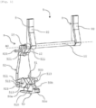
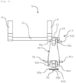
- the set 5 shown on the Figures 1 to 8 comprises a pair of arms 8 movable between a raised position and a lowered position, a pivoting actuating mechanism 9 for the arms 8 from the raised position to the lowered position and means 10 for returning the arms 8 to the raised position.
- the two movable arms 8 are configured and arranged so as to be in the plane of the lateral beam 31 in the raised position ( Figures 4 And 7 ) and to come into contact with the projectile 2 in order to press it against the bottom of the stretcher 3 in the lowered position ( Figure 5 ).
- the two arms 8 are spaced apart from each other along the lateral spar 31, in other words in the longitudinal direction of the stretcher 3, and extend parallel to each other and in longitudinal alignment with each other.
- Each arm 8 has a concave longitudinal profile and an opposite convex longitudinal profile. The concave longitudinal profile is directed towards the inside of the stretcher 3 and its surface, called support surface 80, is intended to cooperate with the contour of the projectile 2.
- each arm 8 is free and the other longitudinal end of each arm 8 is secured to a common actuating rod 11.
- This actuating rod 11 is a cylindrical rod mounted to rotate about a pivot axis A0 perpendicular to the longitudinal axis of each arm 8 and, in use, parallel to the longitudinal axis X0 of the stretcher 3.
- the actuating rod 11 is a torsion bar.
- the actuating rod 11 the longitudinal axis of which is coaxial with the pivot axis A0, is received in corresponding bores provided in the upper flanges 70.
- the actuating rod 11 and therefore the arms 8 are mounted to be movable in rotation only around the pivot axis A0.
- the actuating rod 11 also carries, between one of the arms 8 and its rear end, the actuating member 12 of the pivoting actuating mechanism 9.
- the actuating member 12 is in the form of a tab having one end secured to the actuating rod 11, and therefore movable in rotation around the pivot axis A0, and one end connected to the copying connecting rod 52 of said mechanism 9.
- the preferred embodiment of the invention has been described using a pair of arms 8. It is however possible to provide a single arm or more than two arms, for example two pairs arranged at a distance from each other.
- the pivoting actuating mechanism 9 is mounted between the actuating rod 11 and the connecting rod 40. As can be seen more particularly in the Figures 1 to 3 , this mechanism 9 comprises, in addition to the actuating member 12, three other movable parts connected together in an articulated manner, namely a pusher 50, a rocker 51 and a copying connecting rod 52.
- the pusher 50 comprises a base part 50a, a connecting part 50b and a cooperation part 50c formed in one piece.
- the base part 50a is in the form of a plate, for example of square section, and is slidably received in a pair of complementary grooves formed in the lower flange 71.
- the pusher 50 is mounted to move in translation relative to the stretcher 3, along a sliding axis X1.
- This sliding axis X1 is orthogonal to the pivot axis A0 and is located in a plane parallel to the plane of the connecting rod 40.
- the connecting part 50b is carried by the base part 50a and extends from the latter and above the latter, substantially in its center.
- This connecting part 50b comprises a rectilinear slot 500 opening opposite the base part 50a and capable of receiving in a pivoting and sliding manner one of the axes of the rocker 51.
- the cooperation part 50c extends from the connecting part 50b and in the direction of the cam path carried by the connecting rod 40.
- This cooperation part 50c is in the form of a rod whose free end intended to cooperate with the cam path is cylindrical.
- the rocker 51 comprises three axes 510, 511, 512 each arranged at a respective vertex of a triangle, when seen from the side, of which the axis 510 is received in the slot 500 of the pusher 50, an axis 511 mounted to rotate in corresponding bores of the lower flange 71, and an axis 512 articulated to the copying rod 52.
- These three axes 510, 511, 512 are parallel to each other and parallel to the pivot axis A0 of the arms 8.
- the rocker 51 may have two legs 513 facing each other and arranged on either side of the connecting part 50b, these two legs 513 being connected by the axis 510 received in the pusher 50 and by the axis 511 received in the flange 71.
- the axis 512 articulated to the copying rod 52 consists here of two coaxial cylindrical pivots extending on either side of the two legs 513.
- the copying rod 52 connects the rocker 51 to the actuating member 12 via a pivot connection with an axis parallel to the pivot axis A0.
- the pivot connection between the copying rod 52 and the rocker 51 is here defined by the axis 512, namely the two coaxial cylindrical pivots which pass through the two lugs 513 of the rocker 51 and two corresponding lugs 523 at a lower end of the copying rod 52.
- the pivot connection between the copying rod 52 and the actuating member 12 is defined by an axis 520 arranged above the axis 512 and passing through the actuating member 12 and two corresponding lugs 521 at the upper end of the copying rod 52.
- the return means 10 of the arms 8 in the raised position are formed by a return spring, in particular a spiral-type torsion spring mounted around the actuating rod 11, one end of the spring being integral with the actuating rod 11 while the other end is integral with an upper flange 70.
- a return spring in particular a spiral-type torsion spring mounted around the actuating rod 11, one end of the spring being integral with the actuating rod 11 while the other end is integral with an upper flange 70.
- a return spring is shown schematically in the Figures 1 And 2 .
- the recall means 10 are arranged and configured so as to to cause the actuating rod 11 to rotate around the pivot axis A0 in the absence of resistance at the pusher 50, resistance provided by the connecting rod 40.
- the return means 10 allow a rotation of the actuating rod 11 corresponding to an angular displacement of approximately 90 degrees of the pair of arms 8.
- the arms 8 pass from a lowered, substantially horizontal position to a raised, substantially vertical position. In the raised position,
Landscapes
- Engineering & Computer Science (AREA)
- General Engineering & Computer Science (AREA)
- Radiation-Therapy Devices (AREA)
- Furnace Charging Or Discharging (AREA)
- Aiming, Guidance, Guns With A Light Source, Armor, Camouflage, And Targets (AREA)
- Automatic Assembly (AREA)
- Accommodation For Nursing Or Treatment Tables (AREA)
- Toys (AREA)
Applications Claiming Priority (1)
| Application Number | Priority Date | Filing Date | Title |
|---|---|---|---|
| FR2315191A FR3157926B1 (fr) | 2024-01-02 | 2024-01-02 | Ensemble de positionnement et de maintien en position d’un projectile dans une civière et dispositif d’aide au chargement comportant un tel ensemble |
Publications (1)
| Publication Number | Publication Date |
|---|---|
| EP4582764A1 true EP4582764A1 (fr) | 2025-07-09 |
Family
ID=91072866
Family Applications (1)
| Application Number | Title | Priority Date | Filing Date |
|---|---|---|---|
| EP24223256.9A Pending EP4582764A1 (fr) | 2024-01-02 | 2024-12-24 | Ensemble de positionnement et de maintien en position d'un projectile dans une civière et dispositif d'aide au chargement comportant un tel ensemble |
Country Status (6)
| Country | Link |
|---|---|
| US (1) | US12560393B2 (https=) |
| EP (1) | EP4582764A1 (https=) |
| JP (1) | JP2025114487A (https=) |
| KR (1) | KR20250106237A (https=) |
| FR (1) | FR3157926B1 (https=) |
| ZA (1) | ZA202409913B (https=) |
Families Citing this family (1)
| Publication number | Priority date | Publication date | Assignee | Title |
|---|---|---|---|---|
| FR3157926B1 (fr) * | 2024-01-02 | 2026-01-16 | Nexter Systems | Ensemble de positionnement et de maintien en position d’un projectile dans une civière et dispositif d’aide au chargement comportant un tel ensemble |
Citations (9)
| Publication number | Priority date | Publication date | Assignee | Title |
|---|---|---|---|---|
| GB1492815A (en) * | 1974-01-15 | 1977-11-23 | Bofors Ab | Ammunition handling system |
| EP0022286A1 (de) * | 1979-07-06 | 1981-01-14 | Werkzeugmaschinenfabrik Oerlikon-Bührle AG | Ladeautomat für ein Panzerfahrzeug |
| EP0058814A2 (en) * | 1981-02-19 | 1982-09-01 | Fmc Corporation | Vertical loading system for a gun mount |
| FR2721387A1 (fr) | 1994-06-16 | 1995-12-22 | Giat Ind Sa | Mécanisme de mise à poste d'une munition. |
| FR2796713A1 (fr) | 1999-07-22 | 2001-01-26 | Giat Ind Sa | Dispositif d'aide au chargement pour artillerie |
| FR3043190A1 (fr) | 2015-10-29 | 2017-05-05 | Nexter Systems | Refouloir a obus |
| FR3054656A1 (fr) * | 2016-08-01 | 2018-02-02 | Nexter Systems | Dispositif de blocage d'un obus et civiere comportant un tel dispositif de blocage |
| FR3114384A1 (fr) | 2020-09-18 | 2022-03-25 | Nexter Systems | Dispositif de chargement d'un obus dans la chambre d'une arme |
| DE102021117951A1 (de) * | 2021-07-12 | 2023-01-12 | Rheinmetall Air Defence Ag | Zuführvorrichtung zum Beladen und Entladen eines radial öffnenden Munitionsbechers für ein automatisches Ladesystem eines Geschützes |
Family Cites Families (3)
| Publication number | Priority date | Publication date | Assignee | Title |
|---|---|---|---|---|
| DE10029477A1 (de) * | 2000-06-15 | 2001-12-20 | Krauss Maffei Wegmann Gmbh & C | Einrichtung zur Zuführung von großkalibrigen Geschossen zu einer schweren Waffe, insbesondere einer Panzerhaubitze |
| FR3157528B1 (fr) * | 2023-12-26 | 2026-01-02 | Nexter Systems | Dispositif de récupération de culots et arme équipée d’un tel dispositif |
| FR3157926B1 (fr) * | 2024-01-02 | 2026-01-16 | Nexter Systems | Ensemble de positionnement et de maintien en position d’un projectile dans une civière et dispositif d’aide au chargement comportant un tel ensemble |
-
2024
- 2024-01-02 FR FR2315191A patent/FR3157926B1/fr active Active
- 2024-12-20 ZA ZA2024/09913A patent/ZA202409913B/en unknown
- 2024-12-24 EP EP24223256.9A patent/EP4582764A1/fr active Pending
- 2024-12-25 JP JP2024228171A patent/JP2025114487A/ja active Pending
- 2024-12-30 KR KR1020240200667A patent/KR20250106237A/ko active Pending
- 2024-12-31 US US19/006,502 patent/US12560393B2/en active Active
Patent Citations (9)
| Publication number | Priority date | Publication date | Assignee | Title |
|---|---|---|---|---|
| GB1492815A (en) * | 1974-01-15 | 1977-11-23 | Bofors Ab | Ammunition handling system |
| EP0022286A1 (de) * | 1979-07-06 | 1981-01-14 | Werkzeugmaschinenfabrik Oerlikon-Bührle AG | Ladeautomat für ein Panzerfahrzeug |
| EP0058814A2 (en) * | 1981-02-19 | 1982-09-01 | Fmc Corporation | Vertical loading system for a gun mount |
| FR2721387A1 (fr) | 1994-06-16 | 1995-12-22 | Giat Ind Sa | Mécanisme de mise à poste d'une munition. |
| FR2796713A1 (fr) | 1999-07-22 | 2001-01-26 | Giat Ind Sa | Dispositif d'aide au chargement pour artillerie |
| FR3043190A1 (fr) | 2015-10-29 | 2017-05-05 | Nexter Systems | Refouloir a obus |
| FR3054656A1 (fr) * | 2016-08-01 | 2018-02-02 | Nexter Systems | Dispositif de blocage d'un obus et civiere comportant un tel dispositif de blocage |
| FR3114384A1 (fr) | 2020-09-18 | 2022-03-25 | Nexter Systems | Dispositif de chargement d'un obus dans la chambre d'une arme |
| DE102021117951A1 (de) * | 2021-07-12 | 2023-01-12 | Rheinmetall Air Defence Ag | Zuführvorrichtung zum Beladen und Entladen eines radial öffnenden Munitionsbechers für ein automatisches Ladesystem eines Geschützes |
Also Published As
| Publication number | Publication date |
|---|---|
| ZA202409913B (en) | 2025-05-28 |
| JP2025114487A (ja) | 2025-08-05 |
| KR20250106237A (ko) | 2025-07-09 |
| FR3157926B1 (fr) | 2026-01-16 |
| US12560393B2 (en) | 2026-02-24 |
| FR3157926A1 (fr) | 2025-07-04 |
| US20250251205A1 (en) | 2025-08-07 |
Similar Documents
| Publication | Publication Date | Title |
|---|---|---|
| EP0424210A1 (fr) | Dispositif de fixation d'une chaussure sur une pédale de bicyclette ou d'engin analogue, pédale de bicyclette, cale et semelle de chaussure pour un tel dispositif | |
| CA2841680C (fr) | Dispositif de prehension amovible d'un recipient culinaire muni de moyens antiretour de deux bras | |
| EP4582764A1 (fr) | Ensemble de positionnement et de maintien en position d'un projectile dans une civière et dispositif d'aide au chargement comportant un tel ensemble | |
| FR2663889A1 (fr) | Dispositif d'articulation d'un dossier demontable de siege arriere de vehicule. | |
| EP3249343B1 (fr) | Module de maintien de canon d'arme a feu et dispositif de support modulaire pour arme a feu comprenant un tel module ainsi qu'un module de maintien de crosse | |
| EP1626893A1 (fr) | Dispositif de fixation en porte-a-faux d'une roue de velo sur un cadre avec un mecanisme de serrage rapide | |
| FR2673744A1 (fr) | Dispositif de guidage de pieces de monnaie. | |
| EP2253926B1 (fr) | Dispositif de séparation d'un ensemble de modules de charge propulsive | |
| EP0244323A1 (fr) | Dispositif de levage, notamment pour manutentionner et ouvrir des conteneurs comportant deux coquilles articulées | |
| EP0219385A2 (fr) | Corbeille à papier | |
| EP4579169A1 (fr) | Dispositif de récupération de culots et arme équipée d'un tel dispositif | |
| EP0428480B1 (fr) | Fixation de sécurité à plaque | |
| FR2730948A1 (fr) | Dispositif destine a se monter sur une unite d'entrainement pour visser des vis | |
| FR2648502A1 (fr) | Serrure antipanique et boitier pour une telle serrure | |
| EP0571265A1 (fr) | Système de chargement d'une munition dans une chambre pivotante | |
| EP1548170B1 (fr) | Porte de tambour rotatif, notamment pour machine à laver et/ou sécher le linge | |
| EP3335824B1 (fr) | Système pour extraire une électrode à souder | |
| EP1253840A1 (fr) | Dispositif destine a l'ouverture des coquillages bivalves tels que les huitres | |
| EP1715282B1 (fr) | Dispositif d'alimentation en munitions | |
| FR2555526A1 (fr) | Mecanisme de commande pour siege de vehicule | |
| FR2500879A1 (fr) | Fermeture a declic pour portes d'armoires ou elements analogues | |
| EP3333059B1 (fr) | Pédale automatique de vélo | |
| EP4249843A1 (fr) | Dispositif perfectionné de chargement d'un obus dans la chambre d'une arme | |
| FR2766536A1 (fr) | Systeme ralentisseur pour un ensemble comprenant deux organes mobiles | |
| WO2002053458A1 (fr) | Procede et dispositif pour amener et positionner des boites a un poste d'emboitage |
Legal Events
| Date | Code | Title | Description |
|---|---|---|---|
| PUAI | Public reference made under article 153(3) epc to a published international application that has entered the european phase |
Free format text: ORIGINAL CODE: 0009012 |
|
| STAA | Information on the status of an ep patent application or granted ep patent |
Free format text: STATUS: THE APPLICATION HAS BEEN PUBLISHED |
|
| AK | Designated contracting states |
Kind code of ref document: A1 Designated state(s): AL AT BE BG CH CY CZ DE DK EE ES FI FR GB GR HR HU IE IS IT LI LT LU LV MC ME MK MT NL NO PL PT RO RS SE SI SK SM TR |
|
| STAA | Information on the status of an ep patent application or granted ep patent |
Free format text: STATUS: REQUEST FOR EXAMINATION WAS MADE |
|
| 17P | Request for examination filed |
Effective date: 20260109 |