EP4582675A2 - Kondensator für eine mit wasserstoffdampf injizierte brennkraftmaschine - Google Patents
Kondensator für eine mit wasserstoffdampf injizierte brennkraftmaschine Download PDFInfo
- Publication number
- EP4582675A2 EP4582675A2 EP25170201.5A EP25170201A EP4582675A2 EP 4582675 A2 EP4582675 A2 EP 4582675A2 EP 25170201 A EP25170201 A EP 25170201A EP 4582675 A2 EP4582675 A2 EP 4582675A2
- Authority
- EP
- European Patent Office
- Prior art keywords
- water
- condenser
- gas flow
- passages
- high energy
- Prior art date
- Legal status (The legal status is an assumption and is not a legal conclusion. Google has not performed a legal analysis and makes no representation as to the accuracy of the status listed.)
- Pending
Links
Images


Classifications
-
- F—MECHANICAL ENGINEERING; LIGHTING; HEATING; WEAPONS; BLASTING
- F02—COMBUSTION ENGINES; HOT-GAS OR COMBUSTION-PRODUCT ENGINE PLANTS
- F02C—GAS-TURBINE PLANTS; AIR INTAKES FOR JET-PROPULSION PLANTS; CONTROLLING FUEL SUPPLY IN AIR-BREATHING JET-PROPULSION PLANTS
- F02C7/00—Features, components parts, details or accessories, not provided for in, or of interest apart form groups F02C1/00 - F02C6/00; Air intakes for jet-propulsion plants
- F02C7/12—Cooling of plants
- F02C7/14—Cooling of plants of fluids in the plant, e.g. lubricant or fuel
- F02C7/141—Cooling of plants of fluids in the plant, e.g. lubricant or fuel of working fluid
-
- F—MECHANICAL ENGINEERING; LIGHTING; HEATING; WEAPONS; BLASTING
- F02—COMBUSTION ENGINES; HOT-GAS OR COMBUSTION-PRODUCT ENGINE PLANTS
- F02K—JET-PROPULSION PLANTS
- F02K1/00—Plants characterised by the form or arrangement of the jet pipe or nozzle; Jet pipes or nozzles peculiar thereto
- F02K1/78—Other construction of jet pipes
- F02K1/82—Jet pipe walls, e.g. liners
- F02K1/822—Heat insulating structures or liners, cooling arrangements, e.g. post combustion liners; Infrared radiation suppressors
-
- B—PERFORMING OPERATIONS; TRANSPORTING
- B01—PHYSICAL OR CHEMICAL PROCESSES OR APPARATUS IN GENERAL
- B01D—SEPARATION
- B01D53/00—Separation of gases or vapours; Recovering vapours of volatile solvents from gases; Chemical or biological purification of waste gases, e.g. engine exhaust gases, smoke, fumes, flue gases, aerosols
- B01D53/26—Drying gases or vapours
- B01D53/265—Drying gases or vapours by refrigeration (condensation)
-
- F—MECHANICAL ENGINEERING; LIGHTING; HEATING; WEAPONS; BLASTING
- F01—MACHINES OR ENGINES IN GENERAL; ENGINE PLANTS IN GENERAL; STEAM ENGINES
- F01D—NON-POSITIVE DISPLACEMENT MACHINES OR ENGINES, e.g. STEAM TURBINES
- F01D25/00—Component parts, details, or accessories, not provided for in, or of interest apart from, other groups
- F01D25/08—Cooling; Heating; Heat-insulation
- F01D25/12—Cooling
-
- F—MECHANICAL ENGINEERING; LIGHTING; HEATING; WEAPONS; BLASTING
- F01—MACHINES OR ENGINES IN GENERAL; ENGINE PLANTS IN GENERAL; STEAM ENGINES
- F01D—NON-POSITIVE DISPLACEMENT MACHINES OR ENGINES, e.g. STEAM TURBINES
- F01D25/00—Component parts, details, or accessories, not provided for in, or of interest apart from, other groups
- F01D25/30—Exhaust heads, chambers, or the like
-
- F—MECHANICAL ENGINEERING; LIGHTING; HEATING; WEAPONS; BLASTING
- F01—MACHINES OR ENGINES IN GENERAL; ENGINE PLANTS IN GENERAL; STEAM ENGINES
- F01D—NON-POSITIVE DISPLACEMENT MACHINES OR ENGINES, e.g. STEAM TURBINES
- F01D25/00—Component parts, details, or accessories, not provided for in, or of interest apart from, other groups
- F01D25/32—Collecting of condensation water; Drainage ; Removing solid particles
-
- F—MECHANICAL ENGINEERING; LIGHTING; HEATING; WEAPONS; BLASTING
- F02—COMBUSTION ENGINES; HOT-GAS OR COMBUSTION-PRODUCT ENGINE PLANTS
- F02C—GAS-TURBINE PLANTS; AIR INTAKES FOR JET-PROPULSION PLANTS; CONTROLLING FUEL SUPPLY IN AIR-BREATHING JET-PROPULSION PLANTS
- F02C3/00—Gas-turbine plants characterised by the use of combustion products as the working fluid
- F02C3/20—Gas-turbine plants characterised by the use of combustion products as the working fluid using a special fuel, oxidant, or dilution fluid to generate the combustion products
- F02C3/22—Gas-turbine plants characterised by the use of combustion products as the working fluid using a special fuel, oxidant, or dilution fluid to generate the combustion products the fuel or oxidant being gaseous at standard temperature and pressure
-
- F—MECHANICAL ENGINEERING; LIGHTING; HEATING; WEAPONS; BLASTING
- F02—COMBUSTION ENGINES; HOT-GAS OR COMBUSTION-PRODUCT ENGINE PLANTS
- F02C—GAS-TURBINE PLANTS; AIR INTAKES FOR JET-PROPULSION PLANTS; CONTROLLING FUEL SUPPLY IN AIR-BREATHING JET-PROPULSION PLANTS
- F02C3/00—Gas-turbine plants characterised by the use of combustion products as the working fluid
- F02C3/20—Gas-turbine plants characterised by the use of combustion products as the working fluid using a special fuel, oxidant, or dilution fluid to generate the combustion products
- F02C3/30—Adding water, steam or other fluids for influencing combustion, e.g. to obtain cleaner exhaust gases
- F02C3/305—Increasing the power, speed, torque or efficiency of a gas turbine or the thrust of a turbojet engine by injecting or adding water, steam or other fluids
-
- B—PERFORMING OPERATIONS; TRANSPORTING
- B01—PHYSICAL OR CHEMICAL PROCESSES OR APPARATUS IN GENERAL
- B01D—SEPARATION
- B01D2258/00—Sources of waste gases
- B01D2258/01—Engine exhaust gases
-
- B—PERFORMING OPERATIONS; TRANSPORTING
- B01—PHYSICAL OR CHEMICAL PROCESSES OR APPARATUS IN GENERAL
- B01D—SEPARATION
- B01D2259/00—Type of treatment
- B01D2259/45—Gas separation or purification devices adapted for specific applications
- B01D2259/4566—Gas separation or purification devices adapted for specific applications for use in transportation means
- B01D2259/4575—Gas separation or purification devices adapted for specific applications for use in transportation means in aeroplanes or space ships
-
- F—MECHANICAL ENGINEERING; LIGHTING; HEATING; WEAPONS; BLASTING
- F05—INDEXING SCHEMES RELATING TO ENGINES OR PUMPS IN VARIOUS SUBCLASSES OF CLASSES F01-F04
- F05D—INDEXING SCHEME FOR ASPECTS RELATING TO NON-POSITIVE-DISPLACEMENT MACHINES OR ENGINES, GAS-TURBINES OR JET-PROPULSION PLANTS
- F05D2220/00—Application
- F05D2220/30—Application in turbines
- F05D2220/32—Application in turbines in gas turbines
- F05D2220/323—Application in turbines in gas turbines for aircraft propulsion, e.g. jet engines
-
- F—MECHANICAL ENGINEERING; LIGHTING; HEATING; WEAPONS; BLASTING
- F05—INDEXING SCHEMES RELATING TO ENGINES OR PUMPS IN VARIOUS SUBCLASSES OF CLASSES F01-F04
- F05D—INDEXING SCHEME FOR ASPECTS RELATING TO NON-POSITIVE-DISPLACEMENT MACHINES OR ENGINES, GAS-TURBINES OR JET-PROPULSION PLANTS
- F05D2220/00—Application
- F05D2220/60—Application making use of surplus or waste energy
-
- F—MECHANICAL ENGINEERING; LIGHTING; HEATING; WEAPONS; BLASTING
- F05—INDEXING SCHEMES RELATING TO ENGINES OR PUMPS IN VARIOUS SUBCLASSES OF CLASSES F01-F04
- F05D—INDEXING SCHEME FOR ASPECTS RELATING TO NON-POSITIVE-DISPLACEMENT MACHINES OR ENGINES, GAS-TURBINES OR JET-PROPULSION PLANTS
- F05D2260/00—Function
- F05D2260/20—Heat transfer, e.g. cooling
- F05D2260/213—Heat transfer, e.g. cooling by the provision of a heat exchanger within the cooling circuit
-
- F—MECHANICAL ENGINEERING; LIGHTING; HEATING; WEAPONS; BLASTING
- F05—INDEXING SCHEMES RELATING TO ENGINES OR PUMPS IN VARIOUS SUBCLASSES OF CLASSES F01-F04
- F05D—INDEXING SCHEME FOR ASPECTS RELATING TO NON-POSITIVE-DISPLACEMENT MACHINES OR ENGINES, GAS-TURBINES OR JET-PROPULSION PLANTS
- F05D2260/00—Function
- F05D2260/20—Heat transfer, e.g. cooling
- F05D2260/221—Improvement of heat transfer
- F05D2260/2214—Improvement of heat transfer by increasing the heat transfer surface
-
- F—MECHANICAL ENGINEERING; LIGHTING; HEATING; WEAPONS; BLASTING
- F05—INDEXING SCHEMES RELATING TO ENGINES OR PUMPS IN VARIOUS SUBCLASSES OF CLASSES F01-F04
- F05D—INDEXING SCHEME FOR ASPECTS RELATING TO NON-POSITIVE-DISPLACEMENT MACHINES OR ENGINES, GAS-TURBINES OR JET-PROPULSION PLANTS
- F05D2260/00—Function
- F05D2260/60—Fluid transfer
Definitions
- the present invention relates generally to a hydrogen powered aircraft propulsion system and, more particularly to hydrogen steam injected and intercooled turbine engine.
- Turbine engine manufacturers continue to seek further improvements to engine performance including improvements to reduce environmental impact while improving propulsive efficiencies.
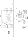
- a propulsion system for an aircraft includes a core engine that includes a core flow path where air is compressed in a compressor section, communicated to a combustor section, mixed with a hydrogen based fuel and ignited to generate a high energy gas flow that is expanded through a turbine section.
- a hydrogen fuel system is configured to supply hydrogen fuel to the combustor through a fuel flow path.
- a condenser is arranged along the core flow path and is configured to extract water from the high energy gas flow. The condenser includes a plurality of rotating passages that are disposed in a collector.
- the passages are configured to rotate about a condenser axis to generate a transverse pressure gradient to direct water out of the high energy gas flow toward the collector.
- An evaporator is arranged along the core flow path and is configured to receive a portion of the water that is extracted by the condenser to generate a steam flow. The steam flow is injected into the core flow path upstream of the turbine section.
- the condenser is configured to receive a cooling flow to cool the high energy gas flow.
- the condenser is configured to receive the cooling flow at a location along an outer periphery.
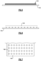
- the plurality of rotating passages include a plurality of spiral layers that extend axially about a condenser axis.
- the plurality of spiral layers include openings that are configured to exhaust water that is collected from the high energy gas flow to the collector.
- the condenser includes a plurality of axial passages and a plurality of transition passages for directing the high energy gas flow into the rotating passages.
- the propulsion system includes a shaft that is disposed along the condenser axis for supporting rotation of the rotating passages.
- the propulsion system includes a motor that is coupled to the shaft and is configured to drive rotation of the rotating passages.
- the plurality of rotating passages is configured to rotate about the shaft in response to an axial momentum of the high energy gas flow.
- the plurality of rotating passages include a hydrophilic coating.
Landscapes
- Engineering & Computer Science (AREA)
- Chemical & Material Sciences (AREA)
- Mechanical Engineering (AREA)
- General Engineering & Computer Science (AREA)
- Combustion & Propulsion (AREA)
- Thermal Sciences (AREA)
- Physics & Mathematics (AREA)
- Analytical Chemistry (AREA)
- General Chemical & Material Sciences (AREA)
- Oil, Petroleum & Natural Gas (AREA)
- Chemical Kinetics & Catalysis (AREA)
- Engine Equipment That Uses Special Cycles (AREA)
- Hydrogen, Water And Hydrids (AREA)
Applications Claiming Priority (2)
| Application Number | Priority Date | Filing Date | Title |
|---|---|---|---|
| US17/744,379 US11920515B2 (en) | 2022-05-13 | 2022-05-13 | Condenser for hydrogen steam injected turbine engine |
| EP23173237.1A EP4276291B1 (de) | 2022-05-13 | 2023-05-12 | Kondensator für wasserstoffdampfeinspritzturbinenmotor |
Related Parent Applications (1)
| Application Number | Title | Priority Date | Filing Date |
|---|---|---|---|
| EP23173237.1A Division EP4276291B1 (de) | 2022-05-13 | 2023-05-12 | Kondensator für wasserstoffdampfeinspritzturbinenmotor |
Publications (2)
| Publication Number | Publication Date |
|---|---|
| EP4582675A2 true EP4582675A2 (de) | 2025-07-09 |
| EP4582675A3 EP4582675A3 (de) | 2025-08-06 |
Family
ID=86378338
Family Applications (2)
| Application Number | Title | Priority Date | Filing Date |
|---|---|---|---|
| EP23173237.1A Active EP4276291B1 (de) | 2022-05-13 | 2023-05-12 | Kondensator für wasserstoffdampfeinspritzturbinenmotor |
| EP25170201.5A Pending EP4582675A3 (de) | 2022-05-13 | 2023-05-12 | Kondensator für eine mit wasserstoffdampf injizierte brennkraftmaschine |
Family Applications Before (1)
| Application Number | Title | Priority Date | Filing Date |
|---|---|---|---|
| EP23173237.1A Active EP4276291B1 (de) | 2022-05-13 | 2023-05-12 | Kondensator für wasserstoffdampfeinspritzturbinenmotor |
Country Status (2)
| Country | Link |
|---|---|
| US (1) | US11920515B2 (de) |
| EP (2) | EP4276291B1 (de) |
Families Citing this family (6)
| Publication number | Priority date | Publication date | Assignee | Title |
|---|---|---|---|---|
| US12523176B2 (en) | 2022-06-22 | 2026-01-13 | General Electric Company | Gearbox assembly with lubricant extraction volume ratio |
| EP4390088A1 (de) * | 2022-12-21 | 2024-06-26 | MTU Aero Engines AG | Verfahren zum betreiben einer strömungsmaschine für einen flugantrieb |
| US12031485B1 (en) * | 2023-04-21 | 2024-07-09 | Rtx Corporation | Water storage precooling and water cycle chiller |
| US12012892B1 (en) * | 2023-05-19 | 2024-06-18 | Rtx Corporation | Water separator for turbine engine |
| US12221905B1 (en) * | 2023-08-07 | 2025-02-11 | General Electric Company | Turbine engine including a steam system |
| US20250369393A1 (en) * | 2024-05-30 | 2025-12-04 | Rtx Corporation | Axial flow angled condenser arrangement for an aircraft propulsion system |
Family Cites Families (8)
| Publication number | Priority date | Publication date | Assignee | Title |
|---|---|---|---|---|
| US3657879A (en) * | 1970-01-26 | 1972-04-25 | Walter J Ewbank | Gas-steam engine |
| US4248039A (en) * | 1978-12-06 | 1981-02-03 | International Power Technology, Inc. | Regenerative parallel compound dual fluid heat engine |
| US10247408B2 (en) * | 2014-11-14 | 2019-04-02 | University Of Florida Research Foundation, Inc. | Humid air turbine power, water extraction, and refrigeration cycle |
| GB201501045D0 (en) | 2015-01-22 | 2015-03-11 | Rolls Royce Plc | Aircraft propulsion system |
| GB2531632B (en) | 2015-08-10 | 2017-01-11 | Latif Qureshi Masood | A mechanical device to suppress contrail formation |
| DE102018203159B4 (de) | 2018-03-02 | 2021-05-06 | MTU Aero Engines AG | Reduktion von Kondensstreifen beim Betrieb von Fluggeräten |
| DE102018208026A1 (de) * | 2018-05-22 | 2019-11-28 | MTU Aero Engines AG | Abgasbehandlungsvorrichtung, Flugzeugantriebssystem und Verfahren zum Behandeln eines Abgasstromes |
| GB202114829D0 (en) * | 2021-10-18 | 2021-12-01 | Rolls Royce Plc | Aircraft propulsion system |
-
2022
- 2022-05-13 US US17/744,379 patent/US11920515B2/en active Active
-
2023
- 2023-05-12 EP EP23173237.1A patent/EP4276291B1/de active Active
- 2023-05-12 EP EP25170201.5A patent/EP4582675A3/de active Pending
Also Published As
| Publication number | Publication date |
|---|---|
| EP4276291A1 (de) | 2023-11-15 |
| US20230366351A1 (en) | 2023-11-16 |
| US11920515B2 (en) | 2024-03-05 |
| EP4276291B1 (de) | 2025-04-16 |
| EP4582675A3 (de) | 2025-08-06 |
Similar Documents
| Publication | Publication Date | Title |
|---|---|---|
| EP4582675A2 (de) | Kondensator für eine mit wasserstoffdampf injizierte brennkraftmaschine | |
| EP4276292B1 (de) | Antriebssystem für ein flugzeug | |
| EP4279722B1 (de) | Wasserabscheider für wasserstoffgetriebenen turbinenmotor | |
| EP4279720B1 (de) | Turbinenmotor mit überhitzter dampfeinspritzung | |
| EP4321744B1 (de) | Zwischengekühlte vorwärmung eines dampfeinspritzenden turbinenmotors | |
| EP4279718A1 (de) | Wasserstoffbetriebener kondensatorkanal eines turbinenmotors | |
| EP4407162A1 (de) | Wasserstoffdampfeinspritzturbinenmotor mit turboexpanderwärmerückgewinnung | |
| EP4279723A1 (de) | Wasserstoffturbinenmotor mit dampfeinspritzung und zwischenkühlung | |
| EP4411122A2 (de) | Ein antriebssystem für ein flugzeug | |
| EP4414542A1 (de) | Wasserabscheider für wasserstoffdampfeinspritzturbinenmotor | |
| EP4407160A1 (de) | Abwärmerückgewinnung aus leistungselektronik in einem rückgewinnungszyklus | |
| EP4279719B1 (de) | Wasserstoffdampfeinspritzturbinenmotor mit gekühlter kühlluft | |
| EP4279721B1 (de) | Wasserstoffdampfeinspritzturbinenmotor mit rückströmung | |
| EP4722516A2 (de) | Versetzter kern mit seitenausstossgondeldüsen | |
| US20250250932A1 (en) | Turbine Engine Including a Condenser System | |
| EP4517069A1 (de) | Teilabsaugung und bodenkreislauf | |
| EP4656860A1 (de) | Konische kondensatoranordnung mit axialer strömung für ein flugzeugantriebssystem |
Legal Events
| Date | Code | Title | Description |
|---|---|---|---|
| PUAI | Public reference made under article 153(3) epc to a published international application that has entered the european phase |
Free format text: ORIGINAL CODE: 0009012 |
|
| STAA | Information on the status of an ep patent application or granted ep patent |
Free format text: STATUS: THE APPLICATION HAS BEEN PUBLISHED |
|
| REG | Reference to a national code |
Ref country code: DE Ref legal event code: R079 Free format text: PREVIOUS MAIN CLASS: F01D0025120000 Ipc: F02C0003220000 |
|
| PUAL | Search report despatched |
Free format text: ORIGINAL CODE: 0009013 |
|
| AC | Divisional application: reference to earlier application |
Ref document number: 4276291 Country of ref document: EP Kind code of ref document: P |
|
| AK | Designated contracting states |
Kind code of ref document: A2 Designated state(s): AL AT BE BG CH CY CZ DE DK EE ES FI FR GB GR HR HU IE IS IT LI LT LU LV MC ME MK MT NL NO PL PT RO RS SE SI SK SM TR |
|
| AK | Designated contracting states |
Kind code of ref document: A3 Designated state(s): AL AT BE BG CH CY CZ DE DK EE ES FI FR GB GR HR HU IE IS IT LI LT LU LV MC ME MK MT NL NO PL PT RO RS SE SI SK SM TR |
|
| RIC1 | Information provided on ipc code assigned before grant |
Ipc: F02C 3/22 20060101AFI20250627BHEP Ipc: B01D 53/24 20060101ALI20250627BHEP Ipc: B01D 53/26 20060101ALI20250627BHEP Ipc: F01D 25/30 20060101ALI20250627BHEP Ipc: F01D 25/32 20060101ALI20250627BHEP Ipc: F02C 3/30 20060101ALI20250627BHEP Ipc: F02K 1/82 20060101ALI20250627BHEP |
|
| STAA | Information on the status of an ep patent application or granted ep patent |
Free format text: STATUS: REQUEST FOR EXAMINATION WAS MADE |
|
| 17P | Request for examination filed |
Effective date: 20260206 |