EP4407160A1 - Abwärmerückgewinnung aus leistungselektronik in einem rückgewinnungszyklus - Google Patents
Abwärmerückgewinnung aus leistungselektronik in einem rückgewinnungszyklus Download PDFInfo
- Publication number
- EP4407160A1 EP4407160A1 EP23211847.1A EP23211847A EP4407160A1 EP 4407160 A1 EP4407160 A1 EP 4407160A1 EP 23211847 A EP23211847 A EP 23211847A EP 4407160 A1 EP4407160 A1 EP 4407160A1
- Authority
- EP
- European Patent Office
- Prior art keywords
- propulsion system
- flow
- fuel
- recited
- electrical device
- Prior art date
- Legal status (The legal status is an assumption and is not a legal conclusion. Google has not performed a legal analysis and makes no representation as to the accuracy of the status listed.)
- Pending
Links
Images
Classifications
-
- F—MECHANICAL ENGINEERING; LIGHTING; HEATING; WEAPONS; BLASTING
- F01—MACHINES OR ENGINES IN GENERAL; ENGINE PLANTS IN GENERAL; STEAM ENGINES
- F01K—STEAM ENGINE PLANTS; STEAM ACCUMULATORS; ENGINE PLANTS NOT OTHERWISE PROVIDED FOR; ENGINES USING SPECIAL WORKING FLUIDS OR CYCLES
- F01K15/00—Adaptations of plants for special use
- F01K15/02—Adaptations of plants for special use for driving vehicles, e.g. locomotives
-
- F—MECHANICAL ENGINEERING; LIGHTING; HEATING; WEAPONS; BLASTING
- F02—COMBUSTION ENGINES; HOT-GAS OR COMBUSTION-PRODUCT ENGINE PLANTS
- F02C—GAS-TURBINE PLANTS; AIR INTAKES FOR JET-PROPULSION PLANTS; CONTROLLING FUEL SUPPLY IN AIR-BREATHING JET-PROPULSION PLANTS
- F02C3/00—Gas-turbine plants characterised by the use of combustion products as the working fluid
- F02C3/20—Gas-turbine plants characterised by the use of combustion products as the working fluid using a special fuel, oxidant, or dilution fluid to generate the combustion products
- F02C3/22—Gas-turbine plants characterised by the use of combustion products as the working fluid using a special fuel, oxidant, or dilution fluid to generate the combustion products the fuel or oxidant being gaseous at standard temperature and pressure
-
- B—PERFORMING OPERATIONS; TRANSPORTING
- B64—AIRCRAFT; AVIATION; COSMONAUTICS
- B64D—EQUIPMENT FOR FITTING IN OR TO AIRCRAFT; FLIGHT SUITS; PARACHUTES; ARRANGEMENT OR MOUNTING OF POWER PLANTS OR PROPULSION TRANSMISSIONS IN AIRCRAFT
- B64D27/00—Arrangement or mounting of power plants in aircraft; Aircraft characterised by the type or position of power plants
- B64D27/02—Aircraft characterised by the type or position of power plants
- B64D27/10—Aircraft characterised by the type or position of power plants of gas-turbine type
-
- B—PERFORMING OPERATIONS; TRANSPORTING
- B64—AIRCRAFT; AVIATION; COSMONAUTICS
- B64D—EQUIPMENT FOR FITTING IN OR TO AIRCRAFT; FLIGHT SUITS; PARACHUTES; ARRANGEMENT OR MOUNTING OF POWER PLANTS OR PROPULSION TRANSMISSIONS IN AIRCRAFT
- B64D27/00—Arrangement or mounting of power plants in aircraft; Aircraft characterised by the type or position of power plants
- B64D27/02—Aircraft characterised by the type or position of power plants
- B64D27/24—Aircraft characterised by the type or position of power plants using steam or spring force
-
- B—PERFORMING OPERATIONS; TRANSPORTING
- B64—AIRCRAFT; AVIATION; COSMONAUTICS
- B64D—EQUIPMENT FOR FITTING IN OR TO AIRCRAFT; FLIGHT SUITS; PARACHUTES; ARRANGEMENT OR MOUNTING OF POWER PLANTS OR PROPULSION TRANSMISSIONS IN AIRCRAFT
- B64D33/00—Arrangement in aircraft of power plant parts or auxiliaries not otherwise provided for
- B64D33/08—Arrangement in aircraft of power plant parts or auxiliaries not otherwise provided for of power plant cooling systems
-
- F—MECHANICAL ENGINEERING; LIGHTING; HEATING; WEAPONS; BLASTING
- F01—MACHINES OR ENGINES IN GENERAL; ENGINE PLANTS IN GENERAL; STEAM ENGINES
- F01K—STEAM ENGINE PLANTS; STEAM ACCUMULATORS; ENGINE PLANTS NOT OTHERWISE PROVIDED FOR; ENGINES USING SPECIAL WORKING FLUIDS OR CYCLES
- F01K17/00—Using steam or condensate extracted or exhausted from steam engine plant
- F01K17/04—Using steam or condensate extracted or exhausted from steam engine plant for specific purposes other than heating
-
- F—MECHANICAL ENGINEERING; LIGHTING; HEATING; WEAPONS; BLASTING
- F01—MACHINES OR ENGINES IN GENERAL; ENGINE PLANTS IN GENERAL; STEAM ENGINES
- F01K—STEAM ENGINE PLANTS; STEAM ACCUMULATORS; ENGINE PLANTS NOT OTHERWISE PROVIDED FOR; ENGINES USING SPECIAL WORKING FLUIDS OR CYCLES
- F01K27/00—Plants for converting heat or fluid energy into mechanical energy, not otherwise provided for
- F01K27/02—Plants modified to use their waste heat, other than that of exhaust, e.g. engine-friction heat
-
- F—MECHANICAL ENGINEERING; LIGHTING; HEATING; WEAPONS; BLASTING
- F02—COMBUSTION ENGINES; HOT-GAS OR COMBUSTION-PRODUCT ENGINE PLANTS
- F02C—GAS-TURBINE PLANTS; AIR INTAKES FOR JET-PROPULSION PLANTS; CONTROLLING FUEL SUPPLY IN AIR-BREATHING JET-PROPULSION PLANTS
- F02C3/00—Gas-turbine plants characterised by the use of combustion products as the working fluid
- F02C3/20—Gas-turbine plants characterised by the use of combustion products as the working fluid using a special fuel, oxidant, or dilution fluid to generate the combustion products
- F02C3/30—Adding water, steam or other fluids for influencing combustion, e.g. to obtain cleaner exhaust gases
- F02C3/305—Increasing the power, speed, torque or efficiency of a gas turbine or the thrust of a turbojet engine by injecting or adding water, steam or other fluids
-
- F—MECHANICAL ENGINEERING; LIGHTING; HEATING; WEAPONS; BLASTING
- F02—COMBUSTION ENGINES; HOT-GAS OR COMBUSTION-PRODUCT ENGINE PLANTS
- F02C—GAS-TURBINE PLANTS; AIR INTAKES FOR JET-PROPULSION PLANTS; CONTROLLING FUEL SUPPLY IN AIR-BREATHING JET-PROPULSION PLANTS
- F02C7/00—Features, components parts, details or accessories, not provided for in, or of interest apart form groups F02C1/00 - F02C6/00; Air intakes for jet-propulsion plants
- F02C7/12—Cooling of plants
- F02C7/16—Cooling of plants characterised by cooling medium
-
- F—MECHANICAL ENGINEERING; LIGHTING; HEATING; WEAPONS; BLASTING
- F02—COMBUSTION ENGINES; HOT-GAS OR COMBUSTION-PRODUCT ENGINE PLANTS
- F02C—GAS-TURBINE PLANTS; AIR INTAKES FOR JET-PROPULSION PLANTS; CONTROLLING FUEL SUPPLY IN AIR-BREATHING JET-PROPULSION PLANTS
- F02C7/00—Features, components parts, details or accessories, not provided for in, or of interest apart form groups F02C1/00 - F02C6/00; Air intakes for jet-propulsion plants
- F02C7/22—Fuel supply systems
- F02C7/224—Heating fuel before feeding to the burner
-
- F—MECHANICAL ENGINEERING; LIGHTING; HEATING; WEAPONS; BLASTING
- F02—COMBUSTION ENGINES; HOT-GAS OR COMBUSTION-PRODUCT ENGINE PLANTS
- F02C—GAS-TURBINE PLANTS; AIR INTAKES FOR JET-PROPULSION PLANTS; CONTROLLING FUEL SUPPLY IN AIR-BREATHING JET-PROPULSION PLANTS
- F02C7/00—Features, components parts, details or accessories, not provided for in, or of interest apart form groups F02C1/00 - F02C6/00; Air intakes for jet-propulsion plants
- F02C7/32—Arrangement, mounting, or driving, of auxiliaries
-
- B—PERFORMING OPERATIONS; TRANSPORTING
- B64—AIRCRAFT; AVIATION; COSMONAUTICS
- B64D—EQUIPMENT FOR FITTING IN OR TO AIRCRAFT; FLIGHT SUITS; PARACHUTES; ARRANGEMENT OR MOUNTING OF POWER PLANTS OR PROPULSION TRANSMISSIONS IN AIRCRAFT
- B64D27/00—Arrangement or mounting of power plants in aircraft; Aircraft characterised by the type or position of power plants
- B64D27/02—Aircraft characterised by the type or position of power plants
- B64D27/026—Aircraft characterised by the type or position of power plants comprising different types of power plants, e.g. combination of a piston engine and a gas-turbine
-
- F—MECHANICAL ENGINEERING; LIGHTING; HEATING; WEAPONS; BLASTING
- F05—INDEXING SCHEMES RELATING TO ENGINES OR PUMPS IN VARIOUS SUBCLASSES OF CLASSES F01-F04
- F05D—INDEXING SCHEME FOR ASPECTS RELATING TO NON-POSITIVE-DISPLACEMENT MACHINES OR ENGINES, GAS-TURBINES OR JET-PROPULSION PLANTS
- F05D2220/00—Application
- F05D2220/70—Application in combination with
- F05D2220/76—Application in combination with an electrical generator
-
- F—MECHANICAL ENGINEERING; LIGHTING; HEATING; WEAPONS; BLASTING
- F05—INDEXING SCHEMES RELATING TO ENGINES OR PUMPS IN VARIOUS SUBCLASSES OF CLASSES F01-F04
- F05D—INDEXING SCHEME FOR ASPECTS RELATING TO NON-POSITIVE-DISPLACEMENT MACHINES OR ENGINES, GAS-TURBINES OR JET-PROPULSION PLANTS
- F05D2260/00—Function
- F05D2260/20—Heat transfer, e.g. cooling
- F05D2260/213—Heat transfer, e.g. cooling by the provision of a heat exchanger within the cooling circuit
Definitions
- the present disclosure relates generally to an alternate fuel turbine engine that includes a steam injection system that transforms water recovered from an exhaust gas flow into steam.
- Turbine engine manufacturers continue to seek further improvements to engine performance including improvements to reduce environmental impact while improving propulsive efficiencies.
- a propulsion system for an aircraft includes a core engine that includes a core flow path where air is compressed in a compressor section, communicated to a combustor section, mixed with a cryogenic fuel (such as a hydrogen based fuel, for example, liquid hydrogen (LH 2 )) and ignited to generate an exhaust gas flow that is expanded through a turbine section.
- a cryogenic fuel such as a hydrogen based fuel, for example, liquid hydrogen (LH 2 )
- the propulsion system includes a condenser that is arranged along the core flow path and configured to extract water from the exhaust gas flow, an evaporator that is arranged along the core flow path and configured to receive a portion of the water that is extracted by the condenser to generate a steam flow, the steam flow is injected into the core flow path upstream of the turbine section, an electrical device that generates thermal energy, and a heat exchanger where thermal energy from the electrical device is communicated to a cooling water flow.
- a flow of water is heated by thermal energy from the power electronic device in the heat exchanger is routed to the evaporator.
- the propulsion system further includes a sealed coolant circuit that includes a cooling circuit heat exchanger where a cooling medium transfers thermal energy from the electrical device to the cooling water flow.
- the electrical device includes an electric motor/generator.
- the electric motor/generator is coupled to drive at least one accessory device.
- the electrical device includes a power electronic device.
- the electrical device includes a fuel cell that generates electric power.
- the cryogenic fuel includes a hydrogen based fuel that is communicated to the fuel cell along with a bypass airflow.
- unused hydrogen based fuel expelled from the fuel cell is communicated back to a fuel storage tank.
- the turbine section includes at least a low pressure turbine, a high pressure turbine and an intermediate pressure turbine and the compressor section includes a high pressure compressor that is coupled to the high pressure turbine through a high shaft and a low pressure compressor is coupled to the intermediate pressure turbine through an intermediate shaft.
- the propulsion system includes a gearbox that is coupled to the low pressure turbine through a low shaft for driving a fan at a rotational speed lower than a rotational speed of the low pressure turbine.
- a propulsion system for an aircraft includes a core engine that includes a core flow path where air is compressed in a compressor section, communicated to a combustor section, mixed with a cryogenic fuel (such as a hydrogen based fuel, for example, liquid hydrogen (LH 2 )) and ignited to generate an exhaust gas flow that is expanded through a turbine section.
- a cryogenic fuel such as a hydrogen based fuel, for example, liquid hydrogen (LH 2 )
- the propulsion system includes a cryogenic fuel system for supplying the cryogenic fuel to the combustor through a fuel flow path
- the cryogenic fuel system includes a cryogenic fuel tank and a fuel pump for pressurizing a liquid cryogenic fuel
- a condenser is arranged along the core flow path and configured to extract water from the exhaust gas flow
- an evaporator is arranged along the core flow path and configured to receive a portion of the water that is extracted by the condenser to generate a steam flow
- the steam flow is injected into the core flow path upstream of the turbine section
- an electrical device generates thermal energy
- a heat exchanger is in thermal communication with the electrical device where thermal energy from the electrical device is communicated into a water flow.
- the condenser is in thermal communication with a bypass airflow passage for cooling the exhaust gas flow in the condenser during aircraft operation.
- the propulsion system further includes a sealed coolant circuit that includes a cooling circuit heat exchanger where a cooling medium transfers thermal energy from the electrical device to the cooling water flow.
- the electrical device includes an electric motor/generator.
- the electrical device includes a power electronic device.
- the electrical device includes a fuel cell that generates electric power.
- a method of recovering thermal energy from an electrical device in an aircraft propulsion system includes configuring a core engine to generate an exhaust gas flow from a cryogenic fuel (such as a hydrogen based fuel, for example, liquid hydrogen (LH 2 )), configuring a condenser to extract water from the exhaust gas flow, configuring an evaporator to generate a steam flow by heating extracted water from the condenser with a portion of the exhaust gas flow, and communicating thermal energy that is generated by an electrical device into a cooling water flow from the condenser within a heat exchanger.
- a cryogenic fuel such as a hydrogen based fuel, for example, liquid hydrogen (LH 2 )
- the method further includes communicating thermal energy that is generated by the electrical device into a cooling medium that circulates in a sealed cooling circuit and transfers thermal energy from the cooling medium into the cooling water flow.
- the electrical device includes one or more of an electric machine, power electronics or a fuel cell.
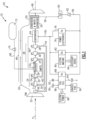
- Figure 1 schematically illustrates an example hydrogen steam injected inter-cooled turbine engine that is generally indicated at 20.
- the disclosed example engine embodiment utilizes a water is recovered from an exhaust gas flow to cool electrical devices and recover thermal energy to increase engine efficiency.
- the engine 20 includes core engine with a core airflow path C through a fan 22, a compressor section 24, a combustor 26 and a turbine section 28.
- the fan 22 drives inlet air as a core flow 54 into the compressor section 24.
- the core flow 54 is compressed and communicated to a combustor 26.
- the core flow 54 is mixed with a fuel flow 90 and ignited to generate a high energy gas flow 52 that expands through the turbine section 28 where energy is extracted and utilized to drive the fan 22 and the compressor section 24.
- a bypass flow 50 may flow through the fan 22 and bypass passage 48 that is disposed outside of the core engine to bypass the remaining components of the engine 20.
- the high energy gas flow 52 is exhausted from the turbine section 28 and communicated through an evaporator 64 and a condenser assembly 56 before being exhausted through a nozzle 68.
- the example compressor section 24 includes a low pressure compressor (LPC) 30 and a high pressure compressor (HPC) 32.
- the turbine section 28 includes a high pressure turbine (HPT) 34, an intermediate pressure turbine (IPT) 36, and a low pressure turbine (LPT) 38.
- the turbines 34, 36 and 38 are coupled to a corresponding compressor section.
- the HPT 34 is coupled by a high shaft 40 to drive the HPT 32.
- An intermediate shaft 42 couples the IPT 36 to the LPC 30.
- a low shaft 44 is coupled between the LPT 38 and a gearbox 46 to drive the fan 22.
- the example gearbox 46 is an epicyclical gear train, such as a planetary gear system, star gear system or other known gear system, with a gear reduction ratio of greater than about 2.3.
- the engine 20 is configured to burn hydrogen provided by a fuel system 70.
- the fuel system 70 includes a liquid hydrogen (LH 2 ) tank 72 in communication with at least one pump 74.
- the pump 74 drives a fuel flow 90 to the combustor through a fuel system and eventually to the combustor 26.
- the condenser 56 recovers water from the exhaust gas flow 52 and initially communicates that water 58 to a storage tank 60.
- the storage tank 60 operates as an accumulator to store water and accommodate fluctuations in engine operation and water recovery.
- a pump 62 pressurizes the water flow 58 and eventually communicates the water flow 58 to the evaporator 64.
- the evaporator 64 is exposed to heat from the exhaust gas flow 52 to generate a steam flow 66 from the water flow 58 from the condenser assembly 56.
- the generated steam improves performance by increasing turbine mass flow and power output without additional work required by the compressor section 24.
- the steam flow is injected into the combustor 26.
- the steam flow 66 may also be injected at a location upstream of the combustor 26.
- the engine 20 has an increased power output from the injected steam 66 due to an increasing mass flow through the turbine section 32 without a corresponding increase in work from the compressor section 24.
- An example engine operation cycle may include up to (or more than) 35% steam-air-ratios (SAR) and may be assisted by a multiple fold (e.g., 2x, 3x, etc.) increase in moisture from burning H 2 as the fuel.
- SAR steam-air-ratios
- the water flow is communicated to at least one heat exchanger where thermal energy is recovered from an electrical device.
- the water flow 58 is communicated to a heat exchanger 78 associated with a power electronics device 76.
- the power electronics device 76 may be any control or power conversion system associated with the engine 20.
- the power electronics device 76 may be associated with aircraft systems such as environmental control systems, instrumentation systems, motor control systems and any other device that uses, generates or controls the application of electric power. The use, generation and control of electric power is accompanied by some energy loss in the form of heat.
- the heat exchanger 78 transfers at least a portion of the generated heat into the cooling water flow 58.
- a heated water flow 100 from the heat exchanger 78 is communicated to the evaporator 64.
- the added thermal energy to the heated water flow 100 aids in the transformation of the steam flow 66 by reducing the amount of heat energy required to be input within the evaporator 64 for transformation into the steam flow 66.
- the steam flow 66 further recovers the heat energy by adding additional mass flow to the core flow 54 without additional expenditures of energy from the compressor section 24 and the turbine sections 28.
- a heat exchanger 82 associated with an electric machine 80 provides for the recovery of heat by heating the water flow 58.
- the example electric machine 80 may be an electric motor, electric generator or a duel use motor/generator.
- the electric machine 80 may be coupled to drive at least one accessory device 84.
- the accessory device 84 may include a fuel pump, actuator, gear system or an accessory gear box associated with an engine or aircraft component.
- a heat exchanger 88 is associated with a fuel cell 86 that generates electric power 98 from a fuel flow 90 and air flow 92 in the presence of a catalyst as is known.
- the fuel cell 86 utilizes the hydrogen based fuel flow 90 from the fuel system 70, combined with an air flow 92 to produce electric power 98.
- the production of electric power with the fuel cell 86 can reduce and/or eliminate the need for heavy battery systems aboard an aircraft to provide electric power.
- the fuel cell 86 operates as known to generate the electric power 98 with the fuel and air flows 90, 92 and exhausts a flow of water 94 and unused fuel 96.
- the water 94 may be directed to the water storage tank 60 or exhausted overboard.
- the unused fuel 96 may be communicated back to the fuel tank 72 or into the flow directed to the combustor 26.
- the power electronics 76, electric machine 80 and fuel cell 86 are all schematically shown. However, only one of the example electrical devices need be utilized within the contemplation of this disclosure. Moreover, although a separate heat exchanger is shown for each of the example electrical devices, a single heat exchanger or combination of heat exchangers could be utilized and remain with the contemplation of this disclosure. Additionally, although the power electronics 76, electric machine 80 and fuel cell 86 are shown and described my way of example, other electronic devices that generate heat may be utilized and are within the contemplation of this disclosure.
- Heated water flow 100 from each of the heat exchangers 78, 82 and 88 provides for the recovery of thermal energy produced by the electrical devices in the form of the steam generated and injected into the core flow 52.
- the steam flow 66 is injected into the combustor 26.
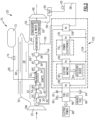
- FIG. 2 another example engine embodiment is indicated at 25 and includes a sealed cooling circuit 102 for transferring thermal energy from the heat producing electrical devices 76, 80 and 86.
- the sealed cooling circuit 102 recovers thermal energy from each of the devices 76, 80 and 86 through corresponding heat exchangers 78, 82 and 88 with a coolant 104 that circulates with the circuit 102.
- the coolant 104 transfers the thermal energy within a circuit heat exchanger 102 to the water flow 58 to generate the heated water flow 100.
- the use of the closed circuit 102 and coolant 104 can simplify recovery of heat by concentrating the transfer of heat into the water flow 58 in one location.
- the coolant 104 may be of any known composition capable of operating at temperatures encountered for each of the electrical devices 76 80 and 86.
- circuit 102 is shown as a simplified schematic view, but may include additional pumps, condensers and valving required to facilitate heating, cooling and transference of thermal energy from the coolant 104 to the water flow 58.
- example engine 20 is described and shown by way of example other engine configurations would benefit from this disclosure and are within the contemplation and scope of this disclosure. Moreover, it will be appreciated that other engine configurations may include additional structures and features and are within the contemplation and scope of this disclosure.
- the disclosed assemblies provide for recovery of thermal energy input into a cooling water flow used as a heat sink to improve engine efficiency.
Landscapes
- Engineering & Computer Science (AREA)
- Chemical & Material Sciences (AREA)
- Combustion & Propulsion (AREA)
- Mechanical Engineering (AREA)
- General Engineering & Computer Science (AREA)
- Aviation & Aerospace Engineering (AREA)
- Engine Equipment That Uses Special Cycles (AREA)
Applications Claiming Priority (2)
| Application Number | Priority Date | Filing Date | Title |
|---|---|---|---|
| US202363441565P | 2023-01-27 | 2023-01-27 | |
| US18/329,091 US20240254898A1 (en) | 2023-01-27 | 2023-06-05 | Power electronics waste heat recovery in recuperation cycle |
Publications (1)
| Publication Number | Publication Date |
|---|---|
| EP4407160A1 true EP4407160A1 (de) | 2024-07-31 |
Family
ID=88965115
Family Applications (1)
| Application Number | Title | Priority Date | Filing Date |
|---|---|---|---|
| EP23211847.1A Pending EP4407160A1 (de) | 2023-01-27 | 2023-11-23 | Abwärmerückgewinnung aus leistungselektronik in einem rückgewinnungszyklus |
Country Status (2)
| Country | Link |
|---|---|
| US (1) | US20240254898A1 (de) |
| EP (1) | EP4407160A1 (de) |
Cited By (1)
| Publication number | Priority date | Publication date | Assignee | Title |
|---|---|---|---|---|
| EP4632203A1 (de) * | 2024-04-09 | 2025-10-15 | Pratt & Whitney Canada Corp. | Energieerzeugungsvorrichtung |
Families Citing this family (2)
| Publication number | Priority date | Publication date | Assignee | Title |
|---|---|---|---|---|
| EP4559813A1 (de) * | 2022-07-21 | 2025-05-28 | IHI Corporation | Hybrides flugzeugantriebsstromquellensystem und verfahren zur steuerung davon |
| US12421895B2 (en) * | 2024-02-01 | 2025-09-23 | General Electric Company | Turbine engine including a condenser system |
Citations (6)
| Publication number | Priority date | Publication date | Assignee | Title |
|---|---|---|---|---|
| JP2013015048A (ja) * | 2011-07-01 | 2013-01-24 | Mitsubishi Heavy Ind Ltd | ガスタービン発電設備 |
| EP3048281A1 (de) * | 2015-01-22 | 2016-07-27 | Rolls-Royce plc | Flugzeugantriebssystem mit einem geschlossenen arbeitszyklus und kondensator |
| US20170211473A1 (en) * | 2014-09-29 | 2017-07-27 | Kawasaki Jukogyo Kabushiki Kaisha | Gas turbine |
| US20210207500A1 (en) * | 2018-05-22 | 2021-07-08 | MTU Aero Engines AG | Exhaust-gas treatment device, aircraft propulsion system, and method for treating an exhaust-gas stream |
| US20220403782A1 (en) * | 2021-06-16 | 2022-12-22 | Pratt & Whitney Canada Corp. | Turbofan engine, cooling system and method of cooling an electric machine |
| EP4303415A1 (de) * | 2022-07-08 | 2024-01-10 | RTX Corporation | Hybrider elektrischer wasserstoffmotor für flugzeuge |
Family Cites Families (10)
| Publication number | Priority date | Publication date | Assignee | Title |
|---|---|---|---|---|
| US4248039A (en) * | 1978-12-06 | 1981-02-03 | International Power Technology, Inc. | Regenerative parallel compound dual fluid heat engine |
| US6880344B2 (en) * | 2002-11-13 | 2005-04-19 | Utc Power, Llc | Combined rankine and vapor compression cycles |
| US20150377179A1 (en) * | 2012-02-08 | 2015-12-31 | Ramesh C. Nayar | Low Grade Thermal Energy Innovative Use |
| US20130286591A1 (en) * | 2012-04-30 | 2013-10-31 | General Electric Company | Power Electronics Cooling |
| US20140137564A1 (en) * | 2012-11-19 | 2014-05-22 | General Electric Company | Mitigation of Hot Corrosion in Steam Injected Gas Turbines |
| US10158138B2 (en) * | 2015-11-30 | 2018-12-18 | Honeywell International Inc. | Systems and methods for fuel desulfurization |
| US10823066B2 (en) * | 2015-12-09 | 2020-11-03 | General Electric Company | Thermal management system |
| US10989117B2 (en) * | 2018-09-14 | 2021-04-27 | Raytheon Technologies Corporation | Hybrid expander cycle with pre-compression cooling and turbo-generator |
| US11946419B2 (en) * | 2022-02-23 | 2024-04-02 | General Electric Company | Methods and apparatus to produce hydrogen gas turbine propulsion |
| GB202205244D0 (en) * | 2022-04-11 | 2022-05-25 | Rolls Royce Plc | Hydrogen fuelled aircraft power system |
-
2023
- 2023-06-05 US US18/329,091 patent/US20240254898A1/en not_active Abandoned
- 2023-11-23 EP EP23211847.1A patent/EP4407160A1/de active Pending
Patent Citations (6)
| Publication number | Priority date | Publication date | Assignee | Title |
|---|---|---|---|---|
| JP2013015048A (ja) * | 2011-07-01 | 2013-01-24 | Mitsubishi Heavy Ind Ltd | ガスタービン発電設備 |
| US20170211473A1 (en) * | 2014-09-29 | 2017-07-27 | Kawasaki Jukogyo Kabushiki Kaisha | Gas turbine |
| EP3048281A1 (de) * | 2015-01-22 | 2016-07-27 | Rolls-Royce plc | Flugzeugantriebssystem mit einem geschlossenen arbeitszyklus und kondensator |
| US20210207500A1 (en) * | 2018-05-22 | 2021-07-08 | MTU Aero Engines AG | Exhaust-gas treatment device, aircraft propulsion system, and method for treating an exhaust-gas stream |
| US20220403782A1 (en) * | 2021-06-16 | 2022-12-22 | Pratt & Whitney Canada Corp. | Turbofan engine, cooling system and method of cooling an electric machine |
| EP4303415A1 (de) * | 2022-07-08 | 2024-01-10 | RTX Corporation | Hybrider elektrischer wasserstoffmotor für flugzeuge |
Cited By (1)
| Publication number | Priority date | Publication date | Assignee | Title |
|---|---|---|---|---|
| EP4632203A1 (de) * | 2024-04-09 | 2025-10-15 | Pratt & Whitney Canada Corp. | Energieerzeugungsvorrichtung |
Also Published As
| Publication number | Publication date |
|---|---|
| US20240254898A1 (en) | 2024-08-01 |
Similar Documents
| Publication | Publication Date | Title |
|---|---|---|
| EP4407160A1 (de) | Abwärmerückgewinnung aus leistungselektronik in einem rückgewinnungszyklus | |
| EP4321744B1 (de) | Zwischengekühlte vorwärmung eines dampfeinspritzenden turbinenmotors | |
| EP3623603B1 (de) | Hybridexpanderzyklus mit turbogenerator und gekühlter leistungselektronik | |
| EP4707575A2 (de) | Wasserabscheider für wasserstoffgetriebenen turbinenmotor | |
| US12098645B2 (en) | Superheated steam injection turbine engine | |
| EP4279718A1 (de) | Wasserstoffbetriebener kondensatorkanal eines turbinenmotors | |
| US12180893B2 (en) | Hydrogen steam injected turbine engine with turboexpander heat recovery | |
| US12078104B2 (en) | Hydrogen steam injected and inter-cooled turbine engine | |
| EP4517070A1 (de) | Wärmetauscher bypass-ejektor | |
| EP4279719A1 (de) | Wasserstoffdampfeinspritzturbinenmotor mit gekühlter kühlluft | |
| EP4279721B1 (de) | Wasserstoffdampfeinspritzturbinenmotor mit rückströmung | |
| EP4411121A1 (de) | Wärmetauscherbypass für den bottoming-zyklus eines turbinenmotors | |
| US12473858B2 (en) | Partial exhaust bottoming cycle | |
| US20240360791A1 (en) | Cryo-assisted bottoming cycle heat source sequencing | |
| US20240359812A1 (en) | Multiple heat source cryogenic bottoming cycle sequencing and routing | |
| CN110758697A (zh) | 动力循环与推进系统及水下航行器 | |
| US20260117699A1 (en) | Pylon-mounted bottoming cycle | |
| EP4678893A1 (de) | Kryounterstützte bottoming-zyklus-wärmequellensequenzierung | |
| US20260015969A1 (en) | Fuel cell exhaust condensation with turbomachinery water augmentation using cryogenic bottoming cycle | |
| EP4678894A2 (de) | Kryogene bottoming-zyklussequenzierung mit mehreren wärmequellen und routing | |
| EP4678891A2 (de) | Kryogenunterstützter bottoming-zyklus |
Legal Events
| Date | Code | Title | Description |
|---|---|---|---|
| PUAI | Public reference made under article 153(3) epc to a published international application that has entered the european phase |
Free format text: ORIGINAL CODE: 0009012 |
|
| STAA | Information on the status of an ep patent application or granted ep patent |
Free format text: STATUS: THE APPLICATION HAS BEEN PUBLISHED |
|
| AK | Designated contracting states |
Kind code of ref document: A1 Designated state(s): AL AT BE BG CH CY CZ DE DK EE ES FI FR GB GR HR HU IE IS IT LI LT LU LV MC ME MK MT NL NO PL PT RO RS SE SI SK SM TR |
|
| STAA | Information on the status of an ep patent application or granted ep patent |
Free format text: STATUS: REQUEST FOR EXAMINATION WAS MADE |
|
| 17P | Request for examination filed |
Effective date: 20250131 |
|
| STAA | Information on the status of an ep patent application or granted ep patent |
Free format text: STATUS: EXAMINATION IS IN PROGRESS |
|
| 17Q | First examination report despatched |
Effective date: 20250618 |