EP4276291A1 - Kondensator für wasserstoffdampfeinspritzturbinenmotor - Google Patents
Kondensator für wasserstoffdampfeinspritzturbinenmotor Download PDFInfo
- Publication number
- EP4276291A1 EP4276291A1 EP23173237.1A EP23173237A EP4276291A1 EP 4276291 A1 EP4276291 A1 EP 4276291A1 EP 23173237 A EP23173237 A EP 23173237A EP 4276291 A1 EP4276291 A1 EP 4276291A1
- Authority
- EP
- European Patent Office
- Prior art keywords
- condenser
- water
- gas flow
- high energy
- passages
- Prior art date
- Legal status (The legal status is an assumption and is not a legal conclusion. Google has not performed a legal analysis and makes no representation as to the accuracy of the status listed.)
- Granted
Links
Images


Classifications
-
- F—MECHANICAL ENGINEERING; LIGHTING; HEATING; WEAPONS; BLASTING
- F02—COMBUSTION ENGINES; HOT-GAS OR COMBUSTION-PRODUCT ENGINE PLANTS
- F02C—GAS-TURBINE PLANTS; AIR INTAKES FOR JET-PROPULSION PLANTS; CONTROLLING FUEL SUPPLY IN AIR-BREATHING JET-PROPULSION PLANTS
- F02C7/00—Features, components parts, details or accessories, not provided for in, or of interest apart form groups F02C1/00 - F02C6/00; Air intakes for jet-propulsion plants
- F02C7/12—Cooling of plants
- F02C7/14—Cooling of plants of fluids in the plant, e.g. lubricant or fuel
- F02C7/141—Cooling of plants of fluids in the plant, e.g. lubricant or fuel of working fluid
-
- F—MECHANICAL ENGINEERING; LIGHTING; HEATING; WEAPONS; BLASTING
- F02—COMBUSTION ENGINES; HOT-GAS OR COMBUSTION-PRODUCT ENGINE PLANTS
- F02K—JET-PROPULSION PLANTS
- F02K1/00—Plants characterised by the form or arrangement of the jet pipe or nozzle; Jet pipes or nozzles peculiar thereto
- F02K1/78—Other construction of jet pipes
- F02K1/82—Jet pipe walls, e.g. liners
- F02K1/822—Heat insulating structures or liners, cooling arrangements, e.g. post combustion liners; Infrared radiation suppressors
-
- B—PERFORMING OPERATIONS; TRANSPORTING
- B01—PHYSICAL OR CHEMICAL PROCESSES OR APPARATUS IN GENERAL
- B01D—SEPARATION
- B01D53/00—Separation of gases or vapours; Recovering vapours of volatile solvents from gases; Chemical or biological purification of waste gases, e.g. engine exhaust gases, smoke, fumes, flue gases, aerosols
- B01D53/26—Drying gases or vapours
- B01D53/265—Drying gases or vapours by refrigeration (condensation)
-
- F—MECHANICAL ENGINEERING; LIGHTING; HEATING; WEAPONS; BLASTING
- F01—MACHINES OR ENGINES IN GENERAL; ENGINE PLANTS IN GENERAL; STEAM ENGINES
- F01D—NON-POSITIVE DISPLACEMENT MACHINES OR ENGINES, e.g. STEAM TURBINES
- F01D25/00—Component parts, details, or accessories, not provided for in, or of interest apart from, other groups
- F01D25/08—Cooling; Heating; Heat-insulation
- F01D25/12—Cooling
-
- F—MECHANICAL ENGINEERING; LIGHTING; HEATING; WEAPONS; BLASTING
- F01—MACHINES OR ENGINES IN GENERAL; ENGINE PLANTS IN GENERAL; STEAM ENGINES
- F01D—NON-POSITIVE DISPLACEMENT MACHINES OR ENGINES, e.g. STEAM TURBINES
- F01D25/00—Component parts, details, or accessories, not provided for in, or of interest apart from, other groups
- F01D25/30—Exhaust heads, chambers, or the like
-
- F—MECHANICAL ENGINEERING; LIGHTING; HEATING; WEAPONS; BLASTING
- F01—MACHINES OR ENGINES IN GENERAL; ENGINE PLANTS IN GENERAL; STEAM ENGINES
- F01D—NON-POSITIVE DISPLACEMENT MACHINES OR ENGINES, e.g. STEAM TURBINES
- F01D25/00—Component parts, details, or accessories, not provided for in, or of interest apart from, other groups
- F01D25/32—Collecting of condensation water; Drainage ; Removing solid particles
-
- F—MECHANICAL ENGINEERING; LIGHTING; HEATING; WEAPONS; BLASTING
- F02—COMBUSTION ENGINES; HOT-GAS OR COMBUSTION-PRODUCT ENGINE PLANTS
- F02C—GAS-TURBINE PLANTS; AIR INTAKES FOR JET-PROPULSION PLANTS; CONTROLLING FUEL SUPPLY IN AIR-BREATHING JET-PROPULSION PLANTS
- F02C3/00—Gas-turbine plants characterised by the use of combustion products as the working fluid
- F02C3/20—Gas-turbine plants characterised by the use of combustion products as the working fluid using a special fuel, oxidant, or dilution fluid to generate the combustion products
- F02C3/22—Gas-turbine plants characterised by the use of combustion products as the working fluid using a special fuel, oxidant, or dilution fluid to generate the combustion products the fuel or oxidant being gaseous at standard temperature and pressure
-
- F—MECHANICAL ENGINEERING; LIGHTING; HEATING; WEAPONS; BLASTING
- F02—COMBUSTION ENGINES; HOT-GAS OR COMBUSTION-PRODUCT ENGINE PLANTS
- F02C—GAS-TURBINE PLANTS; AIR INTAKES FOR JET-PROPULSION PLANTS; CONTROLLING FUEL SUPPLY IN AIR-BREATHING JET-PROPULSION PLANTS
- F02C3/00—Gas-turbine plants characterised by the use of combustion products as the working fluid
- F02C3/20—Gas-turbine plants characterised by the use of combustion products as the working fluid using a special fuel, oxidant, or dilution fluid to generate the combustion products
- F02C3/30—Adding water, steam or other fluids for influencing combustion, e.g. to obtain cleaner exhaust gases
- F02C3/305—Increasing the power, speed, torque or efficiency of a gas turbine or the thrust of a turbojet engine by injecting or adding water, steam or other fluids
-
- B—PERFORMING OPERATIONS; TRANSPORTING
- B01—PHYSICAL OR CHEMICAL PROCESSES OR APPARATUS IN GENERAL
- B01D—SEPARATION
- B01D2258/00—Sources of waste gases
- B01D2258/01—Engine exhaust gases
-
- B—PERFORMING OPERATIONS; TRANSPORTING
- B01—PHYSICAL OR CHEMICAL PROCESSES OR APPARATUS IN GENERAL
- B01D—SEPARATION
- B01D2259/00—Type of treatment
- B01D2259/45—Gas separation or purification devices adapted for specific applications
- B01D2259/4566—Gas separation or purification devices adapted for specific applications for use in transportation means
- B01D2259/4575—Gas separation or purification devices adapted for specific applications for use in transportation means in aeroplanes or space ships
-
- F—MECHANICAL ENGINEERING; LIGHTING; HEATING; WEAPONS; BLASTING
- F05—INDEXING SCHEMES RELATING TO ENGINES OR PUMPS IN VARIOUS SUBCLASSES OF CLASSES F01-F04
- F05D—INDEXING SCHEME FOR ASPECTS RELATING TO NON-POSITIVE-DISPLACEMENT MACHINES OR ENGINES, GAS-TURBINES OR JET-PROPULSION PLANTS
- F05D2220/00—Application
- F05D2220/30—Application in turbines
- F05D2220/32—Application in turbines in gas turbines
- F05D2220/323—Application in turbines in gas turbines for aircraft propulsion, e.g. jet engines
-
- F—MECHANICAL ENGINEERING; LIGHTING; HEATING; WEAPONS; BLASTING
- F05—INDEXING SCHEMES RELATING TO ENGINES OR PUMPS IN VARIOUS SUBCLASSES OF CLASSES F01-F04
- F05D—INDEXING SCHEME FOR ASPECTS RELATING TO NON-POSITIVE-DISPLACEMENT MACHINES OR ENGINES, GAS-TURBINES OR JET-PROPULSION PLANTS
- F05D2220/00—Application
- F05D2220/60—Application making use of surplus or waste energy
-
- F—MECHANICAL ENGINEERING; LIGHTING; HEATING; WEAPONS; BLASTING
- F05—INDEXING SCHEMES RELATING TO ENGINES OR PUMPS IN VARIOUS SUBCLASSES OF CLASSES F01-F04
- F05D—INDEXING SCHEME FOR ASPECTS RELATING TO NON-POSITIVE-DISPLACEMENT MACHINES OR ENGINES, GAS-TURBINES OR JET-PROPULSION PLANTS
- F05D2260/00—Function
- F05D2260/20—Heat transfer, e.g. cooling
- F05D2260/213—Heat transfer, e.g. cooling by the provision of a heat exchanger within the cooling circuit
-
- F—MECHANICAL ENGINEERING; LIGHTING; HEATING; WEAPONS; BLASTING
- F05—INDEXING SCHEMES RELATING TO ENGINES OR PUMPS IN VARIOUS SUBCLASSES OF CLASSES F01-F04
- F05D—INDEXING SCHEME FOR ASPECTS RELATING TO NON-POSITIVE-DISPLACEMENT MACHINES OR ENGINES, GAS-TURBINES OR JET-PROPULSION PLANTS
- F05D2260/00—Function
- F05D2260/20—Heat transfer, e.g. cooling
- F05D2260/221—Improvement of heat transfer
- F05D2260/2214—Improvement of heat transfer by increasing the heat transfer surface
-
- F—MECHANICAL ENGINEERING; LIGHTING; HEATING; WEAPONS; BLASTING
- F05—INDEXING SCHEMES RELATING TO ENGINES OR PUMPS IN VARIOUS SUBCLASSES OF CLASSES F01-F04
- F05D—INDEXING SCHEME FOR ASPECTS RELATING TO NON-POSITIVE-DISPLACEMENT MACHINES OR ENGINES, GAS-TURBINES OR JET-PROPULSION PLANTS
- F05D2260/00—Function
- F05D2260/60—Fluid transfer
Definitions
- the present invention relates generally to a hydrogen powered aircraft propulsion system and, more particularly to hydrogen steam injected and intercooled turbine engine.
- Turbine engine manufacturers continue to seek further improvements to engine performance including improvements to reduce environmental impact while improving propulsive efficiencies.
- a propulsion system for an aircraft includes a core engine that includes a core flow path where air is compressed in a compressor section, communicated to a combustor section, mixed with a hydrogen based fuel and ignited to generate a high energy gas flow that is expanded through a turbine section.
- a hydrogen fuel system is configured to supply hydrogen fuel to the combustor through a fuel flow path.
- a condenser is arranged along the core flow path and is configured to extract water from the high energy gas flow. The condenser includes a plurality of rotating passages that are disposed in a collector.
- the passages are configured to rotate about a condenser axis to generate a transverse pressure gradient to direct water out of the high energy gas flow toward the collector.
- An evaporator is arranged along the core flow path and is configured to receive a portion of the water that is extracted by the condenser to generate a steam flow. The steam flow is injected into the core flow path upstream of the turbine section.
- the condenser is configured to receive a cooling flow to cool the high energy gas flow.
- the condenser is configured to receive the cooling flow at a location along an outer periphery.
- the plurality of rotating passages include a plurality of spiral layers that extend axially about a condenser axis.
- the plurality of spiral layers include openings that are configured to exhaust water that is collected from the high energy gas flow to the collector.
- the condenser includes a plurality of axial passages and a plurality of transition passages for directing the high energy gas flow into the rotating passages.
- the propulsion system includes a shaft that is disposed along the condenser axis for supporting rotation of the rotating passages.
- the propulsion system includes a motor that is coupled to the shaft and is configured to drive rotation of the rotating passages.
- the plurality of rotating passages is configured to rotate about the shaft in response to an axial momentum of the high energy gas flow.
- the plurality of rotating passages include a hydrophilic coating.
- the plurality of rotating passages include a hydrophobic coating.
- the plurality of rotating include a textured surface.
- the propulsion system includes a water storage tank and the collector is configured to communicate water that is extracted from the high energy gas flow to the water storage tank.
- a water recovery system for an aircraft propulsion system, according to an exemplary embodiment of this invention, among other possible things includes a condenser that is arranged along a core flow path of a propulsion system and is configured to extract water from a high energy gas flow.
- the condenser includes a plurality of rotating passages that are disposed in a collector. The passages are configured to rotate about a condenser axis to generate a transverse pressure gradient to direct water out of the high energy gas flow toward the collector.
- a water storage tank is in communication with the collector that is configured to receive water that is extracted from the high energy gas flow to the water storage tank.
- the water recovery system includes at least one water pump for communicating water from the water storage tank to the propulsion system.
- the condenser is configured to receive a cooling flow to cool the high energy gas flow within the plurality of rotating passages.
- Athe plurality of rotating passages are defined between a plurality of curved layers that extend axially and curve about a condenser axis.
- the water recovery system includes a shaft that supports the plurality of rotating passages for rotation about the condenser axis.
- the water recovery system includes a motor that is coupled to the shaft to drive rotation of the plurality of rotating passages.
- the plurality of rotating passages include at least one of a hydrophilic coating, a hydrophobic coating or a textured surface.
- a method of operating an aircraft propulsion system includes generating a high energy gas flow that includes water, removing water from the high energy gas flow with a rotating portion of a condenser that is disposed in a flow path downstream from a combustor, generating a steam flow from water removed from the high energy gas flow with an evaporator that is located within the flow path upstream of the condenser and downstream of the combustor, and injecting the generated steam with a core flow path.
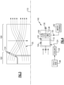
- FIG. 1 schematically illustrates an aircraft propulsion system in the form of an example hydrogen steam injected inter-cooled turbine engine that is generally indicated at 20.
- the engine 20 includes a core engine with a core airflow path C through a fan 22, a compressor section 24, a combustor 30 and a turbine section 32.
- the fan 22 drives inlet air as a core flow 25 into the compressor section 24.
- the core flow 25 is compressed and communicated to a combustor 30.
- the core flow 25 is mixed with a hydrogen (H 2 ) fuel flow 45 and ignited to generate a high energy gas flow 55 that expands through the turbine section 32 where energy is extracted and utilized to drive the fan 22 and the compressor section 24.
- H 2 hydrogen
- a bypass flow 18 may flow through the fan 22, bypass the remaining components of the engine 20, and exit through a fan nozzle 94.
- the high energy gas flow 55 is exhausted from the turbine section 32 and communicated to a steam generation system 70 and a water recovery system 78 before being exhausted through a core nozzle 96.
- the engine 20 is configured to burn hydrogen provide by a fuel system 52.
- the fuel system 52 includes a liquid hydrogen (LH 2 ) tank 54 in communication with at least one pump 56.
- the pump 56 drives a fuel flow 45 to the combustor 30.
- LH 2 provides a thermal heat sink that can be utilized to cool various heat loads within the aircraft indicated at 60 and in the engine as indicated at 62.
- the heat loads may include, for example and without limitation, super conducting electrics, a working fluid of an environmental control system of the aircraft, an air conditioning heat exchanger, and engine working fluid heat exchangers. Heat accepted into the hydrogen fuel flow increase the overall fuel temperature prior to injection into the combustor 30.
- a hydrogen expansion turbine 58 may be provided to reduce the pressure of the LH 2 fuel flow through expansion prior to communication to the combustor 30. Expansion in the expansion turbine 58 provides for the temperatures and pressures of the fuel flow to enter the combustor 30 as a gas and not a liquid.
- the steam injection system 70 uses the exhaust heat to generate a steam flow by evaporating high pressure water through an evaporator 72.
- the generated steam may then be injected into compressed core airflow at a location 76 for communication into the combustor 30 to improve performance by increasing turbine mass flow and power output without additional work required by the compressor section.
- the location 76 is upstream of the combustor 30.
- Steam flow from the evaporator 72 may drive a steam turbine 74 to provide an additional work output prior to injection into the combustor 30.
- the water recovery system 78 draws water, schematically indicated at 35, from the high energy gas flow 55 and communicates the recovered water to water storage tank 82.
- the water storage tank 82 operates as an accumulator to provide sufficient water for operation during various engine operating conditions.
- a condenser/water separator 80 is provided downstream of the turbine section 32 and the evaporator 72.
- the condenser/separator 80 is in communication with a cold sink, schematically indicated at 98 for the condenser/separator 80 may be, for example, ram or fan air depending on the application and/or engine configuration.
- the engine 20 has an increased power output from the injected steam due to an increasing mass flow through the turbine section 32 without a corresponding increase in work from the compressor section 24.
- An example engine operation cycle may include up to (or more than) 35% steam-air-ratios (SAR) and may be assisted by a multiple fold (e.g., 2x, 3x, etc.) increase in moisture from burning H 2 as the fuel.
- SAR steam-air-ratios
- the water recovery system 78 includes the water storage tank 82 that receives water from the condenser/water separator 80 and provides for the accumulation of a volume of water required for production of sufficient amounts of steam. Water recovered from the exhaust gas flow is driven by a low pressure pump 84 and a high pressure pump 86 to the evaporator 72.
- a water intercooling flow 88 may be communicated to the compressor section 24 to reduce a temperature of the core airflow 25 and increase mass flow. Reduced temperatures and increased mass flow provided by injection of water increases compressor efficiency. Water may also be used as a cooling flow 92 to cool cooling air flow 90 communicated from the compressor section 24 to the turbine section 32.
- the example compressor section 24 includes a low pressure compressor (LPC) 26 and a high pressure compressor (HPC) 28.
- the turbine section 32 includes a high pressure turbine (HPT) 34, an intermediate pressure turbine (IPT) 36, and a low pressure turbine (LPT) 38.
- the turbines 34, 36 and 38 are coupled to a corresponding compressor section.
- the high pressure turbine is coupled by a high shaft 64 to drive the high pressure compressor 28.
- An intermediate shaft 66 couples the intermediate turbine 36 to the low pressure compressor 26.
- a low shaft 68 is coupled to the low pressure turbine 38 and a gearbox 40 to drive the fan 22.
- the low shaft 68 may further be coupled to an electric machine 42 that is configured to impart and/or extract power into the low shaft 68.
- the example gearbox 40 is an epicyclical gear train, such as a planetary gear system, star gear system or other known gear system, with a gear reduction ratio of greater than about 2.3.
- example engine 20 is described and shown by way of example as a three spool engine, other engine configurations, such as two-spool may also benefit from this disclosure and are within the contemplation and scope of this disclosure.
- the condenser 80 includes a plurality of rotating passages 100 that rotate to induce a centrifugal force on water from the gas flow 55.
- a coolant flow 124 from a coolant reservoir 122 is placed in thermal communication with the gas flow 55 to transform a portion of steam into liquid water.
- the liquid water, schematically indicated at 116 is directed by a collector 112 through an opening 114 to the water storage 82.
- the coolant flow 124 is directed to an outer periphery 126 of the condenser 80 and into thermal communication with the gas flow 55.
- the rotating passages 100 are disposed about a condenser axis 110 and supported on a shaft 128.
- the shaft 128 is supported by bearing systems 130 in one disclosed embodiment.
- the condenser 80 includes a first axial portion 104 that initially received the gas flow 55.
- a transition region 102 is disposed between the axil portion 104 and the rotating passages 100.
- the transition region 102 induces an initial swirl on the incoming gas flow 55. From the transition region, the gas flow 55 enters the rotating passages 100.
- the gas flow 55 in the rotating passages 100 includes an axial component 120 and a transverse component 118.
- the transverse component 118 provides for the heavier liquid water to be driven radially outward into the collector 112.
- the collector 112 surrounds the rotating passages and includes at least one opening 114 for liquid water condensate water flow. It should be appreciated that the collector 112 may include a plurality of openings 114 arranged to capture water flow 116 at various axial and radial locations.
- a motor 132 is coupled to the shaft 128 to rotate the rotating passages 100.
- the motor 132 is configured to rotate the passages 100 at a predefined speed determined to generate sufficient centrifugal forces in the direction indicated at 118 to drive liquid water flow 116 outward into the collector 112.
- the collector 112 is a formed sheet material that substantially surrounds the passages through the axis portion 104, the transition region 102 and the rotating passages 100.
- the passages through the condenser 80 maybe formed from sheet metal material, as a cast part or by additive manufacturing processes. Moreover, it should be appreciated that it is within the contemplation and scope of this disclosure that the example condenser 80 may be formed using other manufacturing and assembly processes.
- the rotating passages 100 and the transition region are schematically shown with gas flows 55 and the coolant flow 124.
- the gas flow 55 and the coolant flow 124 are maintained separately although in thermal communication.
- the coolant flow 124 is comprised of a coolant that is allowed to mix with exhausted gas flows 55 that are exhausted from the condenser 80.
- FIG. 4 another example condenser embodiment is schematically shown and indicated at 140.
- the example condenser 140 includes the same features as the previously described condenser 80 but does not include the motor 132. Instead, the condenser 140 uses the axial momentum of the high energy exhaust gas flow 55 to drive rotation of the plurality of rotating passages 100.
- the rotating passages 100 are spiral shaped such that as the axial gas flow 55 impacts sides of the passages 100, an auto rotation is induced that provides the desired centrifugal forces to separate the liquids as a water flow.
- the passages 100 are supported on the shaft 128 and bearings 130 and uses the inherent momentum of the gas flow 55 to drive rotation.
- the rotating passages 100 may be configured to auto rotate in some engine operating conditions according to the example described in Figure 4 and also may include a motor 132 to drive rotation in other operating conditions. Accordingly, the motor 132 may be provided and used only during specific operating conditions where the momentum of the gas flow 55 may not provide the desired magnitude of centrifugal force.
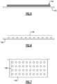
- surfaces 142 of the passages 100 may be provided with a coating 144 that aids in the condensation of water from the gas flow 55.
- the coating 144 comprise a hydrophilic material.
- the coating 144 comprises a hydrophobic material.
- the coating 144 may be a pattern of alternating sections made from a hydrophobic material and other sections including hydrophilic material to drive and gather condensate from the gas flow 55.
- surfaces 146 within the example condensers 80, 140 maybe textured to enhance thermal transfer into the gas flow 55.
- the surfaces 146 include a texture 148 formed from a plurality of raised bumps.
- the texture 148 may be configured to induce a turbulent flow near the surfaces 146 to enhance thermal transfer and thereby accelerate cooling and liquid extraction.
- example condensers 80, 140 provide for the transformation of water in gas form within the gas flow into liquid water that is then separated and stored for injection back into the engine to improve overall propulsive system efficiency.
- the disclosed assemblies provide for the advantageous use of hydrogen fuel to improve engine efficiency and reduce carbon emission.
- the disclosed systems use the advantageous thermal capacity of hydrogen to maximize the recapture of heat and cool other working flows of the engine.
Landscapes
- Engineering & Computer Science (AREA)
- Chemical & Material Sciences (AREA)
- Mechanical Engineering (AREA)
- General Engineering & Computer Science (AREA)
- Combustion & Propulsion (AREA)
- Thermal Sciences (AREA)
- Physics & Mathematics (AREA)
- Analytical Chemistry (AREA)
- General Chemical & Material Sciences (AREA)
- Oil, Petroleum & Natural Gas (AREA)
- Chemical Kinetics & Catalysis (AREA)
- Engine Equipment That Uses Special Cycles (AREA)
- Hydrogen, Water And Hydrids (AREA)
Priority Applications (1)
| Application Number | Priority Date | Filing Date | Title |
|---|---|---|---|
| EP25170201.5A EP4582675A3 (de) | 2022-05-13 | 2023-05-12 | Kondensator für eine mit wasserstoffdampf injizierte brennkraftmaschine |
Applications Claiming Priority (1)
| Application Number | Priority Date | Filing Date | Title |
|---|---|---|---|
| US17/744,379 US11920515B2 (en) | 2022-05-13 | 2022-05-13 | Condenser for hydrogen steam injected turbine engine |
Related Child Applications (1)
| Application Number | Title | Priority Date | Filing Date |
|---|---|---|---|
| EP25170201.5A Division EP4582675A3 (de) | 2022-05-13 | 2023-05-12 | Kondensator für eine mit wasserstoffdampf injizierte brennkraftmaschine |
Publications (2)
| Publication Number | Publication Date |
|---|---|
| EP4276291A1 true EP4276291A1 (de) | 2023-11-15 |
| EP4276291B1 EP4276291B1 (de) | 2025-04-16 |
Family
ID=86378338
Family Applications (2)
| Application Number | Title | Priority Date | Filing Date |
|---|---|---|---|
| EP23173237.1A Active EP4276291B1 (de) | 2022-05-13 | 2023-05-12 | Kondensator für wasserstoffdampfeinspritzturbinenmotor |
| EP25170201.5A Pending EP4582675A3 (de) | 2022-05-13 | 2023-05-12 | Kondensator für eine mit wasserstoffdampf injizierte brennkraftmaschine |
Family Applications After (1)
| Application Number | Title | Priority Date | Filing Date |
|---|---|---|---|
| EP25170201.5A Pending EP4582675A3 (de) | 2022-05-13 | 2023-05-12 | Kondensator für eine mit wasserstoffdampf injizierte brennkraftmaschine |
Country Status (2)
| Country | Link |
|---|---|
| US (1) | US11920515B2 (de) |
| EP (2) | EP4276291B1 (de) |
Cited By (1)
| Publication number | Priority date | Publication date | Assignee | Title |
|---|---|---|---|---|
| EP4474624A3 (de) * | 2023-05-19 | 2025-02-26 | RTX Corporation | Wasserabscheider für einen turbinenmotor |
Families Citing this family (5)
| Publication number | Priority date | Publication date | Assignee | Title |
|---|---|---|---|---|
| US12523176B2 (en) | 2022-06-22 | 2026-01-13 | General Electric Company | Gearbox assembly with lubricant extraction volume ratio |
| EP4390088A1 (de) * | 2022-12-21 | 2024-06-26 | MTU Aero Engines AG | Verfahren zum betreiben einer strömungsmaschine für einen flugantrieb |
| US12031485B1 (en) * | 2023-04-21 | 2024-07-09 | Rtx Corporation | Water storage precooling and water cycle chiller |
| US12221905B1 (en) * | 2023-08-07 | 2025-02-11 | General Electric Company | Turbine engine including a steam system |
| US20250369393A1 (en) * | 2024-05-30 | 2025-12-04 | Rtx Corporation | Axial flow angled condenser arrangement for an aircraft propulsion system |
Citations (4)
| Publication number | Priority date | Publication date | Assignee | Title |
|---|---|---|---|---|
| GB2531632A (en) * | 2015-08-10 | 2016-04-27 | Latif Qureshi Masood | A mechanical device to suppress contrail formation |
| EP3048281A1 (de) * | 2015-01-22 | 2016-07-27 | Rolls-Royce plc | Flugzeugantriebssystem mit einem geschlossenen arbeitszyklus und kondensator |
| US20210001269A1 (en) * | 2018-03-02 | 2021-01-07 | MTU Aero Engines AG | Reducing contrails during operation of aircraft |
| US20210207500A1 (en) * | 2018-05-22 | 2021-07-08 | MTU Aero Engines AG | Exhaust-gas treatment device, aircraft propulsion system, and method for treating an exhaust-gas stream |
Family Cites Families (4)
| Publication number | Priority date | Publication date | Assignee | Title |
|---|---|---|---|---|
| US3657879A (en) * | 1970-01-26 | 1972-04-25 | Walter J Ewbank | Gas-steam engine |
| US4248039A (en) * | 1978-12-06 | 1981-02-03 | International Power Technology, Inc. | Regenerative parallel compound dual fluid heat engine |
| US10247408B2 (en) * | 2014-11-14 | 2019-04-02 | University Of Florida Research Foundation, Inc. | Humid air turbine power, water extraction, and refrigeration cycle |
| GB202114829D0 (en) * | 2021-10-18 | 2021-12-01 | Rolls Royce Plc | Aircraft propulsion system |
-
2022
- 2022-05-13 US US17/744,379 patent/US11920515B2/en active Active
-
2023
- 2023-05-12 EP EP23173237.1A patent/EP4276291B1/de active Active
- 2023-05-12 EP EP25170201.5A patent/EP4582675A3/de active Pending
Patent Citations (4)
| Publication number | Priority date | Publication date | Assignee | Title |
|---|---|---|---|---|
| EP3048281A1 (de) * | 2015-01-22 | 2016-07-27 | Rolls-Royce plc | Flugzeugantriebssystem mit einem geschlossenen arbeitszyklus und kondensator |
| GB2531632A (en) * | 2015-08-10 | 2016-04-27 | Latif Qureshi Masood | A mechanical device to suppress contrail formation |
| US20210001269A1 (en) * | 2018-03-02 | 2021-01-07 | MTU Aero Engines AG | Reducing contrails during operation of aircraft |
| US20210207500A1 (en) * | 2018-05-22 | 2021-07-08 | MTU Aero Engines AG | Exhaust-gas treatment device, aircraft propulsion system, and method for treating an exhaust-gas stream |
Cited By (1)
| Publication number | Priority date | Publication date | Assignee | Title |
|---|---|---|---|---|
| EP4474624A3 (de) * | 2023-05-19 | 2025-02-26 | RTX Corporation | Wasserabscheider für einen turbinenmotor |
Also Published As
| Publication number | Publication date |
|---|---|
| US20230366351A1 (en) | 2023-11-16 |
| US11920515B2 (en) | 2024-03-05 |
| EP4276291B1 (de) | 2025-04-16 |
| EP4582675A2 (de) | 2025-07-09 |
| EP4582675A3 (de) | 2025-08-06 |
Similar Documents
| Publication | Publication Date | Title |
|---|---|---|
| US11920515B2 (en) | Condenser for hydrogen steam injected turbine engine | |
| EP4276292B1 (de) | Antriebssystem für ein flugzeug | |
| EP4279722B1 (de) | Wasserabscheider für wasserstoffgetriebenen turbinenmotor | |
| EP4279720B1 (de) | Turbinenmotor mit überhitzter dampfeinspritzung | |
| EP4321744B1 (de) | Zwischengekühlte vorwärmung eines dampfeinspritzenden turbinenmotors | |
| EP4279718B1 (de) | Kondensatorkanal eines wasserstoffbetriebenen turbinenmotors | |
| US12486801B2 (en) | Hydrogen steam injected turbine engine with turboexpander heat recovery | |
| EP4411122A2 (de) | Ein antriebssystem für ein flugzeug | |
| EP4279723A1 (de) | Wasserstoffturbinenmotor mit dampfeinspritzung und zwischenkühlung | |
| EP4414542A1 (de) | Wasserabscheider für wasserstoffdampfeinspritzturbinenmotor | |
| EP4279719B1 (de) | Wasserstoffdampfeinspritzturbinenmotor mit gekühlter kühlluft | |
| EP4722516A2 (de) | Versetzter kern mit seitenausstossgondeldüsen | |
| EP4279721B1 (de) | Wasserstoffdampfeinspritzturbinenmotor mit rückströmung | |
| EP4656860A1 (de) | Konische kondensatoranordnung mit axialer strömung für ein flugzeugantriebssystem |
Legal Events
| Date | Code | Title | Description |
|---|---|---|---|
| PUAI | Public reference made under article 153(3) epc to a published international application that has entered the european phase |
Free format text: ORIGINAL CODE: 0009012 |
|
| STAA | Information on the status of an ep patent application or granted ep patent |
Free format text: STATUS: THE APPLICATION HAS BEEN PUBLISHED |
|
| AK | Designated contracting states |
Kind code of ref document: A1 Designated state(s): AL AT BE BG CH CY CZ DE DK EE ES FI FR GB GR HR HU IE IS IT LI LT LU LV MC ME MK MT NL NO PL PT RO RS SE SI SK SM TR |
|
| STAA | Information on the status of an ep patent application or granted ep patent |
Free format text: STATUS: REQUEST FOR EXAMINATION WAS MADE |
|
| 17P | Request for examination filed |
Effective date: 20240515 |
|
| RBV | Designated contracting states (corrected) |
Designated state(s): AL AT BE BG CH CY CZ DE DK EE ES FI FR GB GR HR HU IE IS IT LI LT LU LV MC ME MK MT NL NO PL PT RO RS SE SI SK SM TR |
|
| GRAP | Despatch of communication of intention to grant a patent |
Free format text: ORIGINAL CODE: EPIDOSNIGR1 |
|
| STAA | Information on the status of an ep patent application or granted ep patent |
Free format text: STATUS: GRANT OF PATENT IS INTENDED |
|
| RIC1 | Information provided on ipc code assigned before grant |
Ipc: F01D 25/12 20060101ALI20241011BHEP Ipc: F02K 1/82 20060101ALI20241011BHEP Ipc: F02C 3/30 20060101ALI20241011BHEP Ipc: F01D 25/32 20060101ALI20241011BHEP Ipc: F01D 25/30 20060101ALI20241011BHEP Ipc: B01D 53/26 20060101ALI20241011BHEP Ipc: B01D 53/24 20060101ALI20241011BHEP Ipc: F02C 3/22 20060101AFI20241011BHEP |
|
| INTG | Intention to grant announced |
Effective date: 20241108 |
|
| GRAS | Grant fee paid |
Free format text: ORIGINAL CODE: EPIDOSNIGR3 |
|
| GRAA | (expected) grant |
Free format text: ORIGINAL CODE: 0009210 |
|
| STAA | Information on the status of an ep patent application or granted ep patent |
Free format text: STATUS: THE PATENT HAS BEEN GRANTED |
|
| AK | Designated contracting states |
Kind code of ref document: B1 Designated state(s): AL AT BE BG CH CY CZ DE DK EE ES FI FR GB GR HR HU IE IS IT LI LT LU LV MC ME MK MT NL NO PL PT RO RS SE SI SK SM TR |
|
| REG | Reference to a national code |
Ref country code: GB Ref legal event code: FG4D |
|
| REG | Reference to a national code |
Ref country code: CH Ref legal event code: EP Ref country code: DE Ref legal event code: R096 Ref document number: 602023002896 Country of ref document: DE |
|
| REG | Reference to a national code |
Ref country code: IE Ref legal event code: FG4D |
|
| PGFP | Annual fee paid to national office [announced via postgrant information from national office to epo] |
Ref country code: DE Payment date: 20250423 Year of fee payment: 3 |
|
| PGFP | Annual fee paid to national office [announced via postgrant information from national office to epo] |
Ref country code: FR Payment date: 20250520 Year of fee payment: 3 |
|
| PGFP | Annual fee paid to national office [announced via postgrant information from national office to epo] |
Ref country code: AT Payment date: 20250721 Year of fee payment: 3 |
|
| REG | Reference to a national code |
Ref country code: NL Ref legal event code: MP Effective date: 20250416 |
|
| PG25 | Lapsed in a contracting state [announced via postgrant information from national office to epo] |
Ref country code: NL Free format text: LAPSE BECAUSE OF FAILURE TO SUBMIT A TRANSLATION OF THE DESCRIPTION OR TO PAY THE FEE WITHIN THE PRESCRIBED TIME-LIMIT Effective date: 20250416 |
|
| REG | Reference to a national code |
Ref country code: AT Ref legal event code: MK05 Ref document number: 1785837 Country of ref document: AT Kind code of ref document: T Effective date: 20250416 |
|
| PG25 | Lapsed in a contracting state [announced via postgrant information from national office to epo] |
Ref country code: PT Free format text: LAPSE BECAUSE OF FAILURE TO SUBMIT A TRANSLATION OF THE DESCRIPTION OR TO PAY THE FEE WITHIN THE PRESCRIBED TIME-LIMIT Effective date: 20250818 Ref country code: FI Free format text: LAPSE BECAUSE OF FAILURE TO SUBMIT A TRANSLATION OF THE DESCRIPTION OR TO PAY THE FEE WITHIN THE PRESCRIBED TIME-LIMIT Effective date: 20250416 Ref country code: ES Free format text: LAPSE BECAUSE OF FAILURE TO SUBMIT A TRANSLATION OF THE DESCRIPTION OR TO PAY THE FEE WITHIN THE PRESCRIBED TIME-LIMIT Effective date: 20250416 |
|
| REG | Reference to a national code |
Ref country code: LT Ref legal event code: MG9D |
|
| PG25 | Lapsed in a contracting state [announced via postgrant information from national office to epo] |
Ref country code: NO Free format text: LAPSE BECAUSE OF FAILURE TO SUBMIT A TRANSLATION OF THE DESCRIPTION OR TO PAY THE FEE WITHIN THE PRESCRIBED TIME-LIMIT Effective date: 20250716 Ref country code: GR Free format text: LAPSE BECAUSE OF FAILURE TO SUBMIT A TRANSLATION OF THE DESCRIPTION OR TO PAY THE FEE WITHIN THE PRESCRIBED TIME-LIMIT Effective date: 20250717 |
|
| PG25 | Lapsed in a contracting state [announced via postgrant information from national office to epo] |
Ref country code: PL Free format text: LAPSE BECAUSE OF FAILURE TO SUBMIT A TRANSLATION OF THE DESCRIPTION OR TO PAY THE FEE WITHIN THE PRESCRIBED TIME-LIMIT Effective date: 20250416 |
|
| PG25 | Lapsed in a contracting state [announced via postgrant information from national office to epo] |
Ref country code: BG Free format text: LAPSE BECAUSE OF FAILURE TO SUBMIT A TRANSLATION OF THE DESCRIPTION OR TO PAY THE FEE WITHIN THE PRESCRIBED TIME-LIMIT Effective date: 20250416 |
|
| PG25 | Lapsed in a contracting state [announced via postgrant information from national office to epo] |
Ref country code: HR Free format text: LAPSE BECAUSE OF FAILURE TO SUBMIT A TRANSLATION OF THE DESCRIPTION OR TO PAY THE FEE WITHIN THE PRESCRIBED TIME-LIMIT Effective date: 20250416 |
|
| PG25 | Lapsed in a contracting state [announced via postgrant information from national office to epo] |
Ref country code: AT Free format text: LAPSE BECAUSE OF FAILURE TO SUBMIT A TRANSLATION OF THE DESCRIPTION OR TO PAY THE FEE WITHIN THE PRESCRIBED TIME-LIMIT Effective date: 20250416 |
|
| PG25 | Lapsed in a contracting state [announced via postgrant information from national office to epo] |
Ref country code: RS Free format text: LAPSE BECAUSE OF FAILURE TO SUBMIT A TRANSLATION OF THE DESCRIPTION OR TO PAY THE FEE WITHIN THE PRESCRIBED TIME-LIMIT Effective date: 20250716 |
|
| PG25 | Lapsed in a contracting state [announced via postgrant information from national office to epo] |
Ref country code: IS Free format text: LAPSE BECAUSE OF FAILURE TO SUBMIT A TRANSLATION OF THE DESCRIPTION OR TO PAY THE FEE WITHIN THE PRESCRIBED TIME-LIMIT Effective date: 20250816 |
|
| PG25 | Lapsed in a contracting state [announced via postgrant information from national office to epo] |
Ref country code: LV Free format text: LAPSE BECAUSE OF FAILURE TO SUBMIT A TRANSLATION OF THE DESCRIPTION OR TO PAY THE FEE WITHIN THE PRESCRIBED TIME-LIMIT Effective date: 20250416 |
|
| PG25 | Lapsed in a contracting state [announced via postgrant information from national office to epo] |
Ref country code: DK Free format text: LAPSE BECAUSE OF FAILURE TO SUBMIT A TRANSLATION OF THE DESCRIPTION OR TO PAY THE FEE WITHIN THE PRESCRIBED TIME-LIMIT Effective date: 20250416 Ref country code: SM Free format text: LAPSE BECAUSE OF FAILURE TO SUBMIT A TRANSLATION OF THE DESCRIPTION OR TO PAY THE FEE WITHIN THE PRESCRIBED TIME-LIMIT Effective date: 20250416 |
|
| PG25 | Lapsed in a contracting state [announced via postgrant information from national office to epo] |
Ref country code: LU Free format text: LAPSE BECAUSE OF NON-PAYMENT OF DUE FEES Effective date: 20250512 |
|
| REG | Reference to a national code |
Ref country code: DE Ref legal event code: R097 Ref document number: 602023002896 Country of ref document: DE |
|
| PG25 | Lapsed in a contracting state [announced via postgrant information from national office to epo] |
Ref country code: CZ Free format text: LAPSE BECAUSE OF FAILURE TO SUBMIT A TRANSLATION OF THE DESCRIPTION OR TO PAY THE FEE WITHIN THE PRESCRIBED TIME-LIMIT Effective date: 20250416 |
|
| PG25 | Lapsed in a contracting state [announced via postgrant information from national office to epo] |
Ref country code: EE Free format text: LAPSE BECAUSE OF FAILURE TO SUBMIT A TRANSLATION OF THE DESCRIPTION OR TO PAY THE FEE WITHIN THE PRESCRIBED TIME-LIMIT Effective date: 20250416 |
|
| PG25 | Lapsed in a contracting state [announced via postgrant information from national office to epo] |
Ref country code: SK Free format text: LAPSE BECAUSE OF FAILURE TO SUBMIT A TRANSLATION OF THE DESCRIPTION OR TO PAY THE FEE WITHIN THE PRESCRIBED TIME-LIMIT Effective date: 20250416 |
|
| PG25 | Lapsed in a contracting state [announced via postgrant information from national office to epo] |
Ref country code: IT Free format text: LAPSE BECAUSE OF FAILURE TO SUBMIT A TRANSLATION OF THE DESCRIPTION OR TO PAY THE FEE WITHIN THE PRESCRIBED TIME-LIMIT Effective date: 20250416 |
|
| REG | Reference to a national code |
Ref country code: BE Ref legal event code: MM Effective date: 20250531 |
|
| PG25 | Lapsed in a contracting state [announced via postgrant information from national office to epo] |
Ref country code: MC Free format text: LAPSE BECAUSE OF FAILURE TO SUBMIT A TRANSLATION OF THE DESCRIPTION OR TO PAY THE FEE WITHIN THE PRESCRIBED TIME-LIMIT Effective date: 20250416 |
|
| PLBE | No opposition filed within time limit |
Free format text: ORIGINAL CODE: 0009261 |
|
| STAA | Information on the status of an ep patent application or granted ep patent |
Free format text: STATUS: NO OPPOSITION FILED WITHIN TIME LIMIT |
|
| REG | Reference to a national code |
Ref country code: CH Ref legal event code: L10 Free format text: ST27 STATUS EVENT CODE: U-0-0-L10-L00 (AS PROVIDED BY THE NATIONAL OFFICE) Effective date: 20260225 |
|
| PG25 | Lapsed in a contracting state [announced via postgrant information from national office to epo] |
Ref country code: RO Free format text: LAPSE BECAUSE OF FAILURE TO SUBMIT A TRANSLATION OF THE DESCRIPTION OR TO PAY THE FEE WITHIN THE PRESCRIBED TIME-LIMIT Effective date: 20250416 |
|
| 26N | No opposition filed |
Effective date: 20260119 |
|
| PG25 | Lapsed in a contracting state [announced via postgrant information from national office to epo] |
Ref country code: IE Free format text: LAPSE BECAUSE OF NON-PAYMENT OF DUE FEES Effective date: 20250512 |
|
| PG25 | Lapsed in a contracting state [announced via postgrant information from national office to epo] |
Ref country code: BE Free format text: LAPSE BECAUSE OF NON-PAYMENT OF DUE FEES Effective date: 20250531 |