EP4407162A1 - Wasserstoffdampfeinspritzturbinenmotor mit turboexpanderwärmerückgewinnung - Google Patents
Wasserstoffdampfeinspritzturbinenmotor mit turboexpanderwärmerückgewinnung Download PDFInfo
- Publication number
- EP4407162A1 EP4407162A1 EP24154540.9A EP24154540A EP4407162A1 EP 4407162 A1 EP4407162 A1 EP 4407162A1 EP 24154540 A EP24154540 A EP 24154540A EP 4407162 A1 EP4407162 A1 EP 4407162A1
- Authority
- EP
- European Patent Office
- Prior art keywords
- flow
- turboexpander
- fuel
- condenser
- propulsion system
- Prior art date
- Legal status (The legal status is an assumption and is not a legal conclusion. Google has not performed a legal analysis and makes no representation as to the accuracy of the status listed.)
- Pending
Links
- 229910052739 hydrogen Inorganic materials 0.000 title description 6
- 239000001257 hydrogen Substances 0.000 title description 6
- UFHFLCQGNIYNRP-UHFFFAOYSA-N Hydrogen Chemical compound [H][H] UFHFLCQGNIYNRP-UHFFFAOYSA-N 0.000 title description 5
- 238000011084 recovery Methods 0.000 title description 3
- 239000000446 fuel Substances 0.000 claims abstract description 74
- 238000001816 cooling Methods 0.000 claims abstract description 41
- 239000007789 gas Substances 0.000 claims description 29
- XLYOFNOQVPJJNP-UHFFFAOYSA-N water Substances O XLYOFNOQVPJJNP-UHFFFAOYSA-N 0.000 claims description 26
- 238000000034 method Methods 0.000 claims description 7
- 238000004891 communication Methods 0.000 claims description 5
- 238000005461 lubrication Methods 0.000 claims description 4
- 238000002347 injection Methods 0.000 claims description 3
- 239000007924 injection Substances 0.000 claims description 3
- 238000011144 upstream manufacturing Methods 0.000 claims description 3
- 238000009833 condensation Methods 0.000 claims description 2
- 230000005494 condensation Effects 0.000 claims description 2
- 238000010438 heat treatment Methods 0.000 claims description 2
- 239000002918 waste heat Substances 0.000 claims description 2
- 230000007613 environmental effect Effects 0.000 description 2
- 239000012530 fluid Substances 0.000 description 2
- 239000007788 liquid Substances 0.000 description 2
- 239000007791 liquid phase Substances 0.000 description 2
- 230000009467 reduction Effects 0.000 description 2
- OKTJSMMVPCPJKN-UHFFFAOYSA-N Carbon Chemical compound [C] OKTJSMMVPCPJKN-UHFFFAOYSA-N 0.000 description 1
- 238000010521 absorption reaction Methods 0.000 description 1
- 238000004378 air conditioning Methods 0.000 description 1
- 230000000712 assembly Effects 0.000 description 1
- 238000000429 assembly Methods 0.000 description 1
- 230000008901 benefit Effects 0.000 description 1
- 238000009835 boiling Methods 0.000 description 1
- 229910052799 carbon Inorganic materials 0.000 description 1
- 238000002485 combustion reaction Methods 0.000 description 1
- 230000008030 elimination Effects 0.000 description 1
- 238000003379 elimination reaction Methods 0.000 description 1
- 150000002431 hydrogen Chemical class 0.000 description 1
- 239000000203 mixture Substances 0.000 description 1
- 238000012986 modification Methods 0.000 description 1
- 230000004048 modification Effects 0.000 description 1
- 230000008569 process Effects 0.000 description 1
- 230000001141 propulsive effect Effects 0.000 description 1
Images


Classifications
-
- F—MECHANICAL ENGINEERING; LIGHTING; HEATING; WEAPONS; BLASTING
- F02—COMBUSTION ENGINES; HOT-GAS OR COMBUSTION-PRODUCT ENGINE PLANTS
- F02C—GAS-TURBINE PLANTS; AIR INTAKES FOR JET-PROPULSION PLANTS; CONTROLLING FUEL SUPPLY IN AIR-BREATHING JET-PROPULSION PLANTS
- F02C7/00—Features, components parts, details or accessories, not provided for in, or of interest apart form groups F02C1/00 - F02C6/00; Air intakes for jet-propulsion plants
- F02C7/22—Fuel supply systems
- F02C7/224—Heating fuel before feeding to the burner
-
- F—MECHANICAL ENGINEERING; LIGHTING; HEATING; WEAPONS; BLASTING
- F02—COMBUSTION ENGINES; HOT-GAS OR COMBUSTION-PRODUCT ENGINE PLANTS
- F02C—GAS-TURBINE PLANTS; AIR INTAKES FOR JET-PROPULSION PLANTS; CONTROLLING FUEL SUPPLY IN AIR-BREATHING JET-PROPULSION PLANTS
- F02C7/00—Features, components parts, details or accessories, not provided for in, or of interest apart form groups F02C1/00 - F02C6/00; Air intakes for jet-propulsion plants
- F02C7/12—Cooling of plants
- F02C7/14—Cooling of plants of fluids in the plant, e.g. lubricant or fuel
- F02C7/141—Cooling of plants of fluids in the plant, e.g. lubricant or fuel of working fluid
-
- F—MECHANICAL ENGINEERING; LIGHTING; HEATING; WEAPONS; BLASTING
- F02—COMBUSTION ENGINES; HOT-GAS OR COMBUSTION-PRODUCT ENGINE PLANTS
- F02C—GAS-TURBINE PLANTS; AIR INTAKES FOR JET-PROPULSION PLANTS; CONTROLLING FUEL SUPPLY IN AIR-BREATHING JET-PROPULSION PLANTS
- F02C3/00—Gas-turbine plants characterised by the use of combustion products as the working fluid
- F02C3/20—Gas-turbine plants characterised by the use of combustion products as the working fluid using a special fuel, oxidant, or dilution fluid to generate the combustion products
- F02C3/22—Gas-turbine plants characterised by the use of combustion products as the working fluid using a special fuel, oxidant, or dilution fluid to generate the combustion products the fuel or oxidant being gaseous at standard temperature and pressure
-
- F—MECHANICAL ENGINEERING; LIGHTING; HEATING; WEAPONS; BLASTING
- F02—COMBUSTION ENGINES; HOT-GAS OR COMBUSTION-PRODUCT ENGINE PLANTS
- F02C—GAS-TURBINE PLANTS; AIR INTAKES FOR JET-PROPULSION PLANTS; CONTROLLING FUEL SUPPLY IN AIR-BREATHING JET-PROPULSION PLANTS
- F02C3/00—Gas-turbine plants characterised by the use of combustion products as the working fluid
- F02C3/20—Gas-turbine plants characterised by the use of combustion products as the working fluid using a special fuel, oxidant, or dilution fluid to generate the combustion products
- F02C3/24—Gas-turbine plants characterised by the use of combustion products as the working fluid using a special fuel, oxidant, or dilution fluid to generate the combustion products the fuel or oxidant being liquid at standard temperature and pressure
-
- F—MECHANICAL ENGINEERING; LIGHTING; HEATING; WEAPONS; BLASTING
- F02—COMBUSTION ENGINES; HOT-GAS OR COMBUSTION-PRODUCT ENGINE PLANTS
- F02C—GAS-TURBINE PLANTS; AIR INTAKES FOR JET-PROPULSION PLANTS; CONTROLLING FUEL SUPPLY IN AIR-BREATHING JET-PROPULSION PLANTS
- F02C3/00—Gas-turbine plants characterised by the use of combustion products as the working fluid
- F02C3/20—Gas-turbine plants characterised by the use of combustion products as the working fluid using a special fuel, oxidant, or dilution fluid to generate the combustion products
- F02C3/30—Adding water, steam or other fluids for influencing combustion, e.g. to obtain cleaner exhaust gases
-
- F—MECHANICAL ENGINEERING; LIGHTING; HEATING; WEAPONS; BLASTING
- F02—COMBUSTION ENGINES; HOT-GAS OR COMBUSTION-PRODUCT ENGINE PLANTS
- F02C—GAS-TURBINE PLANTS; AIR INTAKES FOR JET-PROPULSION PLANTS; CONTROLLING FUEL SUPPLY IN AIR-BREATHING JET-PROPULSION PLANTS
- F02C7/00—Features, components parts, details or accessories, not provided for in, or of interest apart form groups F02C1/00 - F02C6/00; Air intakes for jet-propulsion plants
- F02C7/12—Cooling of plants
- F02C7/16—Cooling of plants characterised by cooling medium
-
- F—MECHANICAL ENGINEERING; LIGHTING; HEATING; WEAPONS; BLASTING
- F05—INDEXING SCHEMES RELATING TO ENGINES OR PUMPS IN VARIOUS SUBCLASSES OF CLASSES F01-F04
- F05D—INDEXING SCHEME FOR ASPECTS RELATING TO NON-POSITIVE-DISPLACEMENT MACHINES OR ENGINES, GAS-TURBINES OR JET-PROPULSION PLANTS
- F05D2260/00—Function
- F05D2260/20—Heat transfer, e.g. cooling
- F05D2260/213—Heat transfer, e.g. cooling by the provision of a heat exchanger within the cooling circuit
Definitions
- the present disclosure relates generally to a hydrogen powered aircraft propulsion system and, more particularly to a turboexpander recovering heat energy input into a cooling fuel flow.
- a propulsion system for an aircraft comprising according to an aspect of the present invention includes a core engine that includes a core flow path where air is compressed in a compressor section, communicated to a combustor section, mixed with a gaseous fuel and ignited to generate an exhaust gas flow that is expanded through a turbine section.
- a fuel system supplies a fuel to the combustor through a fuel flow path, a first heat exchanger thermally communicates a first heat load into a cooling flow (or puts in thermal contact therewith), a turboexpander where a heated cooling flow from the first heat exchanger is expanded to generate shaft power and cooled to provide a cooled cooling flow, and a second heat exchanger thermally communicates a second heat load to the cooled cooling flow that is communicated from the turboexpander, cooling flow from the second heat exchanger is communicated to the combustor section.
- cooling flow includes a flow of cryogenic fuel.
- the propulsion system includes a condenser that is configured to extract water from the exhaust gas flow and an evaporator that is configured to heat a portion of water that is extracted by the condenser to generate a steam flow for injection into the core flow path.
- the second heat exchanger and the second heat load include the condenser.
- a third heat exchanger is disposed downstream of the turboexpander and upstream of condenser.
- the propulsion system includes a bypass valve where cooled cooling flow from the turboexpander is directed to bypass the second heat exchanger and is communicated directly to the combustor.
- the turboexpander drives an engine accessory.
- the turboexpander drives a primary shaft of the engine.
- the first heat load includes at least one of waste heat from an electric system, a lubrication system heat load, an aircraft system heat load, heat from condensation, or cooling of a thermal bus that collects multiple heat loads.
- the condenser is in communication with a bypass airflow path for cooling the exhaust gas flow during aircraft operation.
- the propulsion system includes a water storage tank and the condenser communicates water to the water storage tank and a first pump is configured to move water from the storage tank to the evaporator.
- the turbine section includes at least a low pressure turbine, a high pressure turbine and an intermediate pressure turbine and the compressor section includes a high pressure compressor that is coupled to the high pressure turbine through a high shaft and a low pressure compressor that is coupled to the intermediate pressure turbine through an intermediate shaft.
- the propulsion system includes a gearbox that is coupled to a low shaft for driving a fan at a speed lower than the low-pressure turbine.
- a propulsion system for an aircraft includes a core engine that includes a core flow path where air is compressed in a compressor section, communicated to a combustor section, mixed with a fuel and ignited to generate an exhaust gas flow that is expanded through a turbine section, a fuel system for storing and pressurizing fuel as a liquid, boiling the fuel, and supplying a gaseous fuel to the combustor through a fuel flow path, a first heat exchanger that thermally communicates a first heat load into a flow of the gaseous fuel (or puts in thermal contact therewith), a turboexpander where heated fuel flow from the first heat exchanger is expanded to generate shaft power and cooled to provide a cooled gaseous fuel flow, and a second heat exchanger that provides a second source of heat into the cooled gaseous fuel, the reheated fuel flow is communicated to the combustor.
- the second heat exchanger is a condenser.
- the condenser is in thermal communication with a bypass airflow passage for cooling the exhaust gas flow in the condenser during aircraft operation.
- the propulsion system includes a bypass valve where fuel flow from the turboexpander is directed to bypass the condenser cooling flow path and is communicated directly to the combustor.
- the first heat load includes at least one of an electrical heat load, a lubrication system heat load or an aircraft system heat load.
- a method of recovering thermal energy from a cryogenic fuel flow of an aircraft propulsion system includes configuring a core engine to generate an exhaust gas flow from a cryogenic fuel, configuring a condenser to extract water from the exhaust gas flow with a cooling cryogenic fuel flow, configuring an evaporator generate a steam flow by heating extracted water from the condenser with a portion of the exhaust gas flow, configuring a first heat exchanger to thermal communicate a first heat load into a flow of the cryogenic fuel (or puts in thermal contact therewith),, configuring a turboexpander to expand and cool a heated cryogenic fuel flow that is communicated from the first heat exchanger to generate shaft power and generate a cooled fuel flow, and configuring a condenser cooling flow path from the turboexpander to the condenser to thermally communicate the cooled fuel flow with the exhaust gas flow for cooling the exhaust gas flow to liquify water in the exhaust gas flow, and providing a fuel flow path for a fuel flow from
- the method further includes directing the cooled fuel flow from the turboexpander is directed to bypass the condenser cooling flow path and is communicated directly to the combustor.
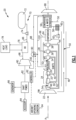
- Figure 1 schematically illustrates an example hydrogen steam injected inter-cooled turbine engine that is generally indicated at 20.
- the engine includes a turboexpander 80 where a heated cooling flow from the first heat exchanger is expanded to generate shaft power and cooled to recover thermal energy input into the cooling flow.
- the engine 20 includes core engine with a core airflow path C through a fan 22, a compressor section 24, a combustor 26 and a turbine section 28.
- the fan 22 drives inlet air as a core flow 54 into the compressor section 24.
- the core flow 54 is compressed and communicated to a combustor 26.
- the core flow 54 is mixed with a fuel flow 96 and ignited to generate a high energy gas flow 52 that expands through the turbine section 28 where energy is extracted and utilized to drive the fan 22 and the compressor section 24.
- a bypass flow 48 may flow through the fan 22 and bypass the remaining components of the engine 20.
- the high energy gas flow 52 is exhausted from the turbine section 28 and communicated through an evaporator 64 and a condenser assembly 56 before being exhausted through a nozzle 68.
- the example compressor section 24 includes a low pressure compressor (LPC) 30 and a high pressure compressor (HPC) 32.
- the turbine section 28 includes a high pressure turbine (HPT) 34, an intermediate pressure turbine (IPT) 36, and a low pressure turbine (LPT) 38.
- the turbines 34, 36 and 38 are coupled to a corresponding compressor section.
- the HPT 34 is coupled by a high shaft 40 to drive the HPT 32.
- An intermediate shaft 42 couples the IPT 36 to the LPC 30.
- a low shaft 44 is coupled between the LPT 38 and a gearbox 46 to drive the fan 22.
- the example gearbox 46 is an epicyclical gear train, such as a planetary gear system, star gear system or other known gear system, with a gear reduction ratio of greater than about 2.3.
- the engine 20 is configured to burn hydrogen provided by a fuel system 70.
- the fuel system 70 includes a liquid hydrogen (LH 2 ) tank 72 in communication with at least one pump 74.
- the pump 74 drives a fuel flow 96 to the combustor through a fuel system and eventually to the combustor 26.
- LH 2 provides a cooling flow utilized as a thermal heat sink to cool engine and/or aircraft heat loads.
- the fuel flow 96 is placed in thermal communication with a heat load 78 through a heat exchanger 76.
- the heat loads 78 may include, any engine and/or aircraft system, such as for example and without limitation, super conducting electrics, a working fluid of an environmental control system of the aircraft, an air conditioning heat exchanger, and engine working fluid heat exchangers. Heat accepted into the hydrogen fuel flow increase the overall fuel temperature prior to injection into the combustor 26.
- a turboexpander 80 is provided to recovery thermal energy input into the fuel flow 96.
- the turboexpander 80 receives a heated fuel flow 98 from the heat exchanger 76.
- the heated fuel flow 98 is expanded and cooled through the turboexpander 80.
- Expansion through the turboexpander 80 generates shaft power to drive the shaft 82.
- the shaft 82 is utilized to drive an engine accessory component 84 and/or a generator 86. It should be appreciated that the shaft 82 driven by the turboexpander 80 may be utilized to drive other engine and aircraft components within the scope and contemplation of this disclosure.
- the cooled fuel flow 100 exhausted from the turboexpander 80 is routed to the condenser assembly 56 through a cooled fuel path 88.
- the cooled fuel flow 100 from the turboexpander 80 has additional capacity to absorb heat and is utilized in the condenser assembly 56 to cool the exhaust gas flow 52 and condense water into a liquid phase.
- the cooled fuel flow 100 is heated in the process and communicated from the condenser assembly 56 to the combustor 26 as a reheated fuel flow 102.
- a valve 90 is provided such that all or a portion of the cooled fuel flow 100 may bypass the condenser assembly 56.
- a portion of the bypass airflow 50 is communicated to the condenser assembly 56 to provide a heat sink to cool the exhaust gas flow and transform water into the liquid phase.
- the bypass airflow 50 may be entirely sufficient to provide the cooling needed to liquify water from the exhaust gas flow 52.
- the additional thermal heat sink capacity provided by the cooled fuel flow 100 may not be needed and is therefore bypassed directly to the combustor 26 by the valve 90.
- a controller 92 is provided that is programmed to operate the control valve 90 depending on aircraft an engine operating conditions as schematically indicated at 94.
- the controller 92 may actuate the valve 90 to direct all or a portion of the cooled fuel flow 100 to the condenser assembly 56 to provide additional heat absorption capacity.
- the example controller 92 may be programmed to operate the valve 90 to direct the cooled fuel flow 100 to accept additional heat based on combustor operation.
- the reheated fuel flow 102 may be desired to improve combustion efficiency.
- the controller 92 may be programmed to control the valve 90 to tailor a flow of cooled fuel flow 100 from the turboexpander 80 to improve both condenser assembly and combustor operation and efficiency.
- An evaporator 64 is exposed to heat from the exhaust gas flow 52 to generate a steam flow 66 from a water flow 58 from the condenser assembly 56.
- Water recovered by the condenser assembly 56 is communicated to a water tank 60, pressurized by a pump 62 and communicated to the evaporator 64.
- the recovered water is transformed into the steam flow 66 and communicated into the core flow path C.
- the generated steam improves performance by increasing turbine mass flow and power output without additional work required by the compressor section 24.
- the steam flow is injected into the combustor 26.
- the steam flow 66 may also be injected at a location upstream of the combustor 26.
- the engine 20 has an increased power output from the injected steam 66 due to an increasing mass flow through the turbine section 32 without a corresponding increase in work from the compressor section 24.
- An example engine operation cycle may include up to (or more than) 35% steam-air-ratios (SAR) and may be assisted by a multiple fold (e.g., 2x, 3x, etc.) increase in moisture from burning H 2 as the fuel.
- SAR steam-air-ratios
- another example engine embodiment is schematically indicated at 25 and includes an additional heat exchanger 104 for accepting heat from another heat load 106.
- the cooled fuel flow 100 from the turboexpander 80 is communicated to both the condenser assembly 56 and to the heat exchanger 104.
- the heat exchanger 104 provides for cooling the heat load 106.
- the heat load 106 may be any heat generating engine or aircraft system.
- the additional heat load 106 may include a lubrication system, an electric machine, power electronics or a cooling system.
- other engine or aircraft systems may be cooled by the cooled fuel flow 100 exhausted from the turboexpander 80.
- one heat exchanger 104 is shown by way of example, several heat exchangers could be utilized and are within the contemplation and scope of this disclosure.
- Reheated flow 108 from the heat exchanger 104 is communicated to the combustor 26.
- the reheated flow 108 may be combined with the reheated flow 102 from the condenser assembly 56.
- FIG. 3 another example engine embodiment is shown and schematically indicated at 110.
- the engine 110 uses a steam flow 66 from the evaporator 64 to drive turboexpander 112.
- the steam flow 66 expands and cools through the turboexpander 112 to drive a shaft 82 and generate shaft power.
- the shaft power may be utilized to drive engine and aircraft components as disclosed.
- the cooled steam flow 120 may than be communicated directly to the combustor 26 or routed to a heat exchanger 116 to accept additional heat from a heat load 118.
- heat from the heat load 118 is transferred into the cooled steam flow 120 in a heat exchanger 116.
- a valve 114 is provided and controlled by a controller 92 to bypass and or proportion the cooled steam flow 120 between the combustor 26 and the heat exchanger 116.
- the bypass of cooled steam flow 120 may be provided based on current aircraft operating conditions 94 communicated to the controller 92.
- the further use of the cooled steam flow 120 provides for the additional reclamation of thermal energy in the form of shaft power provided by the turboexpander 112.
- example engine 20 is described and shown by way of example as other engine configurations would benefit from this disclosure and are within the contemplation and scope of this disclosure. Moreover, it will be appreciated that other engine configurations may include additional structures and features and are within the contemplation and scope of this disclosure.
- the disclosed assemblies provide for recovery of thermal energy input into a cooling flow used as a heat sink to improve engine efficiency.
Landscapes
- Engineering & Computer Science (AREA)
- Chemical & Material Sciences (AREA)
- Combustion & Propulsion (AREA)
- Mechanical Engineering (AREA)
- General Engineering & Computer Science (AREA)
- Engine Equipment That Uses Special Cycles (AREA)
Applications Claiming Priority (2)
| Application Number | Priority Date | Filing Date | Title |
|---|---|---|---|
| US202363441515P | 2023-01-27 | 2023-01-27 | |
| US18/329,044 US12180893B2 (en) | 2023-01-27 | 2023-06-05 | Hydrogen steam injected turbine engine with turboexpander heat recovery |
Publications (1)
| Publication Number | Publication Date |
|---|---|
| EP4407162A1 true EP4407162A1 (de) | 2024-07-31 |
Family
ID=89771784
Family Applications (1)
| Application Number | Title | Priority Date | Filing Date |
|---|---|---|---|
| EP24154540.9A Pending EP4407162A1 (de) | 2023-01-27 | 2024-01-29 | Wasserstoffdampfeinspritzturbinenmotor mit turboexpanderwärmerückgewinnung |
Country Status (2)
| Country | Link |
|---|---|
| US (2) | US12180893B2 (de) |
| EP (1) | EP4407162A1 (de) |
Families Citing this family (5)
| Publication number | Priority date | Publication date | Assignee | Title |
|---|---|---|---|---|
| EP4501796A1 (de) * | 2023-07-31 | 2025-02-05 | Airbus Operations, S.L.U. | Klimatisierungssystem für ein flugzeug |
| US20250059911A1 (en) * | 2023-08-17 | 2025-02-20 | General Electric Company | Turbine engine including a steam system |
| US12421895B2 (en) * | 2024-02-01 | 2025-09-23 | General Electric Company | Turbine engine including a condenser system |
| US12352207B1 (en) * | 2024-03-29 | 2025-07-08 | General Electric Company | Aircraft gas turbine engine including a steam system |
| US20250369664A1 (en) * | 2024-05-31 | 2025-12-04 | Rtx Corporation | Deicing and icing prevention system for advance cycle condensers |
Citations (4)
| Publication number | Priority date | Publication date | Assignee | Title |
|---|---|---|---|---|
| US20160123226A1 (en) * | 2014-10-30 | 2016-05-05 | Rolls-Royce Plc | Gas turbine using a cryogenic fuel and extracting work therefrom |
| US20200088102A1 (en) * | 2018-09-14 | 2020-03-19 | United Technologies Corporation | Hybrid expander cycle with intercooling and turbo-generator |
| US20210207500A1 (en) * | 2018-05-22 | 2021-07-08 | MTU Aero Engines AG | Exhaust-gas treatment device, aircraft propulsion system, and method for treating an exhaust-gas stream |
| US20220195928A1 (en) * | 2020-12-23 | 2022-06-23 | Raytheon Technologies Corporation | Gas turbine engines having cryogenic fuel systems |
Family Cites Families (18)
| Publication number | Priority date | Publication date | Assignee | Title |
|---|---|---|---|---|
| DE2413507A1 (de) * | 1974-03-20 | 1975-10-02 | Motoren Turbinen Union | Gasturbine fuer kryogenen kraftstoff |
| US5901547A (en) * | 1996-06-03 | 1999-05-11 | Air Products And Chemicals, Inc. | Operation method for integrated gasification combined cycle power generation system |
| SG104914A1 (en) * | 1997-06-30 | 2004-07-30 | Hitachi Ltd | Gas turbine |
| DE19962386A1 (de) * | 1999-12-23 | 2001-06-28 | Alstom Power Schweiz Ag Baden | Verfahren zum Nachrüsten eines Sattdampf erzeugenden Systems mit mindestens einer Dampfturbogruppe sowie nach dem Verfahren nachgerüstete Dampfkraftanlage |
| CA2891549A1 (en) * | 2012-11-30 | 2014-08-28 | General Electric Company | Dual fuel aircraft system comprising a thermostatic expansion valve |
| GB201501045D0 (en) | 2015-01-22 | 2015-03-11 | Rolls Royce Plc | Aircraft propulsion system |
| US11041439B2 (en) | 2018-09-14 | 2021-06-22 | Raytheon Technologies Corporation | Hybrid expander cycle with turbo-generator and cooled power electronics |
| DE102019203595A1 (de) * | 2019-03-15 | 2020-09-17 | MTU Aero Engines AG | Luftfahrzeug |
| US11506124B2 (en) | 2020-03-27 | 2022-11-22 | Raytheon Technologies Corporation | Supercritical CO2 cycle for gas turbine engines having supplemental cooling |
| US11448133B2 (en) * | 2020-05-05 | 2022-09-20 | Raytheon Technologies Corporation | Moderate pressure liquid hydrogen storage for hybrid-electric propulsion system |
| DE102021201629A1 (de) * | 2020-08-05 | 2022-02-10 | MTU Aero Engines AG | Abgasbehandlungsvorrichtung für ein flugtriebwerk |
| US11719156B2 (en) * | 2021-03-30 | 2023-08-08 | Doosan Enerbility Co., Ltd. | Combined power generation system with feedwater fuel preheating arrangement |
| CN114912717B (zh) | 2022-07-13 | 2022-10-25 | 成都秦川物联网科技股份有限公司 | 基于物联网的智慧城市保障住房申请风险评估方法和系统 |
| GB202212898D0 (en) * | 2022-09-05 | 2022-10-19 | Rolls Royce Plc | Component and method of manufacturing thereof |
| US12546250B2 (en) * | 2023-02-10 | 2026-02-10 | Rtx Corporation | Steam turbine bypass for increased water heat absorption capacity steam injected turbine engine |
| US20250052190A1 (en) * | 2023-08-11 | 2025-02-13 | General Electric Company | Turbine engine including a steam system |
| US12270333B2 (en) * | 2023-08-28 | 2025-04-08 | Rtx Corporation | Partial exhaust gas condensation with inverse Brayton control |
| US12264609B2 (en) * | 2023-08-29 | 2025-04-01 | Rtx Corporation | Partial exhaust gas augmented condensation |
-
2023
- 2023-06-05 US US18/329,044 patent/US12180893B2/en active Active
-
2024
- 2024-01-29 EP EP24154540.9A patent/EP4407162A1/de active Pending
- 2024-12-10 US US18/975,263 patent/US12486801B2/en active Active
Patent Citations (4)
| Publication number | Priority date | Publication date | Assignee | Title |
|---|---|---|---|---|
| US20160123226A1 (en) * | 2014-10-30 | 2016-05-05 | Rolls-Royce Plc | Gas turbine using a cryogenic fuel and extracting work therefrom |
| US20210207500A1 (en) * | 2018-05-22 | 2021-07-08 | MTU Aero Engines AG | Exhaust-gas treatment device, aircraft propulsion system, and method for treating an exhaust-gas stream |
| US20200088102A1 (en) * | 2018-09-14 | 2020-03-19 | United Technologies Corporation | Hybrid expander cycle with intercooling and turbo-generator |
| US20220195928A1 (en) * | 2020-12-23 | 2022-06-23 | Raytheon Technologies Corporation | Gas turbine engines having cryogenic fuel systems |
Also Published As
| Publication number | Publication date |
|---|---|
| US12180893B2 (en) | 2024-12-31 |
| US20240254920A1 (en) | 2024-08-01 |
| US12486801B2 (en) | 2025-12-02 |
| US20250101917A1 (en) | 2025-03-27 |
Similar Documents
| Publication | Publication Date | Title |
|---|---|---|
| EP4407162A1 (de) | Wasserstoffdampfeinspritzturbinenmotor mit turboexpanderwärmerückgewinnung | |
| EP4279720B1 (de) | Turbinenmotor mit überhitzter dampfeinspritzung | |
| EP4321744B1 (de) | Zwischengekühlte vorwärmung eines dampfeinspritzenden turbinenmotors | |
| EP4707575A2 (de) | Wasserabscheider für wasserstoffgetriebenen turbinenmotor | |
| US20250084787A1 (en) | Condenser for hydrogen steam injected turbine engine | |
| EP4279718B1 (de) | Kondensatorkanal eines wasserstoffbetriebenen turbinenmotors | |
| EP4517067A1 (de) | Zwischenkühlung durch kondensation eines teilabgasstroms | |
| US12078104B2 (en) | Hydrogen steam injected and inter-cooled turbine engine | |
| EP4414544A1 (de) | Erhöhte wasserwärmeaufnahmekapazität für turbinenmotor mit dampfeinspritzung | |
| EP4407160A1 (de) | Abwärmerückgewinnung aus leistungselektronik in einem rückgewinnungszyklus | |
| EP4279719B1 (de) | Wasserstoffdampfeinspritzturbinenmotor mit gekühlter kühlluft | |
| EP4279721B1 (de) | Wasserstoffdampfeinspritzturbinenmotor mit rückströmung | |
| US12473858B2 (en) | Partial exhaust bottoming cycle | |
| US20240360791A1 (en) | Cryo-assisted bottoming cycle heat source sequencing | |
| EP4678893A1 (de) | Kryounterstützte bottoming-zyklus-wärmequellensequenzierung | |
| US20260015969A1 (en) | Fuel cell exhaust condensation with turbomachinery water augmentation using cryogenic bottoming cycle | |
| EP4678891A2 (de) | Kryogenunterstützter bottoming-zyklus | |
| EP4678887A1 (de) | Teilkondensation von abgasen mit kryogenem unterstütztem bottoming-zyklus |
Legal Events
| Date | Code | Title | Description |
|---|---|---|---|
| PUAI | Public reference made under article 153(3) epc to a published international application that has entered the european phase |
Free format text: ORIGINAL CODE: 0009012 |
|
| STAA | Information on the status of an ep patent application or granted ep patent |
Free format text: STATUS: THE APPLICATION HAS BEEN PUBLISHED |
|
| AK | Designated contracting states |
Kind code of ref document: A1 Designated state(s): AL AT BE BG CH CY CZ DE DK EE ES FI FR GB GR HR HU IE IS IT LI LT LU LV MC ME MK MT NL NO PL PT RO RS SE SI SK SM TR |
|
| STAA | Information on the status of an ep patent application or granted ep patent |
Free format text: STATUS: REQUEST FOR EXAMINATION WAS MADE |
|
| 17P | Request for examination filed |
Effective date: 20250131 |