EP4582638A2 - Systeme zur bestimmung und vorrichtungen zur anzeige der lebensdauer von austauschbaren komponenten davon und verfahren dafür - Google Patents
Systeme zur bestimmung und vorrichtungen zur anzeige der lebensdauer von austauschbaren komponenten davon und verfahren dafür Download PDFInfo
- Publication number
- EP4582638A2 EP4582638A2 EP24217978.6A EP24217978A EP4582638A2 EP 4582638 A2 EP4582638 A2 EP 4582638A2 EP 24217978 A EP24217978 A EP 24217978A EP 4582638 A2 EP4582638 A2 EP 4582638A2
- Authority
- EP
- European Patent Office
- Prior art keywords
- injector
- component
- fluid
- replaceable
- injection
- Prior art date
- Legal status (The legal status is an assumption and is not a legal conclusion. Google has not performed a legal analysis and makes no representation as to the accuracy of the status listed.)
- Pending
Links
Images





Classifications
-
- G—PHYSICS
- G16—INFORMATION AND COMMUNICATION TECHNOLOGY [ICT] SPECIALLY ADAPTED FOR SPECIFIC APPLICATION FIELDS
- G16H—HEALTHCARE INFORMATICS, i.e. INFORMATION AND COMMUNICATION TECHNOLOGY [ICT] SPECIALLY ADAPTED FOR THE HANDLING OR PROCESSING OF MEDICAL OR HEALTHCARE DATA
- G16H20/00—ICT specially adapted for therapies or health-improving plans, e.g. for handling prescriptions, for steering therapy or for monitoring patient compliance
- G16H20/10—ICT specially adapted for therapies or health-improving plans, e.g. for handling prescriptions, for steering therapy or for monitoring patient compliance relating to drugs or medications, e.g. for ensuring correct administration to patients
- G16H20/17—ICT specially adapted for therapies or health-improving plans, e.g. for handling prescriptions, for steering therapy or for monitoring patient compliance relating to drugs or medications, e.g. for ensuring correct administration to patients delivered via infusion or injection
-
- A—HUMAN NECESSITIES
- A61—MEDICAL OR VETERINARY SCIENCE; HYGIENE
- A61M—DEVICES FOR INTRODUCING MEDIA INTO, OR ONTO, THE BODY; DEVICES FOR TRANSDUCING BODY MEDIA OR FOR TAKING MEDIA FROM THE BODY; DEVICES FOR PRODUCING OR ENDING SLEEP OR STUPOR
- A61M5/00—Devices for bringing media into the body in a subcutaneous, intra-vascular or intramuscular way; Accessories therefor, e.g. filling or cleaning devices, arm-rests
- A61M5/007—Devices for bringing media into the body in a subcutaneous, intra-vascular or intramuscular way; Accessories therefor, e.g. filling or cleaning devices, arm-rests for contrast media
-
- A—HUMAN NECESSITIES
- A61—MEDICAL OR VETERINARY SCIENCE; HYGIENE
- A61M—DEVICES FOR INTRODUCING MEDIA INTO, OR ONTO, THE BODY; DEVICES FOR TRANSDUCING BODY MEDIA OR FOR TAKING MEDIA FROM THE BODY; DEVICES FOR PRODUCING OR ENDING SLEEP OR STUPOR
- A61M5/00—Devices for bringing media into the body in a subcutaneous, intra-vascular or intramuscular way; Accessories therefor, e.g. filling or cleaning devices, arm-rests
- A61M5/14—Infusion devices, e.g. infusing by gravity; Blood infusion; Accessories therefor
- A61M5/142—Pressure infusion, e.g. using pumps
-
- A—HUMAN NECESSITIES
- A61—MEDICAL OR VETERINARY SCIENCE; HYGIENE
- A61M—DEVICES FOR INTRODUCING MEDIA INTO, OR ONTO, THE BODY; DEVICES FOR TRANSDUCING BODY MEDIA OR FOR TAKING MEDIA FROM THE BODY; DEVICES FOR PRODUCING OR ENDING SLEEP OR STUPOR
- A61M5/00—Devices for bringing media into the body in a subcutaneous, intra-vascular or intramuscular way; Accessories therefor, e.g. filling or cleaning devices, arm-rests
- A61M5/14—Infusion devices, e.g. infusing by gravity; Blood infusion; Accessories therefor
- A61M5/142—Pressure infusion, e.g. using pumps
- A61M5/145—Pressure infusion, e.g. using pumps using pressurised reservoirs, e.g. pressurised by means of pistons
-
- A—HUMAN NECESSITIES
- A61—MEDICAL OR VETERINARY SCIENCE; HYGIENE
- A61M—DEVICES FOR INTRODUCING MEDIA INTO, OR ONTO, THE BODY; DEVICES FOR TRANSDUCING BODY MEDIA OR FOR TAKING MEDIA FROM THE BODY; DEVICES FOR PRODUCING OR ENDING SLEEP OR STUPOR
- A61M5/00—Devices for bringing media into the body in a subcutaneous, intra-vascular or intramuscular way; Accessories therefor, e.g. filling or cleaning devices, arm-rests
- A61M5/14—Infusion devices, e.g. infusing by gravity; Blood infusion; Accessories therefor
- A61M5/142—Pressure infusion, e.g. using pumps
- A61M5/145—Pressure infusion, e.g. using pumps using pressurised reservoirs, e.g. pressurised by means of pistons
- A61M5/1452—Pressure infusion, e.g. using pumps using pressurised reservoirs, e.g. pressurised by means of pistons pressurised by means of pistons
-
- A—HUMAN NECESSITIES
- A61—MEDICAL OR VETERINARY SCIENCE; HYGIENE
- A61M—DEVICES FOR INTRODUCING MEDIA INTO, OR ONTO, THE BODY; DEVICES FOR TRANSDUCING BODY MEDIA OR FOR TAKING MEDIA FROM THE BODY; DEVICES FOR PRODUCING OR ENDING SLEEP OR STUPOR
- A61M5/00—Devices for bringing media into the body in a subcutaneous, intra-vascular or intramuscular way; Accessories therefor, e.g. filling or cleaning devices, arm-rests
- A61M5/14—Infusion devices, e.g. infusing by gravity; Blood infusion; Accessories therefor
- A61M5/168—Means for controlling media flow to the body or for metering media to the body, e.g. drip meters, counters ; Monitoring media flow to the body
- A61M5/16804—Flow controllers
-
- A—HUMAN NECESSITIES
- A61—MEDICAL OR VETERINARY SCIENCE; HYGIENE
- A61M—DEVICES FOR INTRODUCING MEDIA INTO, OR ONTO, THE BODY; DEVICES FOR TRANSDUCING BODY MEDIA OR FOR TAKING MEDIA FROM THE BODY; DEVICES FOR PRODUCING OR ENDING SLEEP OR STUPOR
- A61M5/00—Devices for bringing media into the body in a subcutaneous, intra-vascular or intramuscular way; Accessories therefor, e.g. filling or cleaning devices, arm-rests
- A61M5/14—Infusion devices, e.g. infusing by gravity; Blood infusion; Accessories therefor
- A61M5/168—Means for controlling media flow to the body or for metering media to the body, e.g. drip meters, counters ; Monitoring media flow to the body
- A61M5/16804—Flow controllers
- A61M5/16813—Flow controllers by controlling the degree of opening of the flow line
-
- A—HUMAN NECESSITIES
- A61—MEDICAL OR VETERINARY SCIENCE; HYGIENE
- A61M—DEVICES FOR INTRODUCING MEDIA INTO, OR ONTO, THE BODY; DEVICES FOR TRANSDUCING BODY MEDIA OR FOR TAKING MEDIA FROM THE BODY; DEVICES FOR PRODUCING OR ENDING SLEEP OR STUPOR
- A61M5/00—Devices for bringing media into the body in a subcutaneous, intra-vascular or intramuscular way; Accessories therefor, e.g. filling or cleaning devices, arm-rests
- A61M5/14—Infusion devices, e.g. infusing by gravity; Blood infusion; Accessories therefor
- A61M5/168—Means for controlling media flow to the body or for metering media to the body, e.g. drip meters, counters ; Monitoring media flow to the body
- A61M5/16831—Monitoring, detecting, signalling or eliminating infusion flow anomalies
-
- A—HUMAN NECESSITIES
- A61—MEDICAL OR VETERINARY SCIENCE; HYGIENE
- A61M—DEVICES FOR INTRODUCING MEDIA INTO, OR ONTO, THE BODY; DEVICES FOR TRANSDUCING BODY MEDIA OR FOR TAKING MEDIA FROM THE BODY; DEVICES FOR PRODUCING OR ENDING SLEEP OR STUPOR
- A61M5/00—Devices for bringing media into the body in a subcutaneous, intra-vascular or intramuscular way; Accessories therefor, e.g. filling or cleaning devices, arm-rests
- A61M5/14—Infusion devices, e.g. infusing by gravity; Blood infusion; Accessories therefor
- A61M5/168—Means for controlling media flow to the body or for metering media to the body, e.g. drip meters, counters ; Monitoring media flow to the body
- A61M5/16831—Monitoring, detecting, signalling or eliminating infusion flow anomalies
- A61M5/16854—Monitoring, detecting, signalling or eliminating infusion flow anomalies by monitoring line pressure
-
- A—HUMAN NECESSITIES
- A61—MEDICAL OR VETERINARY SCIENCE; HYGIENE
- A61M—DEVICES FOR INTRODUCING MEDIA INTO, OR ONTO, THE BODY; DEVICES FOR TRANSDUCING BODY MEDIA OR FOR TAKING MEDIA FROM THE BODY; DEVICES FOR PRODUCING OR ENDING SLEEP OR STUPOR
- A61M5/00—Devices for bringing media into the body in a subcutaneous, intra-vascular or intramuscular way; Accessories therefor, e.g. filling or cleaning devices, arm-rests
- A61M5/14—Infusion devices, e.g. infusing by gravity; Blood infusion; Accessories therefor
- A61M5/168—Means for controlling media flow to the body or for metering media to the body, e.g. drip meters, counters ; Monitoring media flow to the body
- A61M5/16877—Adjusting flow; Devices for setting a flow rate
-
- A—HUMAN NECESSITIES
- A61—MEDICAL OR VETERINARY SCIENCE; HYGIENE
- A61M—DEVICES FOR INTRODUCING MEDIA INTO, OR ONTO, THE BODY; DEVICES FOR TRANSDUCING BODY MEDIA OR FOR TAKING MEDIA FROM THE BODY; DEVICES FOR PRODUCING OR ENDING SLEEP OR STUPOR
- A61M5/00—Devices for bringing media into the body in a subcutaneous, intra-vascular or intramuscular way; Accessories therefor, e.g. filling or cleaning devices, arm-rests
- A61M5/14—Infusion devices, e.g. infusing by gravity; Blood infusion; Accessories therefor
- A61M5/168—Means for controlling media flow to the body or for metering media to the body, e.g. drip meters, counters ; Monitoring media flow to the body
- A61M5/16886—Means for controlling media flow to the body or for metering media to the body, e.g. drip meters, counters ; Monitoring media flow to the body for measuring fluid flow rate, i.e. flowmeters
-
- A—HUMAN NECESSITIES
- A61—MEDICAL OR VETERINARY SCIENCE; HYGIENE
- A61M—DEVICES FOR INTRODUCING MEDIA INTO, OR ONTO, THE BODY; DEVICES FOR TRANSDUCING BODY MEDIA OR FOR TAKING MEDIA FROM THE BODY; DEVICES FOR PRODUCING OR ENDING SLEEP OR STUPOR
- A61M5/00—Devices for bringing media into the body in a subcutaneous, intra-vascular or intramuscular way; Accessories therefor, e.g. filling or cleaning devices, arm-rests
- A61M5/14—Infusion devices, e.g. infusing by gravity; Blood infusion; Accessories therefor
- A61M5/168—Means for controlling media flow to the body or for metering media to the body, e.g. drip meters, counters ; Monitoring media flow to the body
- A61M5/172—Means for controlling media flow to the body or for metering media to the body, e.g. drip meters, counters ; Monitoring media flow to the body electrical or electronic
- A61M5/1723—Means for controlling media flow to the body or for metering media to the body, e.g. drip meters, counters ; Monitoring media flow to the body electrical or electronic using feedback of body parameters, e.g. blood-sugar, pressure
-
- G—PHYSICS
- G16—INFORMATION AND COMMUNICATION TECHNOLOGY [ICT] SPECIALLY ADAPTED FOR SPECIFIC APPLICATION FIELDS
- G16H—HEALTHCARE INFORMATICS, i.e. INFORMATION AND COMMUNICATION TECHNOLOGY [ICT] SPECIALLY ADAPTED FOR THE HANDLING OR PROCESSING OF MEDICAL OR HEALTHCARE DATA
- G16H40/00—ICT specially adapted for the management or administration of healthcare resources or facilities; ICT specially adapted for the management or operation of medical equipment or devices
- G16H40/40—ICT specially adapted for the management or administration of healthcare resources or facilities; ICT specially adapted for the management or operation of medical equipment or devices for the management of medical equipment or devices, e.g. scheduling maintenance or upgrades
-
- G—PHYSICS
- G16—INFORMATION AND COMMUNICATION TECHNOLOGY [ICT] SPECIALLY ADAPTED FOR SPECIFIC APPLICATION FIELDS
- G16H—HEALTHCARE INFORMATICS, i.e. INFORMATION AND COMMUNICATION TECHNOLOGY [ICT] SPECIALLY ADAPTED FOR THE HANDLING OR PROCESSING OF MEDICAL OR HEALTHCARE DATA
- G16H40/00—ICT specially adapted for the management or administration of healthcare resources or facilities; ICT specially adapted for the management or operation of medical equipment or devices
- G16H40/60—ICT specially adapted for the management or administration of healthcare resources or facilities; ICT specially adapted for the management or operation of medical equipment or devices for the operation of medical equipment or devices
- G16H40/63—ICT specially adapted for the management or administration of healthcare resources or facilities; ICT specially adapted for the management or operation of medical equipment or devices for the operation of medical equipment or devices for local operation
-
- A—HUMAN NECESSITIES
- A61—MEDICAL OR VETERINARY SCIENCE; HYGIENE
- A61M—DEVICES FOR INTRODUCING MEDIA INTO, OR ONTO, THE BODY; DEVICES FOR TRANSDUCING BODY MEDIA OR FOR TAKING MEDIA FROM THE BODY; DEVICES FOR PRODUCING OR ENDING SLEEP OR STUPOR
- A61M5/00—Devices for bringing media into the body in a subcutaneous, intra-vascular or intramuscular way; Accessories therefor, e.g. filling or cleaning devices, arm-rests
- A61M5/14—Infusion devices, e.g. infusing by gravity; Blood infusion; Accessories therefor
- A61M5/142—Pressure infusion, e.g. using pumps
- A61M5/14244—Pressure infusion, e.g. using pumps adapted to be carried by the patient, e.g. portable on the body
- A61M2005/14268—Pressure infusion, e.g. using pumps adapted to be carried by the patient, e.g. portable on the body with a reusable and a disposable component
-
- A—HUMAN NECESSITIES
- A61—MEDICAL OR VETERINARY SCIENCE; HYGIENE
- A61M—DEVICES FOR INTRODUCING MEDIA INTO, OR ONTO, THE BODY; DEVICES FOR TRANSDUCING BODY MEDIA OR FOR TAKING MEDIA FROM THE BODY; DEVICES FOR PRODUCING OR ENDING SLEEP OR STUPOR
- A61M5/00—Devices for bringing media into the body in a subcutaneous, intra-vascular or intramuscular way; Accessories therefor, e.g. filling or cleaning devices, arm-rests
- A61M5/14—Infusion devices, e.g. infusing by gravity; Blood infusion; Accessories therefor
- A61M5/168—Means for controlling media flow to the body or for metering media to the body, e.g. drip meters, counters ; Monitoring media flow to the body
- A61M5/172—Means for controlling media flow to the body or for metering media to the body, e.g. drip meters, counters ; Monitoring media flow to the body electrical or electronic
- A61M5/1723—Means for controlling media flow to the body or for metering media to the body, e.g. drip meters, counters ; Monitoring media flow to the body electrical or electronic using feedback of body parameters, e.g. blood-sugar, pressure
- A61M2005/1726—Means for controlling media flow to the body or for metering media to the body, e.g. drip meters, counters ; Monitoring media flow to the body electrical or electronic using feedback of body parameters, e.g. blood-sugar, pressure the body parameters being measured at, or proximate to, the infusion site
-
- A—HUMAN NECESSITIES
- A61—MEDICAL OR VETERINARY SCIENCE; HYGIENE
- A61M—DEVICES FOR INTRODUCING MEDIA INTO, OR ONTO, THE BODY; DEVICES FOR TRANSDUCING BODY MEDIA OR FOR TAKING MEDIA FROM THE BODY; DEVICES FOR PRODUCING OR ENDING SLEEP OR STUPOR
- A61M2205/00—General characteristics of the apparatus
- A61M2205/18—General characteristics of the apparatus with alarm
-
- A—HUMAN NECESSITIES
- A61—MEDICAL OR VETERINARY SCIENCE; HYGIENE
- A61M—DEVICES FOR INTRODUCING MEDIA INTO, OR ONTO, THE BODY; DEVICES FOR TRANSDUCING BODY MEDIA OR FOR TAKING MEDIA FROM THE BODY; DEVICES FOR PRODUCING OR ENDING SLEEP OR STUPOR
- A61M2205/00—General characteristics of the apparatus
- A61M2205/33—Controlling, regulating or measuring
- A61M2205/332—Force measuring means
-
- A—HUMAN NECESSITIES
- A61—MEDICAL OR VETERINARY SCIENCE; HYGIENE
- A61M—DEVICES FOR INTRODUCING MEDIA INTO, OR ONTO, THE BODY; DEVICES FOR TRANSDUCING BODY MEDIA OR FOR TAKING MEDIA FROM THE BODY; DEVICES FOR PRODUCING OR ENDING SLEEP OR STUPOR
- A61M2205/00—General characteristics of the apparatus
- A61M2205/33—Controlling, regulating or measuring
- A61M2205/3331—Pressure; Flow
-
- A—HUMAN NECESSITIES
- A61—MEDICAL OR VETERINARY SCIENCE; HYGIENE
- A61M—DEVICES FOR INTRODUCING MEDIA INTO, OR ONTO, THE BODY; DEVICES FOR TRANSDUCING BODY MEDIA OR FOR TAKING MEDIA FROM THE BODY; DEVICES FOR PRODUCING OR ENDING SLEEP OR STUPOR
- A61M2205/00—General characteristics of the apparatus
- A61M2205/33—Controlling, regulating or measuring
- A61M2205/3368—Temperature
-
- A—HUMAN NECESSITIES
- A61—MEDICAL OR VETERINARY SCIENCE; HYGIENE
- A61M—DEVICES FOR INTRODUCING MEDIA INTO, OR ONTO, THE BODY; DEVICES FOR TRANSDUCING BODY MEDIA OR FOR TAKING MEDIA FROM THE BODY; DEVICES FOR PRODUCING OR ENDING SLEEP OR STUPOR
- A61M2205/00—General characteristics of the apparatus
- A61M2205/50—General characteristics of the apparatus with microprocessors or computers
-
- A—HUMAN NECESSITIES
- A61—MEDICAL OR VETERINARY SCIENCE; HYGIENE
- A61M—DEVICES FOR INTRODUCING MEDIA INTO, OR ONTO, THE BODY; DEVICES FOR TRANSDUCING BODY MEDIA OR FOR TAKING MEDIA FROM THE BODY; DEVICES FOR PRODUCING OR ENDING SLEEP OR STUPOR
- A61M2205/00—General characteristics of the apparatus
- A61M2205/50—General characteristics of the apparatus with microprocessors or computers
- A61M2205/502—User interfaces, e.g. screens or keyboards
-
- A—HUMAN NECESSITIES
- A61—MEDICAL OR VETERINARY SCIENCE; HYGIENE
- A61M—DEVICES FOR INTRODUCING MEDIA INTO, OR ONTO, THE BODY; DEVICES FOR TRANSDUCING BODY MEDIA OR FOR TAKING MEDIA FROM THE BODY; DEVICES FOR PRODUCING OR ENDING SLEEP OR STUPOR
- A61M2205/00—General characteristics of the apparatus
- A61M2205/58—Means for facilitating use, e.g. by people with impaired vision
- A61M2205/581—Means for facilitating use, e.g. by people with impaired vision by audible feedback
-
- A—HUMAN NECESSITIES
- A61—MEDICAL OR VETERINARY SCIENCE; HYGIENE
- A61M—DEVICES FOR INTRODUCING MEDIA INTO, OR ONTO, THE BODY; DEVICES FOR TRANSDUCING BODY MEDIA OR FOR TAKING MEDIA FROM THE BODY; DEVICES FOR PRODUCING OR ENDING SLEEP OR STUPOR
- A61M2205/00—General characteristics of the apparatus
- A61M2205/58—Means for facilitating use, e.g. by people with impaired vision
- A61M2205/583—Means for facilitating use, e.g. by people with impaired vision by visual feedback
-
- A—HUMAN NECESSITIES
- A61—MEDICAL OR VETERINARY SCIENCE; HYGIENE
- A61M—DEVICES FOR INTRODUCING MEDIA INTO, OR ONTO, THE BODY; DEVICES FOR TRANSDUCING BODY MEDIA OR FOR TAKING MEDIA FROM THE BODY; DEVICES FOR PRODUCING OR ENDING SLEEP OR STUPOR
- A61M2205/00—General characteristics of the apparatus
- A61M2205/58—Means for facilitating use, e.g. by people with impaired vision
- A61M2205/583—Means for facilitating use, e.g. by people with impaired vision by visual feedback
- A61M2205/584—Means for facilitating use, e.g. by people with impaired vision by visual feedback having a color code
-
- A—HUMAN NECESSITIES
- A61—MEDICAL OR VETERINARY SCIENCE; HYGIENE
- A61M—DEVICES FOR INTRODUCING MEDIA INTO, OR ONTO, THE BODY; DEVICES FOR TRANSDUCING BODY MEDIA OR FOR TAKING MEDIA FROM THE BODY; DEVICES FOR PRODUCING OR ENDING SLEEP OR STUPOR
- A61M2205/00—General characteristics of the apparatus
- A61M2205/70—General characteristics of the apparatus with testing or calibration facilities
- A61M2205/702—General characteristics of the apparatus with testing or calibration facilities automatically during use
-
- G—PHYSICS
- G06—COMPUTING OR CALCULATING; COUNTING
- G06Q—INFORMATION AND COMMUNICATION TECHNOLOGY [ICT] SPECIALLY ADAPTED FOR ADMINISTRATIVE, COMMERCIAL, FINANCIAL, MANAGERIAL OR SUPERVISORY PURPOSES; SYSTEMS OR METHODS SPECIALLY ADAPTED FOR ADMINISTRATIVE, COMMERCIAL, FINANCIAL, MANAGERIAL OR SUPERVISORY PURPOSES, NOT OTHERWISE PROVIDED FOR
- G06Q10/00—Administration; Management
- G06Q10/20—Administration of product repair or maintenance
Definitions
- a medical practitioner places a catheter or needle into a vein or artery of the patient.
- the catheter or needle is connected to a manual or an automatic fluid injector system by way of tubing and a connector that interfaces with the fluid injector system.
- Automatic fluid injector systems typically include at least one syringe connected to at least one fluid injector having, for example, a powered linear piston.
- the at least one syringe includes, for example, a source of contrast and/or a source of flushing fluid
- injection parameter settings settings into an electronic control system of the fluid injector for a fixed volume of contrast and/or saline and a fixed rate of injection.
- the fluid delivery system can also be integrated with other injector control systems to prevent the injector from performing an injection at forces, pressures, and flow rates exceeding those which the replaceable injector component can withstand, based on the replaceable injector component's remaining or unused viable life and any identified accumulated distress.
- injector from performing an injection at forces, pressures, and flow rates exceeding those which the replaceable injector component can withstand, based on the replaceable injector component's remaining or unused viable life and any identified accumulated distress.
- manufacturing and design requirements for the replaceable injector components can be reduced since injector forces can be more accurately matched to maximum levels that the replaceable injector component can withstand.
- reusable components need not be manufactured to withstand maximum injector forces for the entire lifespan of the reusable component, as is currently required.
- a method of monitoring a status of a replaceable component of a fluid injector includes: providing a viable life for a replaceable component of a fluid injector; calculating an accumulated amount of distress experienced by the replaceable component based on each set of previously collected injection parameter data associated with each injection procedure previously performed on one or more patients therewith; determining, based in part on the accumulated amount of distress, a used portion of the viable life that the replaceable component has experienced as a result of the previously performed injection procedures and, therewith, an unused portion of the viable life; and providing to an operator of the fluid injector an indication of at least one of the unused and used portions of the viable life of the replaceable component.
- the injection parameter data can include one or more of an injection pressure, an injection time, and an injection temperature.
- the accumulated amount of distress can be calculated using at least an algorithm that employs a model descriptive of material degradation of the replaceable component.
- the model can be based, for example, on Miner's Rule or on an Inverse Power Law-Weibull Model.
- the injection parameter data can include data collected from multiple portions of the fluid injector.
- providing to the operator of the fluid injector an indication of the unused and/or used portions of the viable life can include displaying a visual representation of the used portion of the viable life relative to the viable life of the replaceable component. The viable life of the replaceable component can be determined before the replaceable component is installed on the fluid injector.
- the at least one replaceable component comprises a disposable multi-patient fluid path set.
- the fluid delivery system can include a sensing or timing device associated with a portion of the fluid injector and configured to collect the injection parameter data.
- a system for monitoring a replaceable component of an apparatus includes: a controller for controlling operation of an apparatus being monitored by the system and programming instructions operably associated with the controller.
- the programming instructions when executed, cause the controller to: accept input of a viable life for a replaceable component of the apparatus; calculate an accumulated amount of distress experienced by the replaceable component based on each set of previously collected use data associated with each previous use of the replaceable component by the apparatus; and determine, based in part on the accumulated amount of distress, a used portion of the viable life that the replaceable component has experienced as a result of the previous use or uses thereof and an unused portion of the viable life.
- the system also includes a visual and/or audio feedback device configured to provide to an operator of the apparatus an indication of at least one of the unused and used portions of the viable life of the replaceable component.
- a method of monitoring a status of a replaceable component of a fluid injector includes: providing a viable life for the replaceable component; collecting a present set of injection parameter data associated with a planned injection procedure to be performed with the replaceable component; calculating an estimated amount of distress that would be experienced by the replaceable component if the planned injection procedure were to be performed in accordance with the present set of injection parameter data; determining, based in part on the estimated amount of distress, a portion of the viable life that would be experienced by the replaceable component if the planned injection procedure were to be performed and, as a result, the replaceable component were to incur the estimated amount of distress; comparing the viable life of the replaceable component to the portion of the viable life that would be experienced by the replaceable component if the planned injection procedure were to be performed; and providing an indication of a result of the comparison to an operator of the fluid injector.
- the injection parameter data can include one or more of an injection pressure, an injection time, and an injection temperature.
- the estimated amount of distress can be calculated using at least an algorithm that employs a model descriptive of material degradation of the replaceable component.
- the model can be based, for example, on Miner's Rule or on an Inverse Power Law-Weibull Model.
- the injection parameter data can include data collected from multiple portions of the fluid injector.
- providing an indication of a result of the comparison can include displaying a visual representation of the used portion of the viable life relative to the viable life of the replaceable component. The viable life of the replaceable component can be determined before the replaceable component is installed on the fluid injector.
- a method of monitoring a status of a replaceable component of a fluid injector includes: providing a viable life for the replaceable component; calculating an accumulated amount of distress experienced by the replaceable component based on each set of previously collected injection parameter data associated with each injection procedure previously performed therewith; collecting a present set of injection parameter data associated with a planned injection procedure to be performed with the replaceable component; calculating an estimated amount of additional distress that would be experienced by the replaceable component if the planned injection procedure were to be performed in accordance with the present set of injection parameter data; determining, based in part on the accumulated amount of distress, a used portion of the viable life that the replaceable component has experienced as a result of the previously performed injection procedures and, therewith, an unused portion of the viable life; determining, based in part on the estimated amount of additional distress, an additional portion of the viable life that would be experienced by the replaceable component if the planned injection procedure were to be performed and, as a result, the replaceable component were to incur the estimated amount of additional distress
- the injection parameter data can include one or more of an injection pressure, an injection time, and an injection temperature.
- the estimated and the accumulated amounts of distress can each be calculated using at least an algorithm that employs a model descriptive of material degradation of the replaceable component.
- the model can be based, for example, on Miner's Rule or on an Inverse Power Law-Weibull Model.
- the injection parameter data can include data collected from multiple portions of the fluid injector.
- the disposable life indicator also includes a check valve disposed between the fluid set of the fluid injector and the fluid collecting portion.
- the check valve can be configured to permit fluid flow above a threshold pressure to access the fluid collecting portion.
- the check valve can be a one-way check valve.
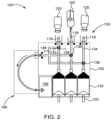
- the MUDS 130 can include one or more valves 136, such as stopcock valves, for controlling which medical fluid or combinations of medical fluids are withdrawn from the multi-dose bulk fluid source 120 and/or are delivered to a patient through each syringe 132.
- one or more valves 136 can be provided either on the syringe 132 or on a manifold 148.
- the manifold 148 can be in fluid communication via valves 136 and/or syringes 132 with a first end of the MUDS fluid path 134 that connects each syringe 132 to the corresponding bulk fluid source 120.
- the opposing second end of the MUDS fluid path 134 can be connected to the respective bulk fluid connector 118 that is configured for fluidly connecting with the bulk fluid source 120.
- a disposable life indicator 50 which can be associated with, connected to, or integrally formed with a portion of the replaceable component, such as the MUDS fluid path 134, will now be discussed in detail.
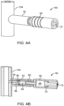
- the disposable life indicator 50 can be attached to a port 52 extending from the fluid path 134 and in fluid communication with the fluid path 134 through a narrow channel 54 (shown in FIGS. 3B and 4B ).
- the port 52 can include any suitable connector, as is known in the art, for connecting the indicator 50 to the fluid path 134 including, but not limited to, a luer connector, a snap fit connector, threaded connectors, or combinations thereof.
- the retainer 60 such as an insert or housing, includes a hollow cylindrical portion for receiving the gauge 62 of the life indicator 50, and is positioned adjacent to and/or pressed against the check valve 56.
- a flow restrictor 64 is inserted in a proximal end of the retainer 60.
- the flow restrictor 64 is provided to disrupt high pressure fluid flows from entering the gauge 62 of the indictor 50 to prevent distress to the gauge 62 from fluid flowing through the check valve 56.
- the flow restrictor 64 can be a porous filter with a plurality of tortuous flow passages. Directing fluid through the tortuous passages reduces flow rate as the fluid advances towards the gauge 62.
- the gauge 62 is at least partially received in the retainer 60 and extends from a distal end thereof.
- the gauge 62 includes a fluid collecting portion 66 at a proximal end thereof, and a movable indicating structure, such as the piston 70, which is slideably received within the barrel/bore of the gauge 62.
- the piston 70 advances through the barrel of the gauge 62 as fluid collects in the fluid collecting portion 66.
- the piston 70 can have a conspicuous end-of-use portion 72, such as a colored tip, that is configured to extend from the barrel of the gauge 62 and thus is easily visible when the maximum cumulative pressure is reached and/or exceeded.
- the gauge 62 can include various graduations or markings (not shown in FIGS.
- markings can indicate to the injector operator an estimated number of injections remaining before the replaceable component must be replaced, an estimated total number of injections performed already, or other relevant information.
- the gauge 62 can be an electronic volume sensor configured to measure fluid collected in the fluid collecting portion 66 of the gauge 62. A signal from the volume sensor can be sent to a controller or user interface of the injector for providing data to the operator regarding cumulative pressure level.
- the gauge 62 can include an electronic indicator.
- the gauge 62 can include a light, such as an LED bulb, configured to light up when the piston 70 reaches its end-of-use position.
- the electronic indicator or LED bulb can be located on the life indicator 50, on the fluid injector 100, or at a remote location.
- graduations or markings on the gauge 62 barrel can include electronic indicators, such as LED bulbs, configured to light up when the piston 70 reaches a particular position within the gauge 62.
- the electronic indicator can be a verbal or audio indicator, such as an alarm that sounds when the piston 70 advances to the end-of-use position and should be replaced.
- a small volume of fluid is diverted into the narrow channel 54 of the port 52 and toward the gauge 62. If the fluid flow is sufficient to open the one-way check valve 56, fluid passes through the valve 56 and into the retainer 60. The fluid is prevented from flowing back into the MUDS fluid path 134 by the valve 56. After passing through the valve 56, the fluid is directed though the flow restrictor 64 and into the fluid collecting portion 66 of the gauge 62. As the volume of collected fluid increases, the piston 70 is driven through barrel of the gauge 62, thereby providing a cumulative indication of pressure exerted on the replaceable or disposable injector component.
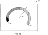
- the gauge is a bourdon tube arrangement 74.
- the bourdon tube arrangement 74 which resembles a standard gas gauge for a gasoline powered vehicle, includes a flexible tube 76 and an arm 78 driven by a pinion 80 and biasing spring 82.
- the pinion 80 and biasing spring 82 are pivotally engaged to the tube 76.
- a proximal end of the tube 76 is connected to and receives pressurized fluid from the MUDS fluid path 134 through the narrow channel 54 of the port 52.
- the tube 76 exerts a force on the pinion 80 and biasing spring 82 causing the arm 78 to transition from the unused or full position to the empty or end-of-life position.
- a stop 84 located adjacent to the proximal end of the tube 76 indicates when the reusable component reaches the end of its expected life.
- the indicator 50 can include other electronic or mechanical mechanisms or devices or gauges, as are known in the art, for indicating that fluid is being collected from the fluid path 134.
- the mechanism can be an inflatable balloon. As the injector is in use, fluid collects in the balloon. The balloon is permitted to continue to expand until a particular size or inflation level is obtained, which signifies end-of-use for the replaceable component.
- a coiled balloon or tube such as a party horn, can be configured to unfurl as fluid collects therein. The horn can be configured such that when the horn portion is fully uncurled, the replaceable component has reached the end of its useful life and should be replaced.
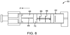
- the elastic member 85 can only slightly bias the piston or plunger 70 so that the piston or plunger 70 freely advances through the gauge 62.
- the indicator 50 may not include any anchor or stretchable component at all for the piston or plunger 70, as shown, for example, in FIG. 7 .
- the elastic member 85 can be more resistant to deformation, meaning that more force must be applied by pressurized fluid before the piston or plunger 70 advances.
- the gauge 62 can include translucent or transparent portions so that the injector operator can see how far the piston or plunger 70 has advanced.
- the piston or plunger 70 can also be a bright color so that it is easily identified by the injector operator.
- Markings 86 such as graduations, can be provided on the gauge 62. The markings 86 can be used to indicate how much time (e.g., number of injection cycles) are left until the piston or plunger 70 reaches the end-of-use position indicating that the replaceable component needs to be replaced.
- the disposable life indicator 50 can be replaced with an electronic sensor for measuring the fluid pressure (e.g., a maximum or average fluid pressure) for each injection performed using the replaceable injector component.
- a high pressure sensor can be connected to the port 52 and placed in fluid communication with the MUDS fluid path 134.
- the pressure sensor can determine fluid pressure for fluid flowing through the MUDS fluid path 134.
- the pressure sensor can include a wired connection or a wireless transmitter, such as a short range data transmitter using BLUETOOTH ® , for sending a signal from the sensor to a controller or user interface device.
- the controller or user interface device can provide information, such as the measured pressure of the injection and information about the unused viable life of the injector component to the system operator.
- a suitable pressure sensor that can be connected to the MUDS fluid path 134 and used to determine lifespan for replaceable injector components is disclosed in United States Patent Application No. 13/798,709 to Riley et al. , which published as Publication No. 2013/0255390 (hereinafter "the '390 publication), and which is incorporated by reference herein in its entirety.
- the measurements recorded by the high pressure sensor can be used to calculate the unused viable life for replaceable components of the injector.
- the collected measurements and calculated lifespan information can be presented to the user or system operator through a user interface, such as an audio or visual display.
- the injector component is formed from a chromogenic plastic configured to change color or tint over time when exposed to a chemical, such as saline or contrast, or from lack of exposure to oxygen.
- a chemical such as saline or contrast
- the color or tint of the plastic material of the injector component changes a small amount each time that injection fluid is passed through the injector component.
- the system operator can observe the injector component prior to performing an injection. If the system operator determines that the injector component has changed color a sufficient degree, the operator replaces the component with a new one.
- the injector can include optical sensors configured to automatically identify a color change in an injector component. When a sufficient color change is identified, the injector can instruct the operator to replace the injector component.
- the monitoring system 10 with automated and/or electronic components for monitoring and providing feedback about the status of replaceable components will now be discussed in detail.
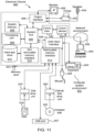
- the controller 12 includes a processor 16 with electronic circuitry capable of performing calculations according to instructions stored on computer readable memory 18 associated with the processor 16 or provided to the processor 16 from some external source.
- the processor 16 can also issue instructions and/or requests for information to other electronic devices, such as sensors, remote electronic databases, data sources, or to the injector 100 for controlling operation thereof.
- the controller 12 can be integrated with the injector 100 and, for example, can be configured to perform some or all of the functions of the electronic control device that controls operation of the injector 100.
- the controller 12 can also be a remote device such as a dedicated electronic device, portable computer, or tablet PC. In that case, the controller 12 can include either a wired connection to the injector 100 or a wireless antenna/transceiver 20 for sending data and instructions between the injector 100 and controller 12.
- the monitoring system 10 can also include biological sensors 26, such as conductivity sensors, electrochemical sensors, ion sensors, and the like, configured to identify contamination in fluid.
- the biological sensors 26 are in fluid communication with the replaceable injector components.
- the biological sensors 26 can be positioned in one of the fluid reservoirs or in the fluid path set of the MUDS 130.
- the biological sensors 26 can be configured to provide periodic measurements of fluid quality. If contamination is identified, an alert can be provided to the system operator with the feedback device 14.
- the injector 10 can be configured not to perform an injection until the contamination alert is addressed.
- the controller 12 is configured to monitor or track the remaining or unused viable life of replaceable injector components, such as the MUDS 130, based on one or more predictive disposable life algorithms.
- the algorithm can be stored on the computer readable memory 18 associated with the controller or provided to the controller 12 from an external source.
- the algorithms estimate or determine the amount of stress/strain forces (referred to herein as "the accumulated distress") that the replaceable injector component has been subjected to and, based on an estimate of the viable life of the replaceable component (i.e., an estimate of the total amount of stress/strain forces that the replaceable component can withstand before failure), provides an estimate of remaining or unused viable life (i.e., an unused portion of the viable life).
- the algorithm is based on one or more models for demonstrating material degradation of a structure.
- the disposable predictive life algorithm can be based on Miner's Rule, which estimates that there is a linear relationship between the number of cycles ( e.g., the number of times a force is applied to an object) and the stress applied during each cycle.
- n i is the number of cycles and S i is the stress amount for each cycle.
- W Failure is the total amount of stress that the system can withstand prior to failure.
- C is the fraction of life consumed by the exposure to the n i stress cycles.
- the controller 12 can obtain these experimental values for the replaceable injector component from a lookup table or computer database.
- Other non-linear models such as an inverse power Law-Weibull model, can also be used for purposes of determining cumulative distress and unused viable life for the replaceable injector components.
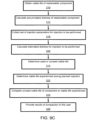
- the controller 12 can be configured to perform the following actions or steps to calculate used and/or unused viable life of a replaceable component and for providing the calculated information to a user.
- the results could include a simple message to the user indicating either that the injection can be performed (e.g., an indication that the injector is ready for injection) or that the component should be replaced prior to performing the injection.
- the results can include detailed numerical results, including the estimated distress experienced during the injection, unused viable life of the replaceable component, and/or estimated time or number of injections until the component should be replaced.
- the system can provide an audible alarm informing the user that the replaceable component is not suitable for a planned injection.
- the controller 12 can be configured to prevent an injection from begin performed if the unused viable life of the component is not sufficient for the planned injection.
Landscapes
- Health & Medical Sciences (AREA)
- Engineering & Computer Science (AREA)
- Biomedical Technology (AREA)
- Public Health (AREA)
- General Health & Medical Sciences (AREA)
- Veterinary Medicine (AREA)
- Vascular Medicine (AREA)
- Anesthesiology (AREA)
- Heart & Thoracic Surgery (AREA)
- Hematology (AREA)
- Life Sciences & Earth Sciences (AREA)
- Animal Behavior & Ethology (AREA)
- General Business, Economics & Management (AREA)
- Business, Economics & Management (AREA)
- Epidemiology (AREA)
- Medical Informatics (AREA)
- Primary Health Care (AREA)
- Diabetes (AREA)
- Chemical & Material Sciences (AREA)
- Bioinformatics & Cheminformatics (AREA)
- Medicinal Chemistry (AREA)
- Physics & Mathematics (AREA)
- Fluid Mechanics (AREA)
- Infusion, Injection, And Reservoir Apparatuses (AREA)
- Medical Treatment And Welfare Office Work (AREA)
- Management, Administration, Business Operations System, And Electronic Commerce (AREA)
- Length Measuring Devices With Unspecified Measuring Means (AREA)
- Fixing For Electrophotography (AREA)
- Control Of Metal Rolling (AREA)
Applications Claiming Priority (3)
| Application Number | Priority Date | Filing Date | Title |
|---|---|---|---|
| US201562204879P | 2015-08-13 | 2015-08-13 | |
| EP16835924.8A EP3335167B1 (de) | 2015-08-13 | 2016-08-11 | Systeme zur bestimmung und vorrichtungen zur anzeige der lebensdauer von austauschbaren komponenten davon und verfahren dafür |
| PCT/US2016/046587 WO2017027724A1 (en) | 2015-08-13 | 2016-08-11 | Systems for determining, and devices for indicating, viable life of replaceable components thereof and methods therefor |
Related Parent Applications (3)
| Application Number | Title | Priority Date | Filing Date |
|---|---|---|---|
| PCT/US2016/046587 Previously-Filed-Application WO2017027724A1 (en) | 2015-08-13 | 2016-08-11 | Systems for determining, and devices for indicating, viable life of replaceable components thereof and methods therefor |
| EP16835924.8A Division-Into EP3335167B1 (de) | 2015-08-13 | 2016-08-11 | Systeme zur bestimmung und vorrichtungen zur anzeige der lebensdauer von austauschbaren komponenten davon und verfahren dafür |
| EP16835924.8A Division EP3335167B1 (de) | 2015-08-13 | 2016-08-11 | Systeme zur bestimmung und vorrichtungen zur anzeige der lebensdauer von austauschbaren komponenten davon und verfahren dafür |
Publications (2)
| Publication Number | Publication Date |
|---|---|
| EP4582638A2 true EP4582638A2 (de) | 2025-07-09 |
| EP4582638A3 EP4582638A3 (de) | 2025-07-30 |
Family
ID=57984020
Family Applications (2)
| Application Number | Title | Priority Date | Filing Date |
|---|---|---|---|
| EP24217978.6A Pending EP4582638A3 (de) | 2015-08-13 | 2016-08-11 | Systeme zur bestimmung und vorrichtungen zur anzeige der lebensdauer von austauschbaren komponenten davon und verfahren dafür |
| EP16835924.8A Active EP3335167B1 (de) | 2015-08-13 | 2016-08-11 | Systeme zur bestimmung und vorrichtungen zur anzeige der lebensdauer von austauschbaren komponenten davon und verfahren dafür |
Family Applications After (1)
| Application Number | Title | Priority Date | Filing Date |
|---|---|---|---|
| EP16835924.8A Active EP3335167B1 (de) | 2015-08-13 | 2016-08-11 | Systeme zur bestimmung und vorrichtungen zur anzeige der lebensdauer von austauschbaren komponenten davon und verfahren dafür |
Country Status (8)
| Country | Link |
|---|---|
| US (2) | US10522250B2 (de) |
| EP (2) | EP4582638A3 (de) |
| JP (3) | JP6855444B2 (de) |
| CN (3) | CN113908373B (de) |
| AU (3) | AU2016304995B2 (de) |
| CA (1) | CA2995398C (de) |
| ES (1) | ES3024283T3 (de) |
| WO (1) | WO2017027724A1 (de) |
Families Citing this family (40)
| Publication number | Priority date | Publication date | Assignee | Title |
|---|---|---|---|---|
| ATE480278T1 (de) | 2005-09-12 | 2010-09-15 | Unomedical As | Einfürungssystem für ein infusionsset mit einem ersten und zweiten federeinheit |
| CA2792138A1 (en) | 2010-03-30 | 2011-10-06 | Unomedical A/S | Medical device |
| US10194938B2 (en) | 2011-03-14 | 2019-02-05 | UnoMedical, AS | Inserter system with transport protection |
| EP2583715A1 (de) | 2011-10-19 | 2013-04-24 | Unomedical A/S | Infusionsschlauchsystem und Herstellungsverfahren |
| US10042964B2 (en) * | 2015-03-02 | 2018-08-07 | General Electric Company | Method of evaluating a part |
| EP4582638A3 (de) * | 2015-08-13 | 2025-07-30 | Bayer HealthCare LLC | Systeme zur bestimmung und vorrichtungen zur anzeige der lebensdauer von austauschbaren komponenten davon und verfahren dafür |
| WO2017125817A1 (en) | 2016-01-19 | 2017-07-27 | Unomedical A/S | Cannula and infusion devices |
| AU2018317866B2 (en) * | 2017-08-18 | 2024-06-13 | Bayer Healthcare Llc | System, method, and computer program product for predictive maintenance |
| AU2019330795B2 (en) * | 2018-08-28 | 2025-02-06 | Bayer Healthcare Llc | Utilizing pressure measurements to detect reuse of patient lines |
| CA3141608A1 (en) | 2019-05-20 | 2020-11-26 | Unomedical A/S | Rotatable infusion device and methods thereof |
| EP3758157B1 (de) | 2019-06-27 | 2024-12-25 | Erbe Elektromedizin GmbH | Gerät mit serviceschnittstelle und verfahren zur wartung des geräts |
| WO2021016070A1 (en) * | 2019-07-19 | 2021-01-28 | Madorra Inc. | Ultrasound device with attachable components |
| CN114787936A (zh) * | 2019-11-21 | 2022-07-22 | 拜耳医药保健有限责任公司 | 用于智能流体注入器性能监测的系统、方法和计算机程序产品 |
| CN121154972A (zh) * | 2020-04-29 | 2025-12-19 | 贝克顿·迪金森公司 | 用于捕获医疗状况管理事件的图像的系统、装置和方法 |
| US20240210330A1 (en) * | 2020-05-08 | 2024-06-27 | Raspect Intelligent Inspection Limited | Systems and methods for artificial intelligence powered inspections and predictive analyses |
| CN116471981A (zh) * | 2020-09-29 | 2023-07-21 | 因柯利尔疗法公司 | 蛛网膜下流体管理方法和系统 |
| US12329930B2 (en) | 2020-09-29 | 2025-06-17 | Enclear Therapies, Inc. | Subarachnoid fluid management method and system |
| CN116528924A (zh) | 2020-10-06 | 2023-08-01 | 拜耳医药保健有限责任公司 | 用于提供对流体注入系统的访问的系统、方法和计算机程序产品 |
| US20220139541A1 (en) * | 2020-11-03 | 2022-05-05 | Koninklijke Philips N.V. | Part replacement registration tool |
| CN113221286B (zh) * | 2021-05-24 | 2022-08-19 | 北京航空航天大学 | 一种基于加速寿命试验的盘轴螺纹连接器振动可靠性评估方法 |
| US12440289B2 (en) | 2022-08-01 | 2025-10-14 | Imperative Care, Inc. | Method of priming an interventional device assembly |
| US12564414B2 (en) | 2022-08-01 | 2026-03-03 | Imperative Care, Inc. | Method of supra-aortic access for a neurovascular procedure |
| US12564458B2 (en) | 2022-08-01 | 2026-03-03 | Imperative Care, Inc. | Method of robotically driving a multi catheter assembly above the aortic arch |
| US12419703B2 (en) | 2022-08-01 | 2025-09-23 | Imperative Care, Inc. | Robotic drive system for achieving supra-aortic access |
| US20230048388A1 (en) | 2021-08-12 | 2023-02-16 | Imperative Care, Inc. | Robotically driven interventional device |
| US12446979B2 (en) | 2022-08-01 | 2025-10-21 | Imperative Care, Inc. | Method of performing a multi catheter robotic neurovascular procedure |
| US12447317B2 (en) | 2022-08-01 | 2025-10-21 | Imperative Care, Inc. | Method of priming concentrically stacked interventional devices |
| US20250285751A1 (en) | 2022-04-29 | 2025-09-11 | Bayer Healthcare Llc | Systems, Method, And Computer Program Product For Implementing A Remote Console For Use In Diagnostic Imaging Procedures |
| CN114949651B (zh) * | 2022-07-01 | 2023-03-14 | 山西新华防化装备研究院有限公司 | 机械式一次性使用指示结构 |
| US20240041480A1 (en) | 2022-08-02 | 2024-02-08 | Imperative Care, Inc. | Multi catheter system with integrated fluidics management |
| CN116127660B (zh) * | 2022-11-18 | 2023-12-15 | 智城数创(西安)科技有限公司 | 一种基于gis的智慧管网智能综合管理平台 |
| CN120529878A (zh) | 2022-12-01 | 2025-08-22 | 因普瑞缇夫护理公司 | 伸缩驱动台及使用方法 |
| JP2026500623A (ja) | 2022-12-01 | 2026-01-08 | インペラティブ ケア インコーポレイテッド | ロボットカテーテル駆動システムのための座屈防止デバイス |
| CN120916725A (zh) | 2022-12-01 | 2025-11-07 | 因普瑞缇夫护理公司 | 用于机器人化导管驱动系统的控制器 |
| WO2024134532A1 (en) * | 2022-12-20 | 2024-06-27 | Karia Deval | System and method for delivery monitoring and occlusion detection in an infusion pump |
| AU2024229140A1 (en) | 2023-03-01 | 2025-08-07 | Bayer Healthcare Llc | System, method, and computer program product for medical device event management |
| US12377206B2 (en) | 2023-05-17 | 2025-08-05 | Imperative Care, Inc. | Fluidics control system for multi catheter stack |
| WO2024249670A2 (en) | 2023-05-31 | 2024-12-05 | Imperative Care, Inc. | Magnetic coupling through a sterile field barrier |
| USD1102447S1 (en) | 2023-11-30 | 2025-11-18 | Imperative Care, Inc. | Display screen or portion thereof with graphical user interface |
| USD1119865S1 (en) | 2023-11-30 | 2026-03-24 | Imperative Care, Inc. | Controller |
Citations (1)
| Publication number | Priority date | Publication date | Assignee | Title |
|---|---|---|---|---|
| US20130255390A1 (en) | 2012-04-03 | 2013-10-03 | Medrad, Inc. | High pressure sensor for use with a fluid delivery system |
Family Cites Families (35)
| Publication number | Priority date | Publication date | Assignee | Title |
|---|---|---|---|---|
| US3977391A (en) * | 1974-07-16 | 1976-08-31 | Hittman Corporation | Pressure sensor apparatus |
| US5138845A (en) * | 1991-04-09 | 1992-08-18 | Brdg-Tndr Corporation | Method and apparatus for controlling the flow of process fluids |
| JPH0762505B2 (ja) * | 1991-05-08 | 1995-07-05 | 小熊機械株式会社 | 弁の開度指示装置 |
| US7766873B2 (en) * | 1998-10-29 | 2010-08-03 | Medtronic Minimed, Inc. | Method and apparatus for detecting occlusions in an ambulatory infusion pump |
| US6626862B1 (en) * | 2000-04-04 | 2003-09-30 | Acist Medical Systems, Inc. | Fluid management and component detection system |
| JP2002058968A (ja) * | 2000-08-18 | 2002-02-26 | Suehiro Tadashi | 濾過装置 |
| JP4306195B2 (ja) * | 2002-07-12 | 2009-07-29 | 泉工医科工業株式会社 | 薬液注入装置 |
| US7270648B2 (en) * | 2002-12-23 | 2007-09-18 | Farhad Kazemzadeh | Drug delivery apparatus |
| NO320468B1 (no) * | 2003-10-17 | 2005-12-12 | Nat Oilwell Norway As | System for overvakning og administrasjon av vedlikehold av utstyrskomponenter |
| US7216019B2 (en) * | 2004-07-08 | 2007-05-08 | Celerity, Inc. | Method and system for a mass flow controller with reduced pressure sensitivity |
| WO2006059597A1 (ja) * | 2004-11-30 | 2006-06-08 | Nemoto Kyorindo Co., Ltd. | 機械システム |
| DE102004063650B4 (de) * | 2004-12-31 | 2022-10-20 | Ypsomed Ag | Lebensdaueranzeige für eine Vorrichtung zur dosierten Verabreichung eines Produkts |
| US7775966B2 (en) | 2005-02-24 | 2010-08-17 | Ethicon Endo-Surgery, Inc. | Non-invasive pressure measurement in a fluid adjustable restrictive device |
| ES2370994T3 (es) * | 2005-04-04 | 2011-12-26 | Palmerton, Christopher A. | Sistema de evacuación de fluido con filtro de comunicación bidireccional. |
| KR101458416B1 (ko) * | 2005-11-21 | 2014-11-07 | 어시스트 메디칼 시스템즈, 인크. | 의료용 유체 주입 시스템 |
| JP2011509757A (ja) | 2008-01-18 | 2011-03-31 | マリンクロッド・インコーポレイテッド | システムの摩耗と使用に基づく自動較正を有する医療流体注入器 |
| EP3260145B1 (de) * | 2008-04-09 | 2019-12-11 | Roche Diabetes Care GmbH | Fluidstandsensor für ein modulares, haut getragenes system zur flüssigkeitsabgabe |
| WO2010015953A2 (en) * | 2008-08-04 | 2010-02-11 | Koninklijke Philips Electronics N.V. | Spectral imaging |
| CN102202705A (zh) * | 2008-10-31 | 2011-09-28 | 马林克罗特公司 | 多剂量注射系统 |
| US9370621B2 (en) * | 2008-12-16 | 2016-06-21 | Medtronic Minimed, Inc. | Needle insertion systems and methods |
| WO2010117922A1 (en) * | 2009-04-08 | 2010-10-14 | Mallinckrodt Inc. | Multi-dose medical fluid injection system having patient-specific tubing set with use indicator |
| US8383044B2 (en) * | 2009-07-09 | 2013-02-26 | Becton, Dickinson And Company | Blood sampling device |
| CA2760057C (en) * | 2009-09-29 | 2018-01-09 | Mallinckrodt Llc | Systems and method for assessing functionality of dual check valve arrangements in medical tubing sets |
| TWM396695U (en) * | 2010-07-23 | 2011-01-21 | Univ China Medical | Modified liquid trap cup and a liquid trap assembly |
| US10737014B2 (en) * | 2010-11-09 | 2020-08-11 | Femasys Inc. | Methods and devices for managing fluid pressure |
| EP2658590A1 (de) * | 2010-12-29 | 2013-11-06 | Novo Nordisk A/S | Vorrichtung zur injektion anpassbarer dosierungen eines flüssigwirkstoffs |
| KR101064390B1 (ko) * | 2011-03-03 | 2011-09-14 | 강원대학교산학협력단 | 주입기용 부품의 마모 시험 장치 |
| BR112014004530A2 (pt) * | 2011-09-02 | 2017-03-28 | Unitract Syringe Pty Ltd | mecanismo de acionamento para bombas de administração de fármaco com indicação de estado integrada |
| JP5409751B2 (ja) * | 2011-11-29 | 2014-02-05 | 株式会社沖データ | 交換部材管理方法、電子装置の交換部材管理方法、電子装置、画像形成装置及び交換部材管理システム |
| TW201427904A (zh) * | 2012-08-29 | 2014-07-16 | Brita Professional Gmbh & Co Kg | 藉由操作液體處理系統而獲致處理資料之方法 |
| CN103880116B (zh) * | 2012-12-19 | 2016-04-13 | 上海风享环保科技有限公司 | 一种可更换滤芯的饮用水滤水壶 |
| US20160045841A1 (en) * | 2013-03-15 | 2016-02-18 | Transtar Group, Ltd. | New and improved system for processing various chemicals and materials |
| US10549084B2 (en) * | 2014-01-10 | 2020-02-04 | Bayer Healthcare Llc | Single-use disposable set connector |
| US9821123B2 (en) * | 2014-01-27 | 2017-11-21 | Ucb Biopharma Sprl | Auto-injector |
| EP4582638A3 (de) * | 2015-08-13 | 2025-07-30 | Bayer HealthCare LLC | Systeme zur bestimmung und vorrichtungen zur anzeige der lebensdauer von austauschbaren komponenten davon und verfahren dafür |
-
2016
- 2016-08-11 EP EP24217978.6A patent/EP4582638A3/de active Pending
- 2016-08-11 ES ES16835924T patent/ES3024283T3/es active Active
- 2016-08-11 JP JP2018506977A patent/JP6855444B2/ja active Active
- 2016-08-11 CA CA2995398A patent/CA2995398C/en active Active
- 2016-08-11 EP EP16835924.8A patent/EP3335167B1/de active Active
- 2016-08-11 CN CN202111085752.9A patent/CN113908373B/zh active Active
- 2016-08-11 AU AU2016304995A patent/AU2016304995B2/en active Active
- 2016-08-11 CN CN201680052310.5A patent/CN108027901B/zh active Active
- 2016-08-11 WO PCT/US2016/046587 patent/WO2017027724A1/en not_active Ceased
- 2016-08-11 US US15/750,878 patent/US10522250B2/en active Active
- 2016-08-11 CN CN202111085735.5A patent/CN113908372B/zh active Active
-
2019
- 2019-12-10 US US16/708,763 patent/US10783993B2/en active Active
-
2021
- 2021-03-10 JP JP2021038251A patent/JP6917532B2/ja not_active Expired - Fee Related
- 2021-03-16 JP JP2021042291A patent/JP6975354B2/ja active Active
- 2021-09-23 AU AU2021236509A patent/AU2021236509B2/en active Active
- 2021-09-23 AU AU2021236508A patent/AU2021236508B2/en not_active Ceased
Patent Citations (1)
| Publication number | Priority date | Publication date | Assignee | Title |
|---|---|---|---|---|
| US20130255390A1 (en) | 2012-04-03 | 2013-10-03 | Medrad, Inc. | High pressure sensor for use with a fluid delivery system |
Also Published As
| Publication number | Publication date |
|---|---|
| US10783993B2 (en) | 2020-09-22 |
| CA2995398C (en) | 2024-01-02 |
| JP6975354B2 (ja) | 2021-12-01 |
| US10522250B2 (en) | 2019-12-31 |
| JP2021099872A (ja) | 2021-07-01 |
| JP6855444B2 (ja) | 2021-04-07 |
| US20200118676A1 (en) | 2020-04-16 |
| EP3335167A4 (de) | 2019-07-03 |
| AU2021236509A1 (en) | 2021-10-21 |
| CN113908372A (zh) | 2022-01-11 |
| US20180240548A1 (en) | 2018-08-23 |
| JP2021087875A (ja) | 2021-06-10 |
| AU2021236509B2 (en) | 2023-04-06 |
| JP2018530814A (ja) | 2018-10-18 |
| CN113908373A (zh) | 2022-01-11 |
| CN113908373B (zh) | 2023-05-09 |
| AU2016304995B2 (en) | 2021-10-21 |
| EP3335167B1 (de) | 2025-02-12 |
| AU2021236508B2 (en) | 2023-03-02 |
| CN108027901A (zh) | 2018-05-11 |
| JP6917532B2 (ja) | 2021-08-11 |
| EP4582638A3 (de) | 2025-07-30 |
| CN113908372B (zh) | 2023-09-01 |
| AU2016304995A1 (en) | 2018-02-22 |
| CN108027901B (zh) | 2022-03-01 |
| EP3335167A1 (de) | 2018-06-20 |
| ES3024283T3 (en) | 2025-06-04 |
| AU2021236508A1 (en) | 2021-10-28 |
| CA2995398A1 (en) | 2017-02-16 |
| WO2017027724A1 (en) | 2017-02-16 |
Similar Documents
| Publication | Publication Date | Title |
|---|---|---|
| AU2021236508B2 (en) | Systems for determining, and devices for indicating, viable life of replaceable components thereof and methods therefor | |
| US9814833B2 (en) | Pressure based refill status monitor for implantable pumps | |
| ES2799305T3 (es) | Adaptador inteligente para dispositivos de infusión | |
| JP2017529149A (ja) | 注入異常の検出 | |
| WO2010144533A1 (en) | Controlled delivery of substances system and method | |
| KR20150056592A (ko) | 인슐린 주입 펌프 명령의 혈당 영향을 표시하는 방법 및 시스템 | |
| US20260102562A1 (en) | Systems and methods for occlusion detection in infusion pumps | |
| JP2024501977A (ja) | 輸液装置におけるバッテリ警報を生成するためのシステムおよび方法 | |
| CN112638461A (zh) | 利用压力测量来检测患者管线的重复使用 | |
| HK40050278B (en) | Utilizing pressure measurements to detect reuse of patient lines |
Legal Events
| Date | Code | Title | Description |
|---|---|---|---|
| PUAI | Public reference made under article 153(3) epc to a published international application that has entered the european phase |
Free format text: ORIGINAL CODE: 0009012 |
|
| STAA | Information on the status of an ep patent application or granted ep patent |
Free format text: STATUS: THE APPLICATION HAS BEEN PUBLISHED |
|
| REG | Reference to a national code |
Ref country code: DE Ref legal event code: R079 Free format text: PREVIOUS MAIN CLASS: E02F0009220000 Ipc: G16H0040400000 |
|
| PUAL | Search report despatched |
Free format text: ORIGINAL CODE: 0009013 |
|
| AC | Divisional application: reference to earlier application |
Ref document number: 3335167 Country of ref document: EP Kind code of ref document: P |
|
| AK | Designated contracting states |
Kind code of ref document: A2 Designated state(s): AL AT BE BG CH CY CZ DE DK EE ES FI FR GB GR HR HU IE IS IT LI LT LU LV MC MK MT NL NO PL PT RO RS SE SI SK SM TR |
|
| AK | Designated contracting states |
Kind code of ref document: A3 Designated state(s): AL AT BE BG CH CY CZ DE DK EE ES FI FR GB GR HR HU IE IS IT LI LT LU LV MC MK MT NL NO PL PT RO RS SE SI SK SM TR |
|
| RIC1 | Information provided on ipc code assigned before grant |
Ipc: G16H 40/40 20180101AFI20250626BHEP Ipc: G16H 40/63 20180101ALI20250626BHEP Ipc: G06Q 10/00 20230101ALI20250626BHEP Ipc: B65D 35/56 20060101ALI20250626BHEP Ipc: B65D 83/00 20060101ALI20250626BHEP Ipc: B67D 7/06 20100101ALI20250626BHEP Ipc: B67D 7/10 20100101ALI20250626BHEP Ipc: E02F 3/43 20060101ALI20250626BHEP Ipc: E02F 9/22 20060101ALI20250626BHEP Ipc: G16H 20/17 20180101ALN20250626BHEP |
|
| STAA | Information on the status of an ep patent application or granted ep patent |
Free format text: STATUS: REQUEST FOR EXAMINATION WAS MADE |
|
| 17P | Request for examination filed |
Effective date: 20260130 |
|
| STAA | Information on the status of an ep patent application or granted ep patent |
Free format text: STATUS: EXAMINATION IS IN PROGRESS |