EP4582279A2 - Steckbares hybridelektrofahrzeug - Google Patents
Steckbares hybridelektrofahrzeug Download PDFInfo
- Publication number
- EP4582279A2 EP4582279A2 EP24218278.0A EP24218278A EP4582279A2 EP 4582279 A2 EP4582279 A2 EP 4582279A2 EP 24218278 A EP24218278 A EP 24218278A EP 4582279 A2 EP4582279 A2 EP 4582279A2
- Authority
- EP
- European Patent Office
- Prior art keywords
- vehicle
- battery
- plug
- disposed
- hybrid electric
- Prior art date
- Legal status (The legal status is an assumption and is not a legal conclusion. Google has not performed a legal analysis and makes no representation as to the accuracy of the status listed.)
- Pending
Links
Images
Classifications
-
- B—PERFORMING OPERATIONS; TRANSPORTING
- B60—VEHICLES IN GENERAL
- B60K—ARRANGEMENT OR MOUNTING OF PROPULSION UNITS OR OF TRANSMISSIONS IN VEHICLES; ARRANGEMENT OR MOUNTING OF PLURAL DIVERSE PRIME-MOVERS IN VEHICLES; AUXILIARY DRIVES FOR VEHICLES; INSTRUMENTATION OR DASHBOARDS FOR VEHICLES; ARRANGEMENTS IN CONNECTION WITH COOLING, AIR INTAKE, GAS EXHAUST OR FUEL SUPPLY OF PROPULSION UNITS IN VEHICLES
- B60K15/00—Arrangement in connection with fuel supply of combustion engines or other fuel consuming energy converters, e.g. fuel cells; Mounting or construction of fuel tanks
- B60K15/03—Fuel tanks
- B60K15/04—Tank inlets
-
- B—PERFORMING OPERATIONS; TRANSPORTING
- B60—VEHICLES IN GENERAL
- B60K—ARRANGEMENT OR MOUNTING OF PROPULSION UNITS OR OF TRANSMISSIONS IN VEHICLES; ARRANGEMENT OR MOUNTING OF PLURAL DIVERSE PRIME-MOVERS IN VEHICLES; AUXILIARY DRIVES FOR VEHICLES; INSTRUMENTATION OR DASHBOARDS FOR VEHICLES; ARRANGEMENTS IN CONNECTION WITH COOLING, AIR INTAKE, GAS EXHAUST OR FUEL SUPPLY OF PROPULSION UNITS IN VEHICLES
- B60K6/00—Arrangement or mounting of plural diverse prime-movers for mutual or common propulsion, e.g. hybrid propulsion systems comprising electric motors and internal combustion engines
- B60K6/20—Arrangement or mounting of plural diverse prime-movers for mutual or common propulsion, e.g. hybrid propulsion systems comprising electric motors and internal combustion engines the prime-movers consisting of electric motors and internal combustion engines, e.g. HEVs
- B60K6/22—Arrangement or mounting of plural diverse prime-movers for mutual or common propulsion, e.g. hybrid propulsion systems comprising electric motors and internal combustion engines the prime-movers consisting of electric motors and internal combustion engines, e.g. HEVs characterised by apparatus, components or means specially adapted for HEVs
- B60K6/40—Arrangement or mounting of plural diverse prime-movers for mutual or common propulsion, e.g. hybrid propulsion systems comprising electric motors and internal combustion engines the prime-movers consisting of electric motors and internal combustion engines, e.g. HEVs characterised by apparatus, components or means specially adapted for HEVs characterised by the assembly or relative disposition of components
-
- B—PERFORMING OPERATIONS; TRANSPORTING
- B60—VEHICLES IN GENERAL
- B60J—WINDOWS, WINDSCREENS, NON-FIXED ROOFS, DOORS, OR SIMILAR DEVICES FOR VEHICLES; REMOVABLE EXTERNAL PROTECTIVE COVERINGS SPECIALLY ADAPTED FOR VEHICLES
- B60J5/00—Doors
- B60J5/04—Doors arranged at the vehicle sides
- B60J5/06—Doors arranged at the vehicle sides slidable; foldable
-
- B—PERFORMING OPERATIONS; TRANSPORTING
- B60—VEHICLES IN GENERAL
- B60K—ARRANGEMENT OR MOUNTING OF PROPULSION UNITS OR OF TRANSMISSIONS IN VEHICLES; ARRANGEMENT OR MOUNTING OF PLURAL DIVERSE PRIME-MOVERS IN VEHICLES; AUXILIARY DRIVES FOR VEHICLES; INSTRUMENTATION OR DASHBOARDS FOR VEHICLES; ARRANGEMENTS IN CONNECTION WITH COOLING, AIR INTAKE, GAS EXHAUST OR FUEL SUPPLY OF PROPULSION UNITS IN VEHICLES
- B60K1/00—Arrangement or mounting of electrical propulsion units
- B60K1/04—Arrangement or mounting of electrical propulsion units of the electric storage means for propulsion
-
- B—PERFORMING OPERATIONS; TRANSPORTING
- B60—VEHICLES IN GENERAL
- B60K—ARRANGEMENT OR MOUNTING OF PROPULSION UNITS OR OF TRANSMISSIONS IN VEHICLES; ARRANGEMENT OR MOUNTING OF PLURAL DIVERSE PRIME-MOVERS IN VEHICLES; AUXILIARY DRIVES FOR VEHICLES; INSTRUMENTATION OR DASHBOARDS FOR VEHICLES; ARRANGEMENTS IN CONNECTION WITH COOLING, AIR INTAKE, GAS EXHAUST OR FUEL SUPPLY OF PROPULSION UNITS IN VEHICLES
- B60K13/00—Arrangement in connection with combustion air intake or gas exhaust of propulsion units
- B60K13/04—Arrangement in connection with combustion air intake or gas exhaust of propulsion units concerning exhaust
-
- B—PERFORMING OPERATIONS; TRANSPORTING
- B60—VEHICLES IN GENERAL
- B60K—ARRANGEMENT OR MOUNTING OF PROPULSION UNITS OR OF TRANSMISSIONS IN VEHICLES; ARRANGEMENT OR MOUNTING OF PLURAL DIVERSE PRIME-MOVERS IN VEHICLES; AUXILIARY DRIVES FOR VEHICLES; INSTRUMENTATION OR DASHBOARDS FOR VEHICLES; ARRANGEMENTS IN CONNECTION WITH COOLING, AIR INTAKE, GAS EXHAUST OR FUEL SUPPLY OF PROPULSION UNITS IN VEHICLES
- B60K15/00—Arrangement in connection with fuel supply of combustion engines or other fuel consuming energy converters, e.g. fuel cells; Mounting or construction of fuel tanks
- B60K15/03—Fuel tanks
- B60K15/063—Arrangement of tanks
-
- B—PERFORMING OPERATIONS; TRANSPORTING
- B60—VEHICLES IN GENERAL
- B60K—ARRANGEMENT OR MOUNTING OF PROPULSION UNITS OR OF TRANSMISSIONS IN VEHICLES; ARRANGEMENT OR MOUNTING OF PLURAL DIVERSE PRIME-MOVERS IN VEHICLES; AUXILIARY DRIVES FOR VEHICLES; INSTRUMENTATION OR DASHBOARDS FOR VEHICLES; ARRANGEMENTS IN CONNECTION WITH COOLING, AIR INTAKE, GAS EXHAUST OR FUEL SUPPLY OF PROPULSION UNITS IN VEHICLES
- B60K6/00—Arrangement or mounting of plural diverse prime-movers for mutual or common propulsion, e.g. hybrid propulsion systems comprising electric motors and internal combustion engines
- B60K6/20—Arrangement or mounting of plural diverse prime-movers for mutual or common propulsion, e.g. hybrid propulsion systems comprising electric motors and internal combustion engines the prime-movers consisting of electric motors and internal combustion engines, e.g. HEVs
- B60K6/22—Arrangement or mounting of plural diverse prime-movers for mutual or common propulsion, e.g. hybrid propulsion systems comprising electric motors and internal combustion engines the prime-movers consisting of electric motors and internal combustion engines, e.g. HEVs characterised by apparatus, components or means specially adapted for HEVs
- B60K6/24—Arrangement or mounting of plural diverse prime-movers for mutual or common propulsion, e.g. hybrid propulsion systems comprising electric motors and internal combustion engines the prime-movers consisting of electric motors and internal combustion engines, e.g. HEVs characterised by apparatus, components or means specially adapted for HEVs characterised by the combustion engines
-
- B—PERFORMING OPERATIONS; TRANSPORTING
- B60—VEHICLES IN GENERAL
- B60K—ARRANGEMENT OR MOUNTING OF PROPULSION UNITS OR OF TRANSMISSIONS IN VEHICLES; ARRANGEMENT OR MOUNTING OF PLURAL DIVERSE PRIME-MOVERS IN VEHICLES; AUXILIARY DRIVES FOR VEHICLES; INSTRUMENTATION OR DASHBOARDS FOR VEHICLES; ARRANGEMENTS IN CONNECTION WITH COOLING, AIR INTAKE, GAS EXHAUST OR FUEL SUPPLY OF PROPULSION UNITS IN VEHICLES
- B60K6/00—Arrangement or mounting of plural diverse prime-movers for mutual or common propulsion, e.g. hybrid propulsion systems comprising electric motors and internal combustion engines
- B60K6/20—Arrangement or mounting of plural diverse prime-movers for mutual or common propulsion, e.g. hybrid propulsion systems comprising electric motors and internal combustion engines the prime-movers consisting of electric motors and internal combustion engines, e.g. HEVs
- B60K6/22—Arrangement or mounting of plural diverse prime-movers for mutual or common propulsion, e.g. hybrid propulsion systems comprising electric motors and internal combustion engines the prime-movers consisting of electric motors and internal combustion engines, e.g. HEVs characterised by apparatus, components or means specially adapted for HEVs
- B60K6/26—Arrangement or mounting of plural diverse prime-movers for mutual or common propulsion, e.g. hybrid propulsion systems comprising electric motors and internal combustion engines the prime-movers consisting of electric motors and internal combustion engines, e.g. HEVs characterised by apparatus, components or means specially adapted for HEVs characterised by the motors or the generators
-
- B—PERFORMING OPERATIONS; TRANSPORTING
- B60—VEHICLES IN GENERAL
- B60K—ARRANGEMENT OR MOUNTING OF PROPULSION UNITS OR OF TRANSMISSIONS IN VEHICLES; ARRANGEMENT OR MOUNTING OF PLURAL DIVERSE PRIME-MOVERS IN VEHICLES; AUXILIARY DRIVES FOR VEHICLES; INSTRUMENTATION OR DASHBOARDS FOR VEHICLES; ARRANGEMENTS IN CONNECTION WITH COOLING, AIR INTAKE, GAS EXHAUST OR FUEL SUPPLY OF PROPULSION UNITS IN VEHICLES
- B60K6/00—Arrangement or mounting of plural diverse prime-movers for mutual or common propulsion, e.g. hybrid propulsion systems comprising electric motors and internal combustion engines
- B60K6/20—Arrangement or mounting of plural diverse prime-movers for mutual or common propulsion, e.g. hybrid propulsion systems comprising electric motors and internal combustion engines the prime-movers consisting of electric motors and internal combustion engines, e.g. HEVs
- B60K6/22—Arrangement or mounting of plural diverse prime-movers for mutual or common propulsion, e.g. hybrid propulsion systems comprising electric motors and internal combustion engines the prime-movers consisting of electric motors and internal combustion engines, e.g. HEVs characterised by apparatus, components or means specially adapted for HEVs
- B60K6/28—Arrangement or mounting of plural diverse prime-movers for mutual or common propulsion, e.g. hybrid propulsion systems comprising electric motors and internal combustion engines the prime-movers consisting of electric motors and internal combustion engines, e.g. HEVs characterised by apparatus, components or means specially adapted for HEVs characterised by the electric energy storing means, e.g. batteries or capacitors
-
- B—PERFORMING OPERATIONS; TRANSPORTING
- B60—VEHICLES IN GENERAL
- B60K—ARRANGEMENT OR MOUNTING OF PROPULSION UNITS OR OF TRANSMISSIONS IN VEHICLES; ARRANGEMENT OR MOUNTING OF PLURAL DIVERSE PRIME-MOVERS IN VEHICLES; AUXILIARY DRIVES FOR VEHICLES; INSTRUMENTATION OR DASHBOARDS FOR VEHICLES; ARRANGEMENTS IN CONNECTION WITH COOLING, AIR INTAKE, GAS EXHAUST OR FUEL SUPPLY OF PROPULSION UNITS IN VEHICLES
- B60K6/00—Arrangement or mounting of plural diverse prime-movers for mutual or common propulsion, e.g. hybrid propulsion systems comprising electric motors and internal combustion engines
- B60K6/20—Arrangement or mounting of plural diverse prime-movers for mutual or common propulsion, e.g. hybrid propulsion systems comprising electric motors and internal combustion engines the prime-movers consisting of electric motors and internal combustion engines, e.g. HEVs
- B60K6/50—Architecture of the driveline characterised by arrangement or kind of transmission units
-
- B—PERFORMING OPERATIONS; TRANSPORTING
- B60—VEHICLES IN GENERAL
- B60L—PROPULSION OF ELECTRICALLY-PROPELLED VEHICLES; SUPPLYING ELECTRIC POWER FOR AUXILIARY EQUIPMENT OF ELECTRICALLY-PROPELLED VEHICLES; ELECTRODYNAMIC BRAKE SYSTEMS FOR VEHICLES IN GENERAL; MAGNETIC SUSPENSION OR LEVITATION FOR VEHICLES; MONITORING OPERATING VARIABLES OF ELECTRICALLY-PROPELLED VEHICLES; ELECTRIC SAFETY DEVICES FOR ELECTRICALLY-PROPELLED VEHICLES
- B60L53/00—Methods of charging batteries, specially adapted for electric vehicles; Charging stations or on-board charging equipment therefor; Exchange of energy storage elements in electric vehicles
- B60L53/10—Methods of charging batteries, specially adapted for electric vehicles; Charging stations or on-board charging equipment therefor; Exchange of energy storage elements in electric vehicles characterised by the energy transfer between the charging station and the vehicle
- B60L53/14—Conductive energy transfer
-
- B—PERFORMING OPERATIONS; TRANSPORTING
- B60—VEHICLES IN GENERAL
- B60L—PROPULSION OF ELECTRICALLY-PROPELLED VEHICLES; SUPPLYING ELECTRIC POWER FOR AUXILIARY EQUIPMENT OF ELECTRICALLY-PROPELLED VEHICLES; ELECTRODYNAMIC BRAKE SYSTEMS FOR VEHICLES IN GENERAL; MAGNETIC SUSPENSION OR LEVITATION FOR VEHICLES; MONITORING OPERATING VARIABLES OF ELECTRICALLY-PROPELLED VEHICLES; ELECTRIC SAFETY DEVICES FOR ELECTRICALLY-PROPELLED VEHICLES
- B60L53/00—Methods of charging batteries, specially adapted for electric vehicles; Charging stations or on-board charging equipment therefor; Exchange of energy storage elements in electric vehicles
- B60L53/10—Methods of charging batteries, specially adapted for electric vehicles; Charging stations or on-board charging equipment therefor; Exchange of energy storage elements in electric vehicles characterised by the energy transfer between the charging station and the vehicle
- B60L53/14—Conductive energy transfer
- B60L53/16—Connectors, e.g. plugs or sockets, specially adapted for charging electric vehicles
-
- B—PERFORMING OPERATIONS; TRANSPORTING
- B60—VEHICLES IN GENERAL
- B60L—PROPULSION OF ELECTRICALLY-PROPELLED VEHICLES; SUPPLYING ELECTRIC POWER FOR AUXILIARY EQUIPMENT OF ELECTRICALLY-PROPELLED VEHICLES; ELECTRODYNAMIC BRAKE SYSTEMS FOR VEHICLES IN GENERAL; MAGNETIC SUSPENSION OR LEVITATION FOR VEHICLES; MONITORING OPERATING VARIABLES OF ELECTRICALLY-PROPELLED VEHICLES; ELECTRIC SAFETY DEVICES FOR ELECTRICALLY-PROPELLED VEHICLES
- B60L53/00—Methods of charging batteries, specially adapted for electric vehicles; Charging stations or on-board charging equipment therefor; Exchange of energy storage elements in electric vehicles
- B60L53/10—Methods of charging batteries, specially adapted for electric vehicles; Charging stations or on-board charging equipment therefor; Exchange of energy storage elements in electric vehicles characterised by the energy transfer between the charging station and the vehicle
- B60L53/14—Conductive energy transfer
- B60L53/18—Cables specially adapted for charging electric vehicles
-
- B—PERFORMING OPERATIONS; TRANSPORTING
- B60—VEHICLES IN GENERAL
- B60L—PROPULSION OF ELECTRICALLY-PROPELLED VEHICLES; SUPPLYING ELECTRIC POWER FOR AUXILIARY EQUIPMENT OF ELECTRICALLY-PROPELLED VEHICLES; ELECTRODYNAMIC BRAKE SYSTEMS FOR VEHICLES IN GENERAL; MAGNETIC SUSPENSION OR LEVITATION FOR VEHICLES; MONITORING OPERATING VARIABLES OF ELECTRICALLY-PROPELLED VEHICLES; ELECTRIC SAFETY DEVICES FOR ELECTRICALLY-PROPELLED VEHICLES
- B60L53/00—Methods of charging batteries, specially adapted for electric vehicles; Charging stations or on-board charging equipment therefor; Exchange of energy storage elements in electric vehicles
- B60L53/20—Methods of charging batteries, specially adapted for electric vehicles; Charging stations or on-board charging equipment therefor; Exchange of energy storage elements in electric vehicles characterised by converters located in the vehicle
- B60L53/22—Constructional details or arrangements of charging converters specially adapted for charging electric vehicles
-
- B—PERFORMING OPERATIONS; TRANSPORTING
- B60—VEHICLES IN GENERAL
- B60N—SEATS SPECIALLY ADAPTED FOR VEHICLES; VEHICLE PASSENGER ACCOMMODATION NOT OTHERWISE PROVIDED FOR
- B60N2/00—Seats specially adapted for vehicles; Arrangement or mounting of seats in vehicles
- B60N2/005—Arrangement or mounting of seats in vehicles, e.g. dismountable auxiliary seats
-
- B—PERFORMING OPERATIONS; TRANSPORTING
- B60—VEHICLES IN GENERAL
- B60N—SEATS SPECIALLY ADAPTED FOR VEHICLES; VEHICLE PASSENGER ACCOMMODATION NOT OTHERWISE PROVIDED FOR
- B60N2/00—Seats specially adapted for vehicles; Arrangement or mounting of seats in vehicles
- B60N2/005—Arrangement or mounting of seats in vehicles, e.g. dismountable auxiliary seats
- B60N2/01—Arrangement of seats relative to one another
-
- B—PERFORMING OPERATIONS; TRANSPORTING
- B60—VEHICLES IN GENERAL
- B60N—SEATS SPECIALLY ADAPTED FOR VEHICLES; VEHICLE PASSENGER ACCOMMODATION NOT OTHERWISE PROVIDED FOR
- B60N2/00—Seats specially adapted for vehicles; Arrangement or mounting of seats in vehicles
- B60N2/02—Seats specially adapted for vehicles; Arrangement or mounting of seats in vehicles the seat or part thereof being movable, e.g. adjustable
- B60N2/04—Seats specially adapted for vehicles; Arrangement or mounting of seats in vehicles the seat or part thereof being movable, e.g. adjustable the whole seat being movable
- B60N2/06—Seats specially adapted for vehicles; Arrangement or mounting of seats in vehicles the seat or part thereof being movable, e.g. adjustable the whole seat being movable slidable
-
- B—PERFORMING OPERATIONS; TRANSPORTING
- B60—VEHICLES IN GENERAL
- B60R—VEHICLES, VEHICLE FITTINGS, OR VEHICLE PARTS, NOT OTHERWISE PROVIDED FOR
- B60R16/00—Electric or fluid circuits specially adapted for vehicles and not otherwise provided for; Arrangement of elements of electric or fluid circuits specially adapted for vehicles and not otherwise provided for
- B60R16/02—Electric or fluid circuits specially adapted for vehicles and not otherwise provided for; Arrangement of elements of electric or fluid circuits specially adapted for vehicles and not otherwise provided for electric constitutive elements
- B60R16/0207—Wire harnesses
- B60R16/0215—Protecting, fastening and routing means therefor
-
- B—PERFORMING OPERATIONS; TRANSPORTING
- B60—VEHICLES IN GENERAL
- B60R—VEHICLES, VEHICLE FITTINGS, OR VEHICLE PARTS, NOT OTHERWISE PROVIDED FOR
- B60R16/00—Electric or fluid circuits specially adapted for vehicles and not otherwise provided for; Arrangement of elements of electric or fluid circuits specially adapted for vehicles and not otherwise provided for
- B60R16/02—Electric or fluid circuits specially adapted for vehicles and not otherwise provided for; Arrangement of elements of electric or fluid circuits specially adapted for vehicles and not otherwise provided for electric constitutive elements
- B60R16/023—Electric or fluid circuits specially adapted for vehicles and not otherwise provided for; Arrangement of elements of electric or fluid circuits specially adapted for vehicles and not otherwise provided for electric constitutive elements for transmission of signals between vehicle parts or subsystems
- B60R16/0239—Electronic boxes
-
- F—MECHANICAL ENGINEERING; LIGHTING; HEATING; WEAPONS; BLASTING
- F01—MACHINES OR ENGINES IN GENERAL; ENGINE PLANTS IN GENERAL; STEAM ENGINES
- F01N—GAS-FLOW SILENCERS OR EXHAUST APPARATUS FOR MACHINES OR ENGINES IN GENERAL; GAS-FLOW SILENCERS OR EXHAUST APPARATUS FOR INTERNAL-COMBUSTION ENGINES
- F01N13/00—Exhaust or silencing apparatus characterised by constructional features
- F01N13/007—Apparatus used as intake or exhaust silencer
-
- B—PERFORMING OPERATIONS; TRANSPORTING
- B60—VEHICLES IN GENERAL
- B60K—ARRANGEMENT OR MOUNTING OF PROPULSION UNITS OR OF TRANSMISSIONS IN VEHICLES; ARRANGEMENT OR MOUNTING OF PLURAL DIVERSE PRIME-MOVERS IN VEHICLES; AUXILIARY DRIVES FOR VEHICLES; INSTRUMENTATION OR DASHBOARDS FOR VEHICLES; ARRANGEMENTS IN CONNECTION WITH COOLING, AIR INTAKE, GAS EXHAUST OR FUEL SUPPLY OF PROPULSION UNITS IN VEHICLES
- B60K1/00—Arrangement or mounting of electrical propulsion units
- B60K1/04—Arrangement or mounting of electrical propulsion units of the electric storage means for propulsion
- B60K2001/0405—Arrangement or mounting of electrical propulsion units of the electric storage means for propulsion characterised by their position
- B60K2001/0422—Arrangement under the front seats
-
- B—PERFORMING OPERATIONS; TRANSPORTING
- B60—VEHICLES IN GENERAL
- B60K—ARRANGEMENT OR MOUNTING OF PROPULSION UNITS OR OF TRANSMISSIONS IN VEHICLES; ARRANGEMENT OR MOUNTING OF PLURAL DIVERSE PRIME-MOVERS IN VEHICLES; AUXILIARY DRIVES FOR VEHICLES; INSTRUMENTATION OR DASHBOARDS FOR VEHICLES; ARRANGEMENTS IN CONNECTION WITH COOLING, AIR INTAKE, GAS EXHAUST OR FUEL SUPPLY OF PROPULSION UNITS IN VEHICLES
- B60K1/00—Arrangement or mounting of electrical propulsion units
- B60K1/04—Arrangement or mounting of electrical propulsion units of the electric storage means for propulsion
- B60K2001/0405—Arrangement or mounting of electrical propulsion units of the electric storage means for propulsion characterised by their position
- B60K2001/0438—Arrangement under the floor
-
- B—PERFORMING OPERATIONS; TRANSPORTING
- B60—VEHICLES IN GENERAL
- B60K—ARRANGEMENT OR MOUNTING OF PROPULSION UNITS OR OF TRANSMISSIONS IN VEHICLES; ARRANGEMENT OR MOUNTING OF PLURAL DIVERSE PRIME-MOVERS IN VEHICLES; AUXILIARY DRIVES FOR VEHICLES; INSTRUMENTATION OR DASHBOARDS FOR VEHICLES; ARRANGEMENTS IN CONNECTION WITH COOLING, AIR INTAKE, GAS EXHAUST OR FUEL SUPPLY OF PROPULSION UNITS IN VEHICLES
- B60K15/00—Arrangement in connection with fuel supply of combustion engines or other fuel consuming energy converters, e.g. fuel cells; Mounting or construction of fuel tanks
- B60K15/03—Fuel tanks
- B60K15/063—Arrangement of tanks
- B60K2015/0633—Arrangement of tanks the fuel tank is arranged below the rear seat
-
- B—PERFORMING OPERATIONS; TRANSPORTING
- B60—VEHICLES IN GENERAL
- B60K—ARRANGEMENT OR MOUNTING OF PROPULSION UNITS OR OF TRANSMISSIONS IN VEHICLES; ARRANGEMENT OR MOUNTING OF PLURAL DIVERSE PRIME-MOVERS IN VEHICLES; AUXILIARY DRIVES FOR VEHICLES; INSTRUMENTATION OR DASHBOARDS FOR VEHICLES; ARRANGEMENTS IN CONNECTION WITH COOLING, AIR INTAKE, GAS EXHAUST OR FUEL SUPPLY OF PROPULSION UNITS IN VEHICLES
- B60K15/00—Arrangement in connection with fuel supply of combustion engines or other fuel consuming energy converters, e.g. fuel cells; Mounting or construction of fuel tanks
- B60K15/03—Fuel tanks
- B60K15/063—Arrangement of tanks
- B60K2015/0634—Arrangement of tanks the fuel tank is arranged below the vehicle floor
-
- B—PERFORMING OPERATIONS; TRANSPORTING
- B60—VEHICLES IN GENERAL
- B60Y—INDEXING SCHEME RELATING TO ASPECTS CROSS-CUTTING VEHICLE TECHNOLOGY
- B60Y2200/00—Type of vehicle
- B60Y2200/90—Vehicles comprising electric prime movers
- B60Y2200/92—Hybrid vehicles
-
- Y—GENERAL TAGGING OF NEW TECHNOLOGICAL DEVELOPMENTS; GENERAL TAGGING OF CROSS-SECTIONAL TECHNOLOGIES SPANNING OVER SEVERAL SECTIONS OF THE IPC; TECHNICAL SUBJECTS COVERED BY FORMER USPC CROSS-REFERENCE ART COLLECTIONS [XRACs] AND DIGESTS
- Y02—TECHNOLOGIES OR APPLICATIONS FOR MITIGATION OR ADAPTATION AGAINST CLIMATE CHANGE
- Y02T—CLIMATE CHANGE MITIGATION TECHNOLOGIES RELATED TO TRANSPORTATION
- Y02T10/00—Road transport of goods or passengers
- Y02T10/60—Other road transportation technologies with climate change mitigation effect
- Y02T10/62—Hybrid vehicles
Definitions
- the present disclosure relates to a plug-in hybrid electric vehicle that is connected to an external power source to charge its battery.
- a minivan type vehicle including a slide seat slidable on a floor in the front-rear direction as a second row seat, and a slide door is known.
- a slide seat slidable on a floor in the front-rear direction as a second row seat, and a slide door is known.
- long slide rails are required to be disposed on the floor.
- the floor rearward of a first row seat desirably has a low and flat structure.
- a plug-in hybrid electric vehicle is a minivan type plug-in hybrid electric vehicle having a vehicle cabin and a luggage space that are not separated from each other.
- the plug-in hybrid electric vehicle includes an engine as a first power source, a motor as a second power source, a fuel tank, a battery, an on-board charger, a power transmission mechanism, an inverter, an exhaust pipe, a muffler, an engine compartment, a floor panel, a first row seat, a second row seat, and one or more wire harnesses.
- the fuel tank is configured to store fuel to be supplied to the engine.
- the battery is configured to store electric power to be supplied to the motor.
- the on-board charger is configured to charge the battery with electric power from outside.
- the power transmission mechanism is configured to transmit rotational power of the engine and the motor to front wheels.
- the inverter is configured to drive the motor.
- the exhaust pipe is configured to guide exhaust from the engine to the rear of the vehicle.
- the muffler is configured to reduce an exhaust sound.
- the engine compartment is located forward of the vehicle cabin, and the engine, the motor, the power transmission mechanism, and the inverter are disposed inside the engine compartment.
- the floor panel constitutes a floor of the vehicle cabin, and the battery, the fuel tank, the exhaust pipe, and the muffler are disposed under the floor panel.
- the first row seat is disposed on the floor panel and located rearward of the front wheels in a vehicle side view.
- the second row seat is disposed on the floor panel and located rearward of the first row seat.
- the plug-in hybrid electric vehicle according to the aspect of the present disclosure may further include a rear wheel driving motor.
- the rear wheel driving motor may be configured to be driven by the inverter and disposed rearward of the fuel tank under the floor panel.
- the one or more wire harnesses may include a wire harness configured to connect the rear wheel driving motor and the inverter.
- the fuel tank may be disposed rearward of the battery.
- the battery and the inverter may be connected through a wire harness that differs from the one or more wire harnesses.
- the battery may be disposed across both an area on the vehicle right side and an area on the vehicle left side through the center in the vehicle-width direction.
- the battery may be disposed closer to one side in the vehicle-width direction such that a gravity center position of the battery is offset from the center in the vehicle-width direction.
- the one or more wire harnesses may be disposed closer to the side opposite in the vehicle-width direction to the side to which the battery is closer and disposed through the side of the battery.
- the plug-in hybrid electric vehicle according to the aspect of the present disclosure may further include a rear wheel driving motor.
- the muffler may be located rearward of the rear wheel driving motor.
- the exhaust pipe may be disposed through the side of the battery and the side of the fuel tank to connect the engine and the muffler.
- the one or more wire harnesses may be routed in the vehicle front-rear direction through between the battery and the exhaust pipe and between the fuel tank and the exhaust pipe.
- the plug-in hybrid electric vehicle may further include a branch box, and a converter.
- the branch box may be configured to divide electric power supplied from the battery, and disposed under the first row seat and on or above the floor panel.
- the converter may be configured to convert the voltage of electric power supplied from the battery, and disposed rearward of an axle of the rear wheels and on or above the floor panel.
- the one or more wire harnesses may include a wire harness configured to connect the branch box and the converter.
- the on-board charger may be disposed rearward of an axle of the rear wheels and on or above the floor panel.
- the one or more wire harnesses may include a wire harness configured to connect the battery and the on-board charger.
- the plug-in hybrid electric vehicle may further include a slide door located on the side of the vehicle, a charging port, and a branch box.
- the charging port may be configured to receive a charging plug inserted from outside of the vehicle, and disposed on a vehicle side face and rearward of the slide door.
- the branch box may be configured to divide electric power supplied from the battery.
- the one or more wire harnesses may include a wire harness configured to connect the charging port and the branch box.
- the plug-in hybrid electric vehicle can achieve a low and flat floor to obtain a wide vehicle cabin space.
- FIGS. 1 to 8 an embodiment of a plug-in hybrid electric vehicle will be described with reference to FIGS. 1 to 8 .
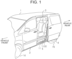
- FIG. 1 is a schematic diagram showing the plug-in hybrid electric vehicle 1 of the present embodiment.
- the plug-in hybrid electric vehicle 1 includes a front door 2, a vehicle opening 3, and a slide door 4 on a vehicle side face.
- the vehicle opening 3 is opened and closed with the slide door 4 that moves in the vehicle front-rear direction.
- a step panel 5 is disposed at the bottom of the vehicle opening 3.
- the step panel 5 is disposed at the bottom of a floor panel 100 that constitutes a floor of the plug-in hybrid electric vehicle 1.
- a guide rail 11 extending in the vehicle front-rear direction of the plug-in hybrid electric vehicle 1 is fixed to a lower face of the step panel 5.
- a front end of the guide rail 11 is located rearward of front wheels 14.
- a rear end of the guide rail 11 is located forward of rear wheels 15.
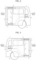
- FIG. 2 is a plan view of the slide door 4 included in the plug-in hybrid electric vehicle 1 in a vehicle side view viewed from the left side.
- the plug-in hybrid electric vehicle 1 includes an oil filler port 17 disposed on a vehicle left side face and rearward of the slide door 4.
- the plug-in hybrid electric vehicle 1 includes an upper rail 7, a center rail 9, and the guide rail 11 that are disposed around the vehicle opening 3.
- the upper rail 7 is disposed above the vehicle opening 3.
- the guide rail 11 is disposed below the vehicle opening 3.
- the center rail 9 is disposed on the vehicle side face rearward of the vehicle opening 3. The position of the center rail 9 in the vehicle-height direction is below the upper rail 7 and above the guide rail 11.
- the slide door 4 includes a slide door body 6, an upper hinge unit 8, a center hinge unit 10, and a guide hinge unit 12.
- the upper hinge unit 8 and the guide hinge unit 12 are fixed near a front end of the slide door body 6 in the vehicle-length direction.
- the center hinge unit 10 is fixed near a rear end of the slide door body 6 in the vehicle-length direction.
- the upper hinge unit 8 is fixed to an upper end portion of the slide door body 6.
- the guide hinge unit 12 is fixed to a lower end portion of the slide door body 6.
- the center hinge unit 10 is fixed to a central portion of the slide door body 6 in the height direction.
- the upper hinge unit 8 is movably supported on the upper rail 7.
- the center hinge unit 10 is movably supported on the center rail 9.
- the guide hinge unit 12 is movably supported on the guide rail 11. Accordingly, the upper hinge unit 8, the center hinge unit 10, and the guide hinge unit 12 couple the slide door body 6 and the vehicle side face.
- the slide door body 6 can move relative to the vehicle side face by the upper hinge unit 8, the center hinge unit 10, and the guide hinge unit 12 moving along the upper rail 7, the center rail 9, and the guide rail 11. That is, the upper rail 7, the center rail 9, and the guide rail 11 define the moving direction of the slide door 4.
- FIG. 3 is a plan view of a slide door 4 included in the plug-in hybrid electric vehicle 1 in a vehicle side view viewed from the right side.
- the plug-in hybrid electric vehicle 1 includes a charging lid 61 disposed on a vehicle right side face and rearward of the slide door 4. Inside the charging lid 61, a first charging port 18 and a second charging port 19, which will be described further below, are disposed.
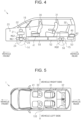
- FIG. 4 schematically shows the internal structure of the plug-in hybrid electric vehicle 1 in a vehicle side view viewed from the left side.
- the plug-in hybrid electric vehicle 1 is a minivan type vehicle having a vehicle cabin 16 and a luggage space that are not separated from each other.
- the plug-in hybrid electric vehicle 1 includes an engine compartment 20 located forward of the vehicle cabin 16. Inside the engine compartment 20, as a power source, an engine 21, a first motor generator MG1, a second motor generator MG2, a power control unit 22, a power split device 23, and a reduction mechanism 24 are disposed.
- the floor panel 100 constitutes the floor of the plug-in hybrid electric vehicle 1.
- a first row seat 30, a second row seat 31, and a third row seat 32 are disposed on the floor panel 100.
- the second row seat 31 is located rearward of the first row seat 30.
- the first row seat 30 is located rearward of the front wheels 14.
- the second row seat 31 is located forward of the rear wheels 15.
- the plug-in hybrid electric vehicle 1 includes a branch box 41 disposed below the first row seat 30 and above the floor panel 100.
- the branch box 41 is a high-voltage system component. Details of the branch box 41 will be described further below.
- the plug-in hybrid electric vehicle 1 includes an on-board charger 40 and a DC-DC converter 42 that are disposed rearward of an axle of the rear wheels 15 and above the floor panel 100. Details of the on-board charger 40 and the DC-DC converter 42 will be described further below.
- the on-board charger 40 and the DC-DC converter 42 are high-voltage system components.
- a battery 50 Under the floor panel 100 of the plug-in hybrid electric vehicle 1, a battery 50, a fuel tank 52, a muffler 53, a rear wheel driving motor generator MGR, and a rear wheel reduction mechanism 56 are disposed.
- the battery 50 stores electric power to be supplied to the first motor generator MG1, the second motor generator MG2, and the rear wheel driving motor generator MGR.
- the fuel tank 52 stores fuel to be supplied to the engine 21.
- the muffler 53 reduces an exhaust sound.
- the fuel tank 52 is disposed rearward of the battery 50.
- the rear wheel driving motor generator MGR is disposed rearward of the fuel tank 52.
- the muffler 53 is disposed rearward of the rear wheel driving motor generator MGR.
- FIG. 5 schematically shows the arrangement of the seats in a vehicle top view, looking down the plug-in hybrid electric vehicle 1 from above.
- the first row seat 30 includes a driver's seat and a passenger seat.
- the second row seat 31 includes two independent seats.
- the third row seat 32 is located rearward of the second row seat 31.
- First slide rails 45 extending in the vehicle front-rear direction are disposed rearward of the branch box 41.
- Second slide rails 46 extending in the vehicle front-rear direction are disposed rearward of the first slide rails 45. All four of the first slide rails 45 are disposed on the floor panel 100. Two of the second slide rails 46 located on the vehicle center are disposed on the floor panel 100. The remaining two side rails 46 are disposed on the vehicle side faces inside the vehicle cabin 16.
- the branch box 41 is disposed under the driver's seat. Accordingly, the height of the floor panel 100 in a portion located between the driver's seat and the passenger seat is equal to the height in a portion where the first slide rails 45 and the second slide rails 46 are disposed.
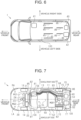
- FIG. 7 is a schematic diagram in a vehicle top view, looking down the plug-in hybrid electric vehicle 1 from above as with FIG. 5 .
- FIG. 7 schematically shows the arrangement of devices disposed under the floor panel 100.
- FIG. 7 also schematically shows the arrangement of the on-board charger 40, the branch box 41, and the DC-DC converter 42 disposed on or above the floor panel 100.
- the plug-in hybrid electric vehicle 1 is divided into an area RA on the vehicle right side and an area LA on the vehicle left side at a center line CL indicating the center of the plug-in hybrid electric vehicle 1 in the vehicle-width direction as a boundary.
- the plug-in hybrid electric vehicle 1 includes the guide rail 11 for sliding the slide door 4 under the floor panel 100.
- the guide rail 11 is disposed overlapping a part of the battery 50 in the vehicle front-rear direction.
- the guide rail 11 has a curved portion 13 that is curved inward in the vehicle-width direction toward the front of the vehicle. When the slide door 4 is closed, the slide door 4 is pulled inward in the vehicle-width direction along the curved portion 13 of the guide rail 11.
- the plug-in hybrid electric vehicle 1 includes an exhaust pipe 54 that is disposed under the floor panel 100 and guides exhaust from the engine 21 to the rear of the vehicle.
- the exhaust pipe 54 connects the engine 21 and the muffler 53.
- the exhaust pipe 54 is disposed closer to the vehicle right side and disposed in the area RA on the vehicle right side. That is, the exhaust pipe 54 is disposed closer to the side opposite to the side to which the battery 50 is closer in the vehicle-width direction.
- the exhaust pipe 54 is disposed through between the battery 50 and the guide rail 11.
- the exhaust pipe 54 is bent outward in the vehicle-width direction along the curved portion 13 of the guide rail 11.
- the fuel tank 52 is disposed rearward of the battery 50.
- the fuel tank 52 is connected to the oil filler port 17 through an oil filler pipe 62.
- the branch box 41 is connected to the battery 50 through a second wire harness 82.
- the second wire harness 82 is routed between the battery 50 and the exhaust pipe 54.
- the DC-DC converter 42 is connected to the branch box 41 through a third wire harness 83.
- the third wire harness 83 is routed between the battery 50 and the exhaust pipe 54.
- the third wire harness 83 is routed in the vehicle front-rear direction through the side of the fuel tank 52.
- the branch box 41 is connected to the second charging port 19 through a fourth wire harness 84.
- the fourth wire harness 84 is routed between the battery 50 and the exhaust pipe 54.
- the fourth wire harness 84 is routed in the vehicle front-rear direction through the side of the fuel tank 52.
- the rear wheel driving motor generator MGR is connected to the power control unit 22 through a fifth wire harness 85.
- the fifth wire harness 85 is routed between the battery 50 and the exhaust pipe 54.
- the fifth wire harness 85 is routed in the vehicle front-rear direction through the side of the fuel tank 52.
- the on-board charger 40 is connected to the first charging port 18 through a sixth wire harness 86.
- the battery 50 is connected to the power control unit 22 through a seventh wire harness 87.
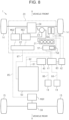
- FIG. 8 schematically shows the configuration of a driving system and the configuration of an electrical system in the plug-in hybrid electric vehicle 1 of the embodiment.
- the second motor generator MG2 is connected to the battery 50 through the power control unit 22.
- the second motor generator MG2 is coupled to the front wheels 14 through the reduction mechanism 24.
- the rotational power of the second motor generator MG2 is transmitted to the front wheels 14 through the reduction mechanism 24 that is an example of a power transmission mechanism. That is, the second motor generator MG2 functions as a driving motor.
- the engine 21 is coupled to the front wheels 14 through the power split device 23 and the reduction mechanism 24.
- the power split device 23 is an example of a power transmission mechanism as with the reduction mechanism 24. That is, the rotational power of the engine 21 is transmitted to the front wheels 14 through the power transmission mechanism.
- the first motor generator MG1 is also coupled to the power split device 23.
- the first motor generator MG1 is, for example, a three-phase AC motor generator.
- the power split device 23 is a planetary gear mechanism. The power split device 23 can split the driving force between the engine 21, the first motor generator MG1, and the front wheels 14.
- the first motor generator MG1 receives the driving force of the engine 21 and the driving force from the front wheels 14 to generate electric power.
- the first motor generator MG1 also serves as a starter that drives a crankshaft that is an output shaft of the engine 21 when the engine 21 is started.
- the first motor generator MG1 functions as an electric motor that generates a driving force in response to the supply of electric power from the battery 50. That is, the first motor generator MG1 functions as a driving motor.
- the first motor generator MG1 and the second motor generator MG2 are connected to the battery 50 through the power control unit 22 and the seventh wire harness 87.
- AC electric power generated by the first motor generator MG1 is converted to DC electric power by the power control unit 22.
- the battery 50 is charged with the DC electric power converted by the power control unit 22 through the seventh wire harness 87. That is, the power control unit 22 functions as an inverter.
- DC electric power of the battery 50 is supplied to the power control unit 22 through the seventh wire harness 87.
- the supplied DC electric power is converted to AC electric power by the power control unit 22.
- the AC electric power converted by the power control unit 22 is supplied to the second motor generator MG2.
- the second motor generator MG2 When the plug-in hybrid electric vehicle 1 is decelerated, the second motor generator MG2 generates electric power using the driving force from the front wheels 14. Then, the battery 50 is charged with the generated electric power. That is, the plug-in hybrid electric vehicle 1 performs regenerative charging. At this time, the second motor generator MG2 functions as an electric generator. AC electric power generated by the second motor generator MG2 is converted to DC electric power by the power control unit 22. The battery 50 is charged with the DC electric power converted by the power control unit 22 through the seventh wire harness 87.
- the rear wheel driving motor generator MGR is also connected to the battery 50 through the power control unit 22.
- the rear wheel driving motor generator MGR is coupled to the rear wheels 15 through the rear wheel reduction mechanism 56.
- DC electric power of the battery 50 is converted to AC electric power by the power control unit 22 and then supplied to the rear wheel driving motor generator MGR through the fifth wire harness 85.
- the rear wheel driving motor generator MGR is an electric motor that drives the rear wheels 15 using the electric power supplied from the battery 50. That is, the rear wheel driving motor generator MGR functions as a driving motor.
- the rear wheel driving motor generator MGR When the plug-in hybrid electric vehicle 1 is decelerated, the rear wheel driving motor generator MGR generates electric power using the driving force from the rear wheels 15. Then, the battery 50 is charged with the generated electric power. At this time, the rear wheel driving motor generator MGR functions as an electric generator. AC electric power generated by the rear wheel driving motor generator MGR is converted to DC electric power by the power control unit 22. Then, the battery 50 is charged with the DC electric power converted by the power control unit 22 through the fifth wire harness 85.
- the plug-in hybrid electric vehicle 1 includes the on-board charger 40, the branch box 41, and the DC-DC converter 42.
- the plug-in hybrid electric vehicle 1 also includes the first charging port 18 and the second charging port 19 as charging ports into which a charging plug is inserted from outside of the vehicle.
- the first charging port 18 is a charging port used for normal charging using an AC power source of, for example, 100 V or 200 V.
- the second charging port 19 is a charging port used for fast charging using a DC high-voltage power source of, for example, 50 kW.
- the on-board charger 40 is connected to the battery 50 through the first wire harness 81.
- the branch box 41 is connected to the battery 50 through the second wire harness 82.
- the DC-DC converter 42 is connected to the branch box 41 through the third wire harness 83.
- the on-board charger 40 is connected to the first charging port 18 through the sixth wire harness 86.
- the on-board charger 40 converts AC electric power input into the on-board charger 40 from the AC power source connected to the first charging port 18 into DC electric power and outputs the DC electric power to charge the battery 50. That is, the plug-in hybrid electric vehicle 1 can use an AC power source as an external power source for charging the battery 50.
- the branch box 41 is connected to the second charging port 19 through the fourth wire harness 84.
- a DC power source is connected to the second charging port 19.
- DC electric power input from the DC power source connected to the second charging port 19 is supplied to the battery 50 through the branch box 41. That is, the plug-in hybrid electric vehicle 1 can use a DC power source as an external power source for charging the battery 50.
- the wire harness When the wire harness is routed above the fuel tank 52, it is necessary to install the floor panel 100 at a position higher than the wire harness in order to make the floor of the plug-in hybrid electric vehicle 1 flat.
- the position of the floor panel 100 can be made lower than that when the wire harness is routed above the fuel tank 52. Lowering the position of the floor panel 100 widens the vehicle cabin space in the height direction.
- the present embodiment can be modified as described below to be implemented.
- the present embodiment and the following modifications can be implemented in combination with each other without any technical inconsistency.
- the plug-in hybrid electric vehicle 1 may control the driving motor inside the engine compartment 20 and the rear wheel driving motor generator MGR using different power control units.
- the plug-in hybrid electric vehicle 1 may further include a power control unit outside the engine compartment 20, in addition to the power control unit 22 inside the engine compartment 20.
- the fuel tank 52 may be disposed forward of the battery 50, as long as the wire harness is routed in the vehicle front-rear direction through the side of the fuel tank 52.
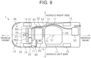
- FIG. 9 is a schematic diagram showing the arrangement of devices disposed under the floor panel 100 in the plug-in hybrid electric vehicle 1. As shown in FIG. 9 , the seventh wire harness 87 that connects the power control unit 22 and the battery 50 is routed in the vehicle front-rear direction through the side of the fuel tank 52. Furthermore, the fuel tank 52 is disposed forward of the battery 50.
- no wire harness may be routed between the battery 50 and the exhaust pipe 54, as long as a wire harness is routed in the vehicle front-rear direction through the side of the fuel tank 52.
- the seventh wire harness 87 that connects the power control unit 22 and the battery 50 is routed in the vehicle front-rear direction through the side of the fuel tank 52.
- no wire harness is routed between the battery 50 and the exhaust pipe 54.
- the first wire harness 81 may not be routed between the battery 50 and the exhaust pipe 54, as long as a wire harness is routed in the vehicle front-rear direction through the side of the fuel tank 52.
- the seventh wire harness 87 that connects the power control unit 22 and the battery 50 is routed in the vehicle front-rear direction through the side of the fuel tank 52.
- the first wire harness 81 that connects the battery 50 and the on-board charger 40 may not be routed between the battery 50 and the exhaust pipe 54.
- the third wire harness 83 may not be routed between the battery 50 and the exhaust pipe 54, as long as a wire harness is routed in the vehicle front-rear direction through the side of the fuel tank 52.
- the seventh wire harness 87 that connects the power control unit 22 and the battery 50 is routed in the vehicle front-rear direction through the side of the fuel tank 52.
- the third wire harness 83 that connects the branch box 41 and the DC-DC converter 42 may not be routed between the battery 50 and the exhaust pipe 54.
- the fourth wire harness 84 may not be routed between the battery 50 and the exhaust pipe 54, as long as a wire harness is routed in the vehicle front-rear direction through the side of the fuel tank 52.
- the seventh wire harness 87 that connects the power control unit 22 and the battery 50 is routed in the vehicle front-rear direction through the side of the fuel tank 52.
- the fourth wire harness 84 that connects the second charging port 19 and the branch box 41 may not be routed between the battery 50 and the exhaust pipe 54.
- the plug-in hybrid electric vehicle 1 may not include the slide door 4, the upper rail 7, the center rail 9, and the guide rail 11.
- the plug-in hybrid electric vehicle 1 may include the slide door 4, the upper rail 7, the center rail 9, and the guide rail 11 only on one side of the vehicle.
- the first charging port 18 may be disposed in a place other than the place on the vehicle side face and rearward of the slide door 4.
- the second charging port 19 may be disposed in a place other than the place on the vehicle side face and rearward of the slide door 4.
- the plug-in hybrid electric vehicle 1 may not include the first charging port 18. That is, the plug-in hybrid electric vehicle 1 may include only the second charging port 19 as the charging port into which the charging plug is inserted.
- the plug-in hybrid electric vehicle 1 may not include the second charging port 19. That is, the plug-in hybrid electric vehicle 1 may include only the first charging port 18 as the charging port into which the charging plug is inserted.
- the plug-in hybrid electric vehicle 1 may not include the branch box 41.
- the plug-in hybrid electric vehicle 1 may not include the branch box 41.
- the branch box 41 may be disposed at a position other than the position under the right side seat in the first row seat 30.
- the branch box 41 may be disposed under the left side seat in the first row seat 30.
- the branch box 41 may be disposed between the right side seat and the left side seat in the first row seat 30.
- the plug-in hybrid electric vehicle 1 may be an autonomous driving vehicle. In this case, the plug-in hybrid electric vehicle 1 may not include the driver's seat. In this case, the plug-in hybrid electric vehicle 1 includes a right side seat and a left side seat as the first row seat 30.
- the branch box 41 is disposed under the right side seat. In the plug-in hybrid electric vehicle 1, the branch box 41 may be disposed at a position other than the position under the right side seat. For example, the branch box 41 may be disposed under the left side seat. For example, the branch box 41 may be disposed between the right side seat and the left side seat.
- the battery 50 may not be disposed across both the area RA on the vehicle right side and the area LA on the vehicle left side through the center in the vehicle-width direction, as long as the wire harness is routed in the vehicle front-rear direction through the side of the fuel tank 52.
- the battery 50 may not be disposed closer to one side in the vehicle-width direction such that the gravity center position 51 of the battery 50 is offset from the center in the vehicle-width direction, as long as the wire harness is routed in the vehicle front-rear direction through the side of the fuel tank 52.
- the wire harness may not be routed closer to the side opposite to the side to which the battery 50 is closer in the vehicle-width direction, as long as the wire harness is routed in the vehicle front-rear direction through the side of the fuel tank 52.
Landscapes
- Engineering & Computer Science (AREA)
- Mechanical Engineering (AREA)
- Transportation (AREA)
- Combustion & Propulsion (AREA)
- Chemical & Material Sciences (AREA)
- Power Engineering (AREA)
- Aviation & Aerospace Engineering (AREA)
- Life Sciences & Earth Sciences (AREA)
- Sustainable Development (AREA)
- Sustainable Energy (AREA)
- General Engineering & Computer Science (AREA)
- Hybrid Electric Vehicles (AREA)
- Cooling, Air Intake And Gas Exhaust, And Fuel Tank Arrangements In Propulsion Units (AREA)
- Electric Propulsion And Braking For Vehicles (AREA)
- Arrangement Or Mounting Of Propulsion Units For Vehicles (AREA)
Applications Claiming Priority (1)
| Application Number | Priority Date | Filing Date | Title |
|---|---|---|---|
| JP2024000342A JP2025106752A (ja) | 2024-01-04 | 2024-01-04 | プラグインハイブリッド車両 |
Publications (2)
| Publication Number | Publication Date |
|---|---|
| EP4582279A2 true EP4582279A2 (de) | 2025-07-09 |
| EP4582279A3 EP4582279A3 (de) | 2025-07-30 |
Family
ID=93843566
Family Applications (1)
| Application Number | Title | Priority Date | Filing Date |
|---|---|---|---|
| EP24218278.0A Pending EP4582279A3 (de) | 2024-01-04 | 2024-12-09 | Steckbares hybridelektrofahrzeug |
Country Status (5)
| Country | Link |
|---|---|
| US (1) | US20250222757A1 (de) |
| EP (1) | EP4582279A3 (de) |
| JP (1) | JP2025106752A (de) |
| KR (1) | KR20250107101A (de) |
| CN (1) | CN120245707A (de) |
Citations (1)
| Publication number | Priority date | Publication date | Assignee | Title |
|---|---|---|---|---|
| JP2021160519A (ja) | 2020-03-31 | 2021-10-11 | マツダ株式会社 | 車両の下部構造 |
Family Cites Families (4)
| Publication number | Priority date | Publication date | Assignee | Title |
|---|---|---|---|---|
| JP5641141B2 (ja) * | 2011-07-19 | 2014-12-17 | トヨタ自動車株式会社 | 車両 |
| JP6286459B2 (ja) * | 2016-02-12 | 2018-02-28 | 本田技研工業株式会社 | 車両 |
| JP6477594B2 (ja) * | 2016-05-19 | 2019-03-06 | トヨタ自動車株式会社 | ピラーレス車両の燃料タンク配置構造 |
| JP6922763B2 (ja) * | 2018-01-30 | 2021-08-18 | トヨタ自動車株式会社 | 車両下部構造 |
-
2024
- 2024-01-04 JP JP2024000342A patent/JP2025106752A/ja active Pending
- 2024-12-04 KR KR1020240178295A patent/KR20250107101A/ko active Pending
- 2024-12-04 US US18/967,802 patent/US20250222757A1/en active Pending
- 2024-12-09 EP EP24218278.0A patent/EP4582279A3/de active Pending
- 2024-12-18 CN CN202411867351.2A patent/CN120245707A/zh active Pending
Patent Citations (1)
| Publication number | Priority date | Publication date | Assignee | Title |
|---|---|---|---|---|
| JP2021160519A (ja) | 2020-03-31 | 2021-10-11 | マツダ株式会社 | 車両の下部構造 |
Also Published As
| Publication number | Publication date |
|---|---|
| US20250222757A1 (en) | 2025-07-10 |
| JP2025106752A (ja) | 2025-07-16 |
| CN120245707A (zh) | 2025-07-04 |
| KR20250107101A (ko) | 2025-07-11 |
| EP4582279A3 (de) | 2025-07-30 |
Similar Documents
| Publication | Publication Date | Title |
|---|---|---|
| JP4293250B2 (ja) | ハイブリッド車両 | |
| CN108367660B (zh) | 高电压控制设备单元的搭载构造 | |
| US9861018B2 (en) | Wiring protective cover structure for electric drive vehicle | |
| KR20110112479A (ko) | 차량 | |
| CN103648834A (zh) | 车辆 | |
| US20250222757A1 (en) | Plug-in hybrid electric vehicle | |
| EP4582275A1 (de) | Stecker in einem hybridelektrofahrzeug | |
| EP4400346A1 (de) | Elektrifiziertes fahrzeug | |
| EP4582277A1 (de) | Steckbares hybridelektrofahrzeug | |
| US12515512B2 (en) | Electrified vehicle | |
| EP4588700A1 (de) | Steckbares hybridelektrofahrzeug | |
| EP4582276A1 (de) | Steckbares hybridelektrofahrzeug | |
| US20260084554A1 (en) | Electric vehicle | |
| EP4707010A1 (de) | Steckbares hybridelektrofahrzeug | |
| US20260061825A1 (en) | Plug-in hybrid electric vehicle | |
| KR20260032880A (ko) | 플러그인 하이브리드 차량 | |
| EP4707008A1 (de) | Steckbares hybridelektrofahrzeug | |
| JP2026043737A (ja) | ピックアップトラック | |
| JP2024095204A (ja) | 車両 | |
| JP2026014017A (ja) | 電動車両 |
Legal Events
| Date | Code | Title | Description |
|---|---|---|---|
| PUAI | Public reference made under article 153(3) epc to a published international application that has entered the european phase |
Free format text: ORIGINAL CODE: 0009012 |
|
| STAA | Information on the status of an ep patent application or granted ep patent |
Free format text: STATUS: REQUEST FOR EXAMINATION WAS MADE |
|
| PUAL | Search report despatched |
Free format text: ORIGINAL CODE: 0009013 |
|
| 17P | Request for examination filed |
Effective date: 20241209 |
|
| AK | Designated contracting states |
Kind code of ref document: A2 Designated state(s): AL AT BE BG CH CY CZ DE DK EE ES FI FR GB GR HR HU IE IS IT LI LT LU LV MC ME MK MT NL NO PL PT RO RS SE SI SK SM TR |
|
| AK | Designated contracting states |
Kind code of ref document: A3 Designated state(s): AL AT BE BG CH CY CZ DE DK EE ES FI FR GB GR HR HU IE IS IT LI LT LU LV MC ME MK MT NL NO PL PT RO RS SE SI SK SM TR |
|
| RIC1 | Information provided on ipc code assigned before grant |
Ipc: B60K 1/04 20190101AFI20250624BHEP Ipc: B60K 15/04 20060101ALI20250624BHEP Ipc: B60K 15/063 20060101ALI20250624BHEP Ipc: B60L 53/18 20190101ALI20250624BHEP Ipc: B60L 53/14 20190101ALI20250624BHEP |
|
| GRAP | Despatch of communication of intention to grant a patent |
Free format text: ORIGINAL CODE: EPIDOSNIGR1 |
|
| STAA | Information on the status of an ep patent application or granted ep patent |
Free format text: STATUS: GRANT OF PATENT IS INTENDED |
|
| INTG | Intention to grant announced |
Effective date: 20260311 |