EP4582131A2 - Neupositionierungshülle mit variabler grösse - Google Patents
Neupositionierungshülle mit variabler grösse Download PDFInfo
- Publication number
- EP4582131A2 EP4582131A2 EP25177819.7A EP25177819A EP4582131A2 EP 4582131 A2 EP4582131 A2 EP 4582131A2 EP 25177819 A EP25177819 A EP 25177819A EP 4582131 A2 EP4582131 A2 EP 4582131A2
- Authority
- EP
- European Patent Office
- Prior art keywords
- sheath
- repositioning
- repositioning sheath
- variable size
- component
- Prior art date
- Legal status (The legal status is an assumption and is not a legal conclusion. Google has not performed a legal analysis and makes no representation as to the accuracy of the status listed.)
- Pending
Links
Images


Classifications
-
- A—HUMAN NECESSITIES
- A61—MEDICAL OR VETERINARY SCIENCE; HYGIENE
- A61B—DIAGNOSIS; SURGERY; IDENTIFICATION
- A61B17/00—Surgical instruments, devices or methods
- A61B17/00234—Surgical instruments, devices or methods for minimally invasive surgery
-
- A—HUMAN NECESSITIES
- A61—MEDICAL OR VETERINARY SCIENCE; HYGIENE
- A61B—DIAGNOSIS; SURGERY; IDENTIFICATION
- A61B17/00—Surgical instruments, devices or methods
- A61B17/34—Trocars; Puncturing needles
- A61B17/3417—Details of tips or shafts, e.g. grooves, expandable, bendable; Multiple coaxial sliding cannulas, e.g. for dilating
- A61B17/3421—Cannulas
- A61B17/3439—Cannulas with means for changing the inner diameter of the cannula, e.g. expandable
-
- A—HUMAN NECESSITIES
- A61—MEDICAL OR VETERINARY SCIENCE; HYGIENE
- A61B—DIAGNOSIS; SURGERY; IDENTIFICATION
- A61B17/00—Surgical instruments, devices or methods
- A61B17/34—Trocars; Puncturing needles
- A61B17/3468—Trocars; Puncturing needles for implanting or removing devices, e.g. prostheses, implants, seeds, wires
-
- A—HUMAN NECESSITIES
- A61—MEDICAL OR VETERINARY SCIENCE; HYGIENE
- A61M—DEVICES FOR INTRODUCING MEDIA INTO, OR ONTO, THE BODY; DEVICES FOR TRANSDUCING BODY MEDIA OR FOR TAKING MEDIA FROM THE BODY; DEVICES FOR PRODUCING OR ENDING SLEEP OR STUPOR
- A61M39/00—Tubes, tube connectors, tube couplings, valves, access sites or the like, specially adapted for medical use
- A61M39/02—Access sites
-
- A—HUMAN NECESSITIES
- A61—MEDICAL OR VETERINARY SCIENCE; HYGIENE
- A61M—DEVICES FOR INTRODUCING MEDIA INTO, OR ONTO, THE BODY; DEVICES FOR TRANSDUCING BODY MEDIA OR FOR TAKING MEDIA FROM THE BODY; DEVICES FOR PRODUCING OR ENDING SLEEP OR STUPOR
- A61M60/00—Blood pumps; Devices for mechanical circulatory actuation; Balloon pumps for circulatory assistance
- A61M60/10—Location thereof with respect to the patient's body
- A61M60/122—Implantable pumps or pumping devices, i.e. the blood being pumped inside the patient's body
- A61M60/126—Implantable pumps or pumping devices, i.e. the blood being pumped inside the patient's body implantable via, into, inside, in line, branching on, or around a blood vessel
- A61M60/13—Implantable pumps or pumping devices, i.e. the blood being pumped inside the patient's body implantable via, into, inside, in line, branching on, or around a blood vessel by means of a catheter allowing explantation, e.g. catheter pumps temporarily introduced via the vascular system
-
- A—HUMAN NECESSITIES
- A61—MEDICAL OR VETERINARY SCIENCE; HYGIENE
- A61M—DEVICES FOR INTRODUCING MEDIA INTO, OR ONTO, THE BODY; DEVICES FOR TRANSDUCING BODY MEDIA OR FOR TAKING MEDIA FROM THE BODY; DEVICES FOR PRODUCING OR ENDING SLEEP OR STUPOR
- A61M60/00—Blood pumps; Devices for mechanical circulatory actuation; Balloon pumps for circulatory assistance
- A61M60/10—Location thereof with respect to the patient's body
- A61M60/122—Implantable pumps or pumping devices, i.e. the blood being pumped inside the patient's body
- A61M60/126—Implantable pumps or pumping devices, i.e. the blood being pumped inside the patient's body implantable via, into, inside, in line, branching on, or around a blood vessel
- A61M60/135—Implantable pumps or pumping devices, i.e. the blood being pumped inside the patient's body implantable via, into, inside, in line, branching on, or around a blood vessel inside a blood vessel, e.g. using grafting
-
- A—HUMAN NECESSITIES
- A61—MEDICAL OR VETERINARY SCIENCE; HYGIENE
- A61M—DEVICES FOR INTRODUCING MEDIA INTO, OR ONTO, THE BODY; DEVICES FOR TRANSDUCING BODY MEDIA OR FOR TAKING MEDIA FROM THE BODY; DEVICES FOR PRODUCING OR ENDING SLEEP OR STUPOR
- A61M60/00—Blood pumps; Devices for mechanical circulatory actuation; Balloon pumps for circulatory assistance
- A61M60/10—Location thereof with respect to the patient's body
- A61M60/122—Implantable pumps or pumping devices, i.e. the blood being pumped inside the patient's body
- A61M60/126—Implantable pumps or pumping devices, i.e. the blood being pumped inside the patient's body implantable via, into, inside, in line, branching on, or around a blood vessel
- A61M60/148—Implantable pumps or pumping devices, i.e. the blood being pumped inside the patient's body implantable via, into, inside, in line, branching on, or around a blood vessel in line with a blood vessel using resection or like techniques, e.g. permanent endovascular heart assist devices
-
- A—HUMAN NECESSITIES
- A61—MEDICAL OR VETERINARY SCIENCE; HYGIENE
- A61M—DEVICES FOR INTRODUCING MEDIA INTO, OR ONTO, THE BODY; DEVICES FOR TRANSDUCING BODY MEDIA OR FOR TAKING MEDIA FROM THE BODY; DEVICES FOR PRODUCING OR ENDING SLEEP OR STUPOR
- A61M60/00—Blood pumps; Devices for mechanical circulatory actuation; Balloon pumps for circulatory assistance
- A61M60/10—Location thereof with respect to the patient's body
- A61M60/122—Implantable pumps or pumping devices, i.e. the blood being pumped inside the patient's body
- A61M60/165—Implantable pumps or pumping devices, i.e. the blood being pumped inside the patient's body implantable in, on, or around the heart
- A61M60/17—Implantable pumps or pumping devices, i.e. the blood being pumped inside the patient's body implantable in, on, or around the heart inside a ventricle, e.g. intraventricular balloon pumps
- A61M60/174—Implantable pumps or pumping devices, i.e. the blood being pumped inside the patient's body implantable in, on, or around the heart inside a ventricle, e.g. intraventricular balloon pumps discharging the blood to the ventricle or arterial system via a cannula internal to the ventricle or arterial system
-
- A—HUMAN NECESSITIES
- A61—MEDICAL OR VETERINARY SCIENCE; HYGIENE
- A61M—DEVICES FOR INTRODUCING MEDIA INTO, OR ONTO, THE BODY; DEVICES FOR TRANSDUCING BODY MEDIA OR FOR TAKING MEDIA FROM THE BODY; DEVICES FOR PRODUCING OR ENDING SLEEP OR STUPOR
- A61M60/00—Blood pumps; Devices for mechanical circulatory actuation; Balloon pumps for circulatory assistance
- A61M60/20—Type thereof
- A61M60/205—Non-positive displacement blood pumps
- A61M60/216—Non-positive displacement blood pumps including a rotating member acting on the blood, e.g. impeller
-
- A—HUMAN NECESSITIES
- A61—MEDICAL OR VETERINARY SCIENCE; HYGIENE
- A61M—DEVICES FOR INTRODUCING MEDIA INTO, OR ONTO, THE BODY; DEVICES FOR TRANSDUCING BODY MEDIA OR FOR TAKING MEDIA FROM THE BODY; DEVICES FOR PRODUCING OR ENDING SLEEP OR STUPOR
- A61M60/00—Blood pumps; Devices for mechanical circulatory actuation; Balloon pumps for circulatory assistance
- A61M60/40—Details relating to driving
- A61M60/403—Details relating to driving for non-positive displacement blood pumps
- A61M60/408—Details relating to driving for non-positive displacement blood pumps the force acting on the blood contacting member being mechanical, e.g. transmitted by a shaft or cable
- A61M60/411—Details relating to driving for non-positive displacement blood pumps the force acting on the blood contacting member being mechanical, e.g. transmitted by a shaft or cable generated by an electromotor
- A61M60/414—Details relating to driving for non-positive displacement blood pumps the force acting on the blood contacting member being mechanical, e.g. transmitted by a shaft or cable generated by an electromotor transmitted by a rotating cable, e.g. for blood pumps mounted on a catheter
-
- A—HUMAN NECESSITIES
- A61—MEDICAL OR VETERINARY SCIENCE; HYGIENE
- A61M—DEVICES FOR INTRODUCING MEDIA INTO, OR ONTO, THE BODY; DEVICES FOR TRANSDUCING BODY MEDIA OR FOR TAKING MEDIA FROM THE BODY; DEVICES FOR PRODUCING OR ENDING SLEEP OR STUPOR
- A61M60/00—Blood pumps; Devices for mechanical circulatory actuation; Balloon pumps for circulatory assistance
- A61M60/40—Details relating to driving
- A61M60/403—Details relating to driving for non-positive displacement blood pumps
- A61M60/408—Details relating to driving for non-positive displacement blood pumps the force acting on the blood contacting member being mechanical, e.g. transmitted by a shaft or cable
- A61M60/411—Details relating to driving for non-positive displacement blood pumps the force acting on the blood contacting member being mechanical, e.g. transmitted by a shaft or cable generated by an electromotor
- A61M60/416—Details relating to driving for non-positive displacement blood pumps the force acting on the blood contacting member being mechanical, e.g. transmitted by a shaft or cable generated by an electromotor transmitted directly by the motor rotor drive shaft
-
- A—HUMAN NECESSITIES
- A61—MEDICAL OR VETERINARY SCIENCE; HYGIENE
- A61M—DEVICES FOR INTRODUCING MEDIA INTO, OR ONTO, THE BODY; DEVICES FOR TRANSDUCING BODY MEDIA OR FOR TAKING MEDIA FROM THE BODY; DEVICES FOR PRODUCING OR ENDING SLEEP OR STUPOR
- A61M60/00—Blood pumps; Devices for mechanical circulatory actuation; Balloon pumps for circulatory assistance
- A61M60/50—Details relating to control
- A61M60/508—Electronic control means, e.g. for feedback regulation
- A61M60/538—Regulation using real-time blood pump operational parameter data, e.g. motor current
- A61M60/554—Regulation using real-time blood pump operational parameter data, e.g. motor current of blood pressure
-
- A—HUMAN NECESSITIES
- A61—MEDICAL OR VETERINARY SCIENCE; HYGIENE
- A61M—DEVICES FOR INTRODUCING MEDIA INTO, OR ONTO, THE BODY; DEVICES FOR TRANSDUCING BODY MEDIA OR FOR TAKING MEDIA FROM THE BODY; DEVICES FOR PRODUCING OR ENDING SLEEP OR STUPOR
- A61M60/00—Blood pumps; Devices for mechanical circulatory actuation; Balloon pumps for circulatory assistance
- A61M60/80—Constructional details other than related to driving
- A61M60/802—Constructional details other than related to driving of non-positive displacement blood pumps
- A61M60/81—Pump housings
- A61M60/816—Sensors arranged on or in the housing, e.g. ultrasonic flow sensors
-
- A—HUMAN NECESSITIES
- A61—MEDICAL OR VETERINARY SCIENCE; HYGIENE
- A61M—DEVICES FOR INTRODUCING MEDIA INTO, OR ONTO, THE BODY; DEVICES FOR TRANSDUCING BODY MEDIA OR FOR TAKING MEDIA FROM THE BODY; DEVICES FOR PRODUCING OR ENDING SLEEP OR STUPOR
- A61M60/00—Blood pumps; Devices for mechanical circulatory actuation; Balloon pumps for circulatory assistance
- A61M60/80—Constructional details other than related to driving
- A61M60/802—Constructional details other than related to driving of non-positive displacement blood pumps
- A61M60/827—Sealings between moving parts
- A61M60/829—Sealings between moving parts having a purge fluid supply
-
- A—HUMAN NECESSITIES
- A61—MEDICAL OR VETERINARY SCIENCE; HYGIENE
- A61M—DEVICES FOR INTRODUCING MEDIA INTO, OR ONTO, THE BODY; DEVICES FOR TRANSDUCING BODY MEDIA OR FOR TAKING MEDIA FROM THE BODY; DEVICES FOR PRODUCING OR ENDING SLEEP OR STUPOR
- A61M60/00—Blood pumps; Devices for mechanical circulatory actuation; Balloon pumps for circulatory assistance
- A61M60/80—Constructional details other than related to driving
- A61M60/855—Constructional details other than related to driving of implantable pumps or pumping devices
- A61M60/857—Implantable blood tubes
-
- A—HUMAN NECESSITIES
- A61—MEDICAL OR VETERINARY SCIENCE; HYGIENE
- A61M—DEVICES FOR INTRODUCING MEDIA INTO, OR ONTO, THE BODY; DEVICES FOR TRANSDUCING BODY MEDIA OR FOR TAKING MEDIA FROM THE BODY; DEVICES FOR PRODUCING OR ENDING SLEEP OR STUPOR
- A61M60/00—Blood pumps; Devices for mechanical circulatory actuation; Balloon pumps for circulatory assistance
- A61M60/80—Constructional details other than related to driving
- A61M60/855—Constructional details other than related to driving of implantable pumps or pumping devices
- A61M60/865—Devices for guiding or inserting pumps or pumping devices into the patient's body
-
- A—HUMAN NECESSITIES
- A61—MEDICAL OR VETERINARY SCIENCE; HYGIENE
- A61B—DIAGNOSIS; SURGERY; IDENTIFICATION
- A61B17/00—Surgical instruments, devices or methods
- A61B17/00234—Surgical instruments, devices or methods for minimally invasive surgery
- A61B2017/00238—Type of minimally invasive operation
- A61B2017/00243—Type of minimally invasive operation cardiac
Definitions
- Intracardiac heart pump assemblies may be introduced into the heart either surgically or percutaneously and used to deliver blood from one location in the heart or circulatory system to another location in the heart or circulatory system.
- an intracardiac pump when deployed in the heart, can pump blood from the left ventricle of the heart into the aorta, or pump blood from the right ventricle to the pulmonary artery.
- Intracardiac pumps can be powered by a motor located outside of the patient's body or a motor located inside the patient's body.
- Some intracardiac blood pump systems can operate in parallel with the native heart to supplement cardiac output and partially or fully unload components of the heart. Examples of such systems include the IMPELLA ® family of devices (Abiomed, Inc., Danvers MA).
- Intracardiac blood pumps such as those just mentioned may be inserted by a catheterization procedure through the femoral artery, femoral vein, or any other suitable path for delivery of the pump to the left or right side of the heart.
- the intracardiac blood pump may be inserted using an introducer sheath, such as a rigid, fixed diameter sheath, e.g., a peel-away introducer sheath such as the Abiomed Impella CP 14Fr peel-away sheath.
- an introducer sheath may be inserted into the femoral artery through an arteriotomy to create an insertion path for a pump assembly. A portion of the pump assembly may then be advanced through an inner lumen of the introducer sheath and into the artery.
- the inner diameter of a rigid introducer sheath must be large enough to accommodate the largest diameter of the pump assembly, such as the pump head, even if other parts of the pump assembly, such as the catheter, have significantly smaller diameter.
- the introducer sheath may be removed, e.g., a peel-away introducer sheath may be peeled away.
- a repositioning sheath with a smaller diameter than the introducer sheath may then be advanced over the pump assembly and into the arteriotomy.
- Replacing the introducer sheath in this way may help to close any annular gap that would otherwise exist between the arteriotomy and the medical device, and reduce limb ischemia and bleeding at the arteriotomy because of the smaller diameter of the repositioning sheath.
- the repositioning sheath may be more easily attached, e.g. via sutures, to the patient, and thus cause less discomfort than a larger introducer sheath.
- an intracardiac blood pump may be inserted using an expandable introducer sheath.
- an expandable introducer sheath may also be inserted into the femoral artery through an arteriotomy to create an insertion path for a pump assembly.
- the pump assembly may then be inserted through the expandable introducer sheath, stretching the expandable introducer sheath radially to a diameter large enough to accommodate the largest diameter of the pump assembly.
- the expandable introducer sheath may be configured to contract or relax radially to a smaller resting diameter, thereby reducing (compared to a rigid sheath, e.g.
- expandable introducer sheath assemblies may not include a mechanism to tighten down the expandable sheath on a catheter at a hub of the expandable introducer sheath.
- an expandable introducer sheath relaxes to a resting state, it may leave an annular gap allowing blood to leak between the inner surface of the expandable introducer sheath and the outer surface of the catheter running through the expandable introducer sheath and potentially thrombose in the annular gap.
- a repositioning sheath may also be inserted into the expandable introducer sheath to fill any such annular gaps. Using the repositioning sheath in this way may thus help reduce bleeding and control the flow of blood within the expandable sheath and repositioning sheath.
- the repositioning sheath may also be configured to be locked in place in a longitudinal direction, thus providing additional stability for long-term support, e.g. in the ICU.
- the present technology relates to systems, devices, and methods for insertion of a device (e.g., intravascular medical device) into a blood vessel using a variable size repositioning sheath.
- a device e.g., intravascular medical device
- a variable size repositioning sheath may be sized in a radial direction to fill at least part of the annular gap between the arteriotomy and the catheter, to minimize unwanted bleeding through the annular gap.
- the introducer sheath may be configured to remain in an insertion path (e.g., an arteriotomy) for relatively long durations (e.g., > 1 hr, >2 hr, >6 hr, or any suitable duration). If an annular gap is allowed to remain between the expandable introducer sheath and the catheter, it can lead to excessive blood ingress into the annular gap, and allow blood to thrombose in the annular gap.
- an outer diameter of the variable size repositioning sheath may decrease by 0.1Fr.
- an outer diameter of the variable size repositioning sheath may increase by 1Fr.
- an outer diameter of the variable size repositioning sheath may increase by 0.5 Fr.
- an outer diameter of the variable size repositioning sheath may increase by 0.2 Fr.
- an outer diameter of the variable size repositioning sheath may increase by 0.1 Fr.
- an outer diameter of the variable size repositioning sheath may decrease by 0.1Fr. Therefore the relationship between the extent of the motion and the incremental increase or decrease in repositioning sheath diameter is largely a matter of design choice. The relationships described above are by way of example.
- Feedback indicating the correspondence may be provided to the operator in any form, including haptic feedback, audio feedback, or any other type of notification such that the operator knows the current size of the variable size repositioning sheath corresponding to the motion applied by the operator.
- there may be gradations along the length of the variable size repositioning sheath where the gradations occur at fixed distances from each other. For example, there may be a gradation every 1mm, 0.5 mm, 10 mm, or any other fixed amount of distance.
- Such examples may advantageously allow the operator to know in real-time or near real-time how their actions at a proximal end of the variable size repositioning sheath are affecting or will affect the outer diameter of the variable size repositioning sheath.
- variable size repositioning sheath may be packaged in the expanded state before being inserted into the arteriotomy after the removal of the peel-away introducer sheath, e.g., to avoid issues that may arise from being stored in a compressed state over a long period of time (e.g., greater than one week, greater than one month, greater than one year, etc.), such as creep of the variable size repositioning sheath when in a compressed state.
- a long period of time e.g., greater than one week, greater than one month, greater than one year, etc.
- variable size repositioning sheath may be sized in a radial direction based on an acceptable recoil at the arteriotomy, i.e. a diameter amount by which the blood vessel at the arteriotomy is able to contract.
- an acceptable recoil at the arteriotomy i.e. a diameter amount by which the blood vessel at the arteriotomy is able to contract.
- a blood vessel at the arteriotomy may be able to recoil to a smaller diameter by about 2Fr or less.
- variable repositioning sheath when using a 14Fr peel-away introducer sheath having a 17.9Fr outer diameter, the variable repositioning sheath may be sized to 15.9 Fr to allow for the vessel to recoil by 2Fr such that the recoiled size of the arteriotomy is about the same as the outer diameter of the repositioning sheath.
- the variable size repositioning sheath may also be configured to allow for further recoil which may take place after the insertion of the variable size repositioning sheath.
- variable size repositioning sheath may be sized with a sizing device that may include a ratchet-type or gear-type inner repositioning sheath, a mandrel-type inner repositioning sheath, a star-shaped inner repositioning sheath, a cam-type inner repositioning sheath, or an oval-shaped inner repositioning sheath.
- the variable size repositioning sheath may be sized in response to a motion by an operator.
- the sizing device may convert the motion into a known expansion or contraction of the size of the variable size repositioning sheath.
- the variable size repositioning sheath may be originally packaged in an expanded state having a 16.7Fr outer diameter, and be configured such that a 360 degree counter-clockwise rotation of a handle of the variable size repositioning sheath may translate into a 0.1Fr radial expansion of the outer diameter of the variable size repositioning sheath.
- the operator may thus rotate the handle in a 360 degree counter-clockwise rotation twelve rotations to change the outer diameter size of the variable size repositioning sheath from 16.7Fr to 17.9Fr, so that it may fill a 17.9Fr arteriotomy that is left after a 14Fr peel-away sheath has been removed.
- the expandable introducer sheaths described herein may be inserted into the femoral artery through an arteriotomy to create an insertion path for the pump assembly.
- the expandable introducer sheath may have a resting outer diameter that is smaller than the fixed outer diameter of a peel-away introducer sheath body.
- Use of an introducer sheath capable of expansion may allow a smaller size sheath to be used for insertion and may allow the arteriotomy to spend less time at a larger diameter, notwithstanding the sheath being used for longer durations.
- the arteriotomy may be smaller than if a larger non-expandable sheath is used.
- the blood pump since the blood pump only momentarily passes through vessel, friction between the intracardiac device, expandable introducer sheath, and vessel wall may be minimized and there may be a reduced axial load and reduced stress on the vessel. That is, the expandable introducer sheath body may be a smaller size and therefore not push or pull the vessel along the axis of the insertion/removal path.
- variable size repositioning sheath may be configured to be adjusted in size in a radial direction such that an operator of the sheath assembly can choose, depending on whether the operator is using a peel-away introducer sheath or an expandable introducer sheath, a size of the variable size repositioning sheath that is compatible with the type and size of the introducer sheath used.
- the operator of the sheath assembly may adjust the size of the variable size repositioning sheath in a radial direction to make the variable size repositioning sheath suitable for use after the removal of a peel-away introducer sheath or suitable for use by insertion into an expandable introducer sheath.
- variable size repositioning sheath may include a sizing device for expanding and contracting the radial size of the variable size repositioning sheath.
- the sizing device may be a ratchet-type or gear-type inner repositioning sheath component, a mandrel-type inner repositioning sheath component, a star-shaped inner repositioning sheath component, a cam-type inner repositioning sheath component, or an oval-shaped inner repositioning sheath component.
- the blood pump systems described herein may comprise an intracardiac device including a pump and a cannula, and may be configured to be at least partially inserted within the heart of a patient.
- the blood pump system may be percutaneously inserted into the heart and run in parallel with the native heart to supplement cardiac output, such as the IMPELLA ® family of devices (Abiomed, Inc., Danvers MA).
- the pump may include a pump housing, a rotor, and an opening in the pump housing.
- the rotor may be at least partially positioned within the pump housing such that a motor drives the rotor and the rotor pumps blood through the pump housing while the system is operating.
- the blood pump system may include a cannula with a proximal end that interfaces with the distal end of the pump housing and a distal end with at least one distal opening.
- the pump may be configured to be placed such that cannula extends across an aortic valve of the patient, the distal end being located within a left ventricle of the patient, and the proximal end being located within an aorta of the patient. Blood may thus flow through the cannula's distal opening, through the body of the cannula, and through the pump housing.
- the blood pump may further include a flexible projection extending distally away from the distal end of the cannula, such as a pigtail-shaped flexible projection.
- the blood pump system may further comprise an elongate catheter coupled on its distal end to the motor or to the pump housing.
- the catheter may connect the pump to a controller or other operating device.
- a controller may be configured to operate the blood pump system.
- the controller may be the Automated Impella Controller (AIC) of Abiomed, Inc or any other suitable controller.
- the elongate catheter may house electrical connections, connecting the pump to the controller.
- the blood pump system may further include one or more sensors (e.g., a differential pressure sensor) configured to communicate with the controller or otherwise provide patient health and pump operation data to a clinician or outside device.
- a drive cable may extend through the elongate catheter, and may be configured to drive operation of the rotor, e.g., by controlling the speed at which the rotor spins.
- a variable size repositioning sheath may be configured to be sized in the radial direction using a ratchet-type or gear-type inner repositioning sheath component.
- a ratchet-type or gear-type inner repositioning sheath component may have any type of gear cross-section with teeth.
- the gear may be configured with different sets of teeth that create a fixed change in the size of the variable size repositioning sheath when the inner repositioning sheath component is rotated.
- variable size repositioning sheath component may be configured to be sized in the radial direction using a cam-type inner repositioning sheath.
- the cam-type inner repositioning sheath may be of any cam-type shape, such as round, eccentric, oval, elliptical, hexagonal, star-shaped, etc., such that a rotation of the cam-type inner repositioning sheath component corresponds to an expansion or contraction of the outer diameter of the variable size repositioning sheath.
- variable size repositioning sheath may be configured to be sized in the radial direction using a mandrel-type inner repositioning sheath component. This may be implemented with any of the aspects described above.
- the mandrel-type inner repositioning sheath may be configured with a set number of sizes that the mandrel components can radially expand or contract into.
- the mandrel-type inner repositioning sheath may be configured to expand or contract into five different sizes, where a first of the five sizes corresponds to an outer diameter size for the variable size repositioning sheath that fits into the arteriotomy left from a standard size peel-away introducer sheath (e.g., 17.9 Fr), a second of the five sizes corresponds to an outer diameter size of the variable size repositioning sheath that fits into an expandable introducer sheath (e.g., 14 Fr), and the other three sizes are intermediate sizes between the first and second sizes.
- a standard size peel-away introducer sheath e.g. 17.9 Fr
- a second of the five sizes corresponds to an outer diameter size of the variable size repositioning sheath that fits into an expandable introducer sheath (e.g., 14 Fr)
- the other three sizes are intermediate sizes between the first and second sizes.
- the systems and methods described herein provide a sheath assembly for the insertion of a medical device (e.g., an intracardiac heart pump) into a blood vessel through a vessel aperture.
- the sheath assembly may comprise an introducer sheath and a variable size repositioning sheath.
- the introducer sheath may include a peel-away introducer sheath or an expandable introducer sheath.
- the variable size repositioning sheath may be adjustable in size in a radial direction such that its diameter may be adjusted over a certain range.
- the adjustment range of a variable size repositioning sheath may include a diameter suitable for allowing insertion of the variable size repositioning sheath into an introducer sheath.
- Repositioning sheaths are sometimes packaged with intracardiac devices with a catheter passing through the repositioning sheath, such that the repositioning sheath and the catheter share the same longitudinal central axis.
- the repositioning sheaths of existing systems have a diameter that cannot be significantly changed.
- a fixed-size repositioning sheath may have a diameter that tapers in a longitudinal direction, the diameter cannot be adjusted prior to use. Accordingly, to use a fixed-size repositioning sheath, the repositioning sheath must be moved in a longitudinal direction relative to the catheter, and into the arteriotomy before being locked in place.
- a repositioning sheath with a fixed size or fixed diameter may be not always be effective in occluding the annular gap between the arteriotomy and the catheter to prevent large leaks and reduce the risk of limb ischemia.
- a variable size repositioning sheath's adjustability in size in the radial direction may aid in insertion into a blood vessel, the size of which may vary depending on patient characteristics (e.g. age, medical condition) or procedure characteristics (e.g. length, complexity, instruments used).
- patient characteristics e.g. age, medical condition
- procedure characteristics e.g. length, complexity, instruments used.
- repositioning sheaths are often packaged together with an intracardiac device, and with a catheter running through the repositioning sheath, this can prevent an operator from swapping out the packaged repositioning sheath for a different size repositioning sheath.
- variable size repositioning sheath may be packaged at a given size and adjusted in size by the operator immediately prior to (or simultaneously with) sliding the repositioning sheath in place through the arteriotomy. This adjustment may be done, for example, to enable the repositioning sheath to fill at least part of an annular gap between the arteriotomy and an elongate catheter, which can also vary in size depending on patient characteristics and/or procedure characteristics.
- a variable size repositioning sheath having an adjustable diameter may be configured to be compatible with both a peel-away introducer sheath and an expandable-size repositioning sheath.
- the diameter of the arteriotomy may be about 17.9Fr due to the 17.9Fr effective outer diameter of the 14Fr peel-away introducer sheath.
- an elongate catheter may have an outer diameter of about 9Fr.
- replacing a peel-away introducer sheath by a variable size repositioning sheath may help to fill at least part of the annular gap, minimizing unwanted bleeding through the annular gap.
- a variable size repositioning sheath may be fixed relative to an elongate catheter using a device such as a Tuohy-Borst valve.
- peel-away introducer sheaths may be inserted into the femoral artery through an arteriotomy to create an insertion path for the pump assembly.
- a portion of the pump assembly may then be advanced through an inner lumen of the peel-away introducer sheath and into the artery.
- the introducer sheath may then be peeled away, and a variable-size repositioning sheath may then be advanced over the pump assembly and into the arteriotomy.
- an expandable introducer sheath may be inserted into the femoral artery through an arteriotomy to create an insertion path for a pump assembly.
- a portion of the pump assembly may then be advanced through an inner lumen of the expandable introducer sheath and into the artery, where the expandable sheath body may expand and contract between different states to accommodate the medical device.
- the expandable introducer sheath body may be elongated and have a first smaller diameter state for insertion of the introducer sheath body into the arteriotomy, and may then be shortened or allowed to relax into a second larger diameter state once at a desired location.
- the second larger diameter state may be configured to allow the passage of a portion of a medical device through the inner lumen of the introducer sheath, the portion of the medical device having a transverse cross-sectional area larger than a transverse cross-sectional area of the inner lumen in the first smaller diameter state.
- the introducer sheath may be further expanded from a resting state when the sheath is at its desired location, to a larger diameter state when the medical device is passed through the introducer sheath.
- FIG. 1 shows a placement system 100 comprising a peel-away introducer 120 configured to introduce an intracardiac device 130 into a patient's vasculature and a variable size repositioning sheath 110 sized in the radial direction for insertion into the arteriotomy 148 after the removal of the peel-away introducer 120, according to aspects of the disclosure.
- the placement system 100 includes variable size repositioning sheath 110, peel-away introducer sheath 120 and intracardiac device 130.
- FIG. 1 shows an exemplary positioning of peel-away introducer 120 with intracardiac device 130 having been inserted through peel-away introducer sheath 120 and positioned such that the intracardiac device 130 has entered the patient's vasculature.
- the intracardiac device 130 comprises a pump 137.
- Pump 137 comprises a cannula 136, a pump housing 139 with proximal openings, a rotor (not shown), and distal cage 133 with distal openings.
- the operator (not the patient) is used as the point of reference, such that "proximal” refers to a direction pointing toward the operator or a position closer to the operator, and “distal” refers to a direction pointing away from the operator or a position farther from the operator.
- the pump is configured to be operated by a motor within motor housing 131.
- Elongate catheter 132 is coupled on its distal end to the motor housing 131.
- Elongate catheter 132 defines a central lumen therein.
- elongate catheter 132 may be coupled to pump housing 139.
- the proximal end of cannula 136 interfaces with the distal end of the pump housing 139.
- the distal end of cannula 136 interfaces with distal cage 133, which defines distal openings.
- Cannula 136 defines a lumen therein.
- blood may be pumped through cannula 136 in the proximal direction such that the proximal openings of pump housing 139 serve as blood outflow ports and the distal openings of distal cage 133 serve as blood inflow ports.
- Peel-away introducer sheath 120 comprises a hub 124 and a peel-away introducer sheath body 122.
- the peel-away introducer sheath body 122 is defined by a distal end 128, a proximal end 126, and a lumen extending through the sheath body 122 between the proximal and distal ends.
- the hub 124 is attached to the peel-away introducer sheath body 122.
- fluid e.g., blood
- peel-away introducer sheath 122 is not radially expandable, the inner diameter 125 must be large enough to accommodate the largest diameter of the intracardiac device 130 (e.g., such as the pump head), even if other parts of the pump assembly (e.g., the catheter) have a significantly smaller diameter.
- peel-away introducer 120 may be peeled apart and removed from the patient (e.g., by peeling the peel-away introducer 120 along axial notches or scorings thereon that allow the sheath to be torn axially).
- the peel-away introducer sheath 120 may have a sheath body with a 14Fr inner diameter and a 17.9Fr outer diameter, and may leave an approximately 17.9Fr opening at the arteriotomy 148 in blood vessel 142 and/or at the insertion site 146 of skin 140 after the peel-away introducer sheath 120 is removed.
- Variable size repositioning sheath 110 comprises a hub 114 and variable size repositioning sheath body 112.
- the variable size repositioning sheath body 112 is defined by a distal end 118, a proximal end 116, and a lumen 119 extending through the sheath body 112 between the proximal and distal ends.
- the distal end of the hub 114 is attached to the proximal end 116 of variable size repositioning sheath body 112.
- Hub 114 includes a sizing device 115 that is configured to adjust the outer diameter 117 of variable size repositioning sheath body 112.
- an operator may adjust the outer diameter 117 by moving (e.g., pressing, toggling, twisting, etc.) the proximal end of sizing device 115.
- a translational motion or a rotational motion may cause a radial expansion or a radial contraction of the outer diameter 117 of variable size repositioning sheath body 112.
- FIGS. 3A-3C and 4A-4F Various potential configurations of sizing device 115 are discussed in detail with respect to the examples of FIGS. 3A-3C and 4A-4F .
- FIG. 1 shows the outer diameter 117 of variable size repositioning sheath body 112 being larger than the outer diameter 123 of peel-away introducer sheath body 122, the diagram of FIG. 1 is not meant to show relative dimensions, and outer diameter 117 may be smaller than, equal to, or larger than outer diameter 123.
- variable size repositioning sheath hub 114 may be configured to lock into the introducer sheath hub 124 using a locking mechanism of any suitable type.
- the variable size repositioning sheath hub 114 may lock into the introducer sheath hub 124 using a locking pin, a clamp, a twist lock, a pop lock, a snapping fit, etc.
- the locking mechanism may be further configured to allow the variable size repositioning sheath hub 114 to be rotated with respect to the introducer sheath hub 124 when the two are locked together.
- variable size repositioning sheath 110 may be part of a larger assembly such as a repositioning unit or a guide wire repositioning unit.
- the intracardiac device 130 may be inserted into the femoral artery through an arteriotomy to create an insertion path for the pump assembly.
- a portion of the pump assembly may then be advanced through an inner lumen of the peel-away introducer sheath 120 and into the artery (e.g., blood vessel 142).
- the introducer sheath 120 may be peeled away.
- variable size repositioning sheath 110 may then be advanced, for example, into the arteriotomy to take the place of the removed peel-away introducer sheath 120.
- variable size repositioning sheath 110 may be used to fill the annular gap and prevent bleeding, while still allowing the arteriotomy 148 to undergo an acceptable amount of recoil (e.g., about 0 to about 2Fr).
- variable size repositioning sheath 110 may be configured to be affixed to the patient, e.g. using sutures, to prevent movement of the variable size repositioning sheath 110 relative to the elongate catheter 132 and the potential for patient discomfort.
- the outer diameter 117 of variable size repositioning sheath body 112 may be adjusted such that it is within a range of about 0 to about 2Fr of the outer diameter 123 of peel-away introducer sheath body 122.
- the outer diameter 117 of variable size repositioning sheath body 112 may be set using sizing device 115 to be no smaller than 15.9Fr and no larger than 17.9Fr.
- this adjustment of the outer diameter 117 of variable size repositioning sheath body 112 may be done before the distal end 118 of the variable size repositioning sheath 110 is advanced into the arteriotomy 148 or simultaneous therewith. In some aspects, the outer diameter 117 of variable size repositioning sheath body 112 may be adjusted (or readjusted) after the distal end 118 of variable size repositioning sheath 110 has been inserted into the arteriotomy 148.
- variable size repositioning sheath 110 may be packaged in a state such that the outer diameter 117 is less likely to need to be adjusted before being advanced into the arteriotomy 148 after the removal of the peel-away introducer sheath 120.
- variable size repositioning sheath 110 may be packaged in an expanded state such that its outer diameter 117 is preset using sizing device 115 to a value between 15.9Fr and 17.9Fr (or some other range, if recoil of arteriotomy 148 is expected to be more or less than 0-2Fr).
- the variable size repositioning sheath 110 may be packaged in a state where it needs to be expanded or contracted using sizing device 115 in order to be sized appropriately for insertion into arteriotomy 148.
- variable size repositioning sheath 110 may be adjusted on a patient-by-patient basis, as the inner diameter of blood vessel 142, the distance 144 between skin 140 and blood vessel 142, the size of the arteriotomy 148, and the amount of recoil in the arteriotomy 148, may all vary on a patient-by-patient basis.
- sizing device 115 may be used to adjust the outer diameter 117 of variable size repositioning sheath body 112 to be smaller or larger depending on these patient-specific characteristics.
- the motor of pump 237 may be "onboard," as shown in FIG. 2 , and may be located within the patient's body during operation and may include electrical leads that transmit power to the motor for driving pump 237. In some aspects of the technology, the motor of pump 237 may be located outside of the patient's body and may actuate the rotor via a drive shaft, drive cable, or drive line. For example, the motor of pump 237 may be located within a handle (not shown) of the intracardiac device 130. In some aspects of the technology, a drive cable may extend through elongate catheter body 232 to a rotor located near a proximal end of cannula 236.
- the intracardiac device 230 only momentarily passes through vessel 242, friction between the intracardiac device 230, expandable introducer sheath body 222, and vessel wall may be reduced, and there may also be reduced axial load and reduced stress on vessel 242 (relative to a fixed-diameter introducer sheath). That is, in a relaxed or rest state where no forces are applied to it, the expandable introducer sheath body 222 may have a smaller diameter than a fixed-diameter introducer sheath body (e.g., peel-away introducer sheath body 122) and therefore may not push or pull the vessel 242 and/or the arteriotomy 248. In addition, when the intracardiac device 230 passes through expandable introducer sheath body 222, the vessel 242 and arteriotomy 248 will simply be expanded outward radially.
- a fixed-diameter introducer sheath body e.g., peel-away introducer sheath body 12
- the expandable introducer sheath body 222 may have any suitable structure.
- the expandable introducer sheath body 222 may have a structure comprised of a frame and one or more coatings, or other configurations as described in U.S. Patent Application No. 16/277,378 , published as U.S. Pub. 2019/0247627 , which has been incorporated by reference herein.
- the frame may include a plurality of strands extending longitudinally between a proximal end and a distal end of the frame.
- the frame may also include a smooth coating about the exterior surface and protrusions extending into the lumen along the inner surface.
- the frame may be comprised of at least one of the following materials: Nitinol round wire; Nitinol flat wire; stainless steel round wire; stainless steel flat wire; liquid crystal polymer; polyamide; polyether ether ketone (PEEK); polyethylene; or polytetrafluoroethylene (PTFE).
- the frame may have a braided configuration.
- the frame may be encapsulated by at least one of the following polymers: silicone; thermoplastic polyurethane; styrenic block copolymer (SBC); an elastomer, including a thermoplastic elastomer (TPE); fluorinated ethylene propylene (FEP); or cyclic olefin copolymer (COC).
- a frame and encapsulating material combination such as those just described may permit the sheath body 222 to expand and contract while retaining sufficient rigidity to maintain an open lumen and withstand axial forces when the medical device is inserted or withdrawn, and may further promote a smooth flow of blood along the outer surface of the sheath to reduce the risk of clots (thrombi) forming.
- Variable size repositioning sheath 210 comprises a hub 214 and variable size repositioning sheath body 212.
- the variable size repositioning sheath body 212 is defined by a distal end 218, a proximal end 216, and a lumen 219 extending through the sheath body 212 between the proximal and distal ends.
- the distal end of the hub 214 is attached to the proximal end 216 of variable size repositioning sheath body 212.
- Hub 214 includes a sizing device 215 that is configured to adjust the outer diameter 217 of variable size repositioning sheath body 212.
- an operator may adjust the outer diameter 217 by moving (e.g., pressing, toggling, twisting, etc.) the proximal end of sizing device 215.
- a translational motion or a rotational motion may cause a radial expansion or a radial contraction of the outer diameter 217 of variable size repositioning sheath body 212.
- Various potential configurations of sizing device 215 are discussed in detail with respect to the examples of FIGS. 3A-3C and 4A-4F .
- FIG. 2 shows the outer diameter 217 of variable size repositioning sheath body 212 being larger than the outer diameter 223 of expandable introducer sheath body 222, the diagram of FIG. 2 is not meant to show relative dimensions, and outer diameter 217 may be smaller than, equal to, or larger than outer diameter 223.
- the outer diameter 217 of the variable size repositioning sheath body 212 may be adjusted using sizing device 215 to be smaller than, the same as, or larger than the inner diameter 225 of the expandable introducer sheath body 222 in its relaxed state.
- the expandable introducer sheath body 222 may have an outer diameter 223 of approximately 15.9Fr and an inner diameter 225 of approximately 14.7Fr, and the outer diameter 217 of the variable size repositioning sheath body 212 may be adjusted to be smaller than the 14.7Fr.
- variable size repositioning sheath 210 may further be configured such that it can be clamped or tightened down on the elongate catheter 232 to prevent or limit relative motion between the two in a longitudinal direction.
- the variable size repositioning sheath 210 may be fixed to the elongate catheter 232 with a device such as a Tuohy-Borst valve, which may be arranged within or proximate to hub 214.
- the variable size repositioning sheath 210 may be configured to be attached, e.g. via sutures, to the patient, thus preventing or limiting relative motion between the variable size repositioning sheath 210 and the patient, and, when clamped, between the elongate catheter 232 and the patient.
- variable size repositioning sheath 210 may be packaged such that it is less likely to need to be adjusted if it is used with an expandable introducer sheath 220.
- variable size repositioning sheath 210 may be packaged in a state such that its outer diameter 217 is preset using sizing device 215 to a value less than or equal to 14.7Fr.
- variable size repositioning sheath 210 may be packaged in a state where it needs to be expanded or contracted using sizing device 215 in order to be sized appropriately for insertion into expandable introducer sheath 220.
- the variable size repositioning sheath 210 may be packaged in a state such that the outer diameter 217 is less likely to need to be adjusted if it is used with a standard peel-away introducer sheath, as discussed above in connection with FIG. 1 .
- the operator can simply actuate the sizing device 215 of the variable size repositioning sheath 210 to configure the size of the variable size repositioning sheath body 212 according to their particular needs.
- FIG. 3A depicts an example sizing device configured to expand or contract a size of a variable size repositioning sheath, according to aspects of the technology.
- sizing device 300 comprises variable size repositioning sheath 310 that includes an outer repositioning sheath component 312 with hub 314, inner repositioning sheath component 320, and handle 317.
- the outer repositioning sheath component 312 includes a distal end 318, a proximal end 316, and a tapered cavity or lumen extending therethrough between the proximal and distal ends.
- the inner repositioning sheath component 320 is disposed within the tapered cavity or lumen of outer repositioning sheath component 312.
- Inner repositioning sheath 320 comprises a distal end 328, a proximal end 326, and a lumen 319 extending therethrough between the proximal and distal ends, such that elongate catheter 332 may be inserted through lumen 319.
- a handle 317 is arranged at the proximal end 326 of inner repositioning sheath component 320. In some aspects of the technology, handle 317 may be replaced with a level, tab, gear, or any other device suitable for moving inner repositioning sheath component 320.
- the inner repositioning sheath component 320 may be more rigid than the outer repositioning sheath component 312.
- the inner repositioning sheath component 320 may be reinforced with a sleeve of a different material.
- the inner repositioning sheath component 320 may be a polymer and it may be reinforced with a metal sleeve.
- the inner repositioning sheath component 320 may be made of a material with a greater strength than the outer repositioning sheath component 312.
- the inner repositioning sheath component 320 may comprise a metal frame.
- Allowing inner repositioning sheath component 320 to be more rigid than the outer variable size repositioning sheath component 312 may help to prevent or limit deformation of the inner repositioning sheath component 320 when it acts on the outer repositioning sheath component 312 to expand or contract the outer diameter of the variable size repositioning sheath 310.
- the sizing device may have detents spaced at fixed intervals, so that the operator will get tactile feedback through handle 317 for each increment (e.g., every 0.1Fr, every 0.5Fr, etc.) by which the outer diameter of variable size repositioning sheath has been adjusted.
- the detents may further be configured to provide some resistance or friction against the sizing device being moved, so that the sizing device will tend to hold its setting.
- the sizing device may include circuitry configured to provide audio, visual, and/or haptic feedback (or to provide signals to one or more additional components configured to produce audio, visual, and/or haptic output based thereon). In such cases, the audio, visual, and/or haptic feedback may be delivered in real-time or substantially in real-time.
- the outer surface of the inner repositioning sheath component 320 and the inner surface of the outer repositioning sheath component 312 have complementary tapers.
- moving inner repositioning sheath component 320 in the distal direction relative to the outer repositioning sheath component 312 will cause variable size repositioning sheath 310 to expand the outer diameter of the variable size repositioning sheath 310.
- variable size repositioning sheath 310 may be configured such that moving inner repositioning sheath component 320 in the proximal direction relative to the outer repositioning sheath component 312 will cause or allow the variable size repositioning sheath 310 to contract the outer diameter of the variable size repositioning sheath 310.
- this relative longitudinal motion between the inner repositioning sheath component 320 and the outer repositioning sheath component 312 may be caused by an operator rotating the inner repositioning sheath component 320 (e.g., by the operator rotating the inner repositioning sheath component 320 with handle 317).
- the inner repositioning sheath component 320 and outer repositioning sheath component 312 may be threaded such that rotation of the inner repositioning sheath component 320 is converted into relative longitudinal motion between the inner repositioning sheath component 320 and the outer repositioning sheath component 312.
- this relative motion between the inner repositioning sheath component 320 and the outer repositioning sheath component 312 may be caused by an operator translating the inner repositioning sheath component 320 in the proximal or distal direction (e.g., by the operator sliding the inner repositioning sheath component 320 proximally or distally with handle 317).
- the outer surface of the inner repositioning sheath component 320 and the inner surface of the outer repositioning sheath component 312 may both be tapered in the opposite direction from what is shown in FIG. 3A , such that the outer diameter of the inner repositioning sheath component 320 and the inner diameter of the outer repositioning sheath both reduce toward their proximal ends.
- variable size repositioning sheath 310 may be configured such that each degree of clockwise rotation of the inner repositioning sheath component 320 corresponds to a fixed amount of radial contraction of the outer diameter of the outer repositioning sheath component 312, and each degree of counterclockwise rotation of the inner repositioning sheath component 320 corresponds to a fixed amount of expansion of the outer diameter of the outer repositioning sheath component 312.
- inner cam component 451 may be comprised of a stronger material than outer cam component 450.
- outer cam component 450 may be comprised of a flexible material such as one of the polymers mentioned above.
- inner cam component 451 may be comprised of a rigid material such as a metal.
- Inner cam component 451 has a hole 456 which may form a part of lumen 419.
- FIG. 4C shows six valleys 452 and six peaks 454, any suitable number of peaks and valleys may be used. Similarly, any suitable shape and profile of peaks and valleys may be used such as round, eccentric, oval, elliptical, hexagonal, star-shaped, etc.
- the size of the valleys 452 and peaks 454 (and thus the corresponding size of the thicker sections 456 and thinner sections 458 in outer cam component 450) may be selected to provide a specific amount of expansion and contraction.
- the size of the valleys 452 and peaks 444 may be configured such that variable size repositioning sheath 410 will fit into the arteriotomy left by a standard size peel-away introducer sheath (e.g., a 17.9Fr arteriotomy) when in its expanded state, and will fit into a smaller expandable introducer sheath (e.g., with a 14Fr inner diameter) when in its contracted state.
- a standard size peel-away introducer sheath e.g., a 17.9Fr arteriotomy
- a smaller expandable introducer sheath e.g., with a 14Fr inner diameter
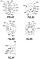
- FIG. 4D shows a cross-sectional area of an example inner repositioning sheath component 420, according to some aspects of the technology.
- inner repositioning sheath component 420 has a mandrel-type mechanism.
- FIG. 4D shows a mandrel-type inner repositioning sheath component 460, which comprises a hole 466 (which may form a part of lumen 419) and mandrel components 460A-460C.
- Mandrel-type inner repositioning sheath component 460 would be mounted on a hub (not shown) configured to actuate mandrel components 460A-460C, such as a hub with a stepped connector like the one described below with respect to FIG. 4F .
- the hub imparts force on mandrel components 460A, 460B, and 460C such that they expand radially outwards, which in turn expands inner repositioning sheath component 420 and variable size repositioning sheath 410 as discussed above.
- the hub when the mandrel-type inner repositioning sheath component 460 is rotated relative to its hub, the hub imparts force on (or ceases to impart force on) mandrel components 460A, 460B, and 460C such that they contract radially outwards, which in turn causes or allows the inner repositioning sheath component 420 and variable size repositioning sheath 410 to contract as discussed above.
- the mandrel-type inner repositioning sheath component 460 may be configured to contract radially inwards in response to a clockwise rotation and expand radially outwards in response to a counterclockwise rotation.
- the mandrel-type inner repositioning sheath component 460 may be configured to contract radially inwards in response to a counterclockwise rotation and expand radially outwards in response to a clockwise rotation.
- the mandrel-type inner repositioning sheath component 460 and its hub may be configured with a set number of sizes that the mandrel components 460A-460C can radially expand or contract into, as further described in reference to FIG. 4F .
- the mandrel-type inner repositioning sheath component 460 and its hub may be configured with five different sizes.
- one of the five sizes may be preset to adjust the diameter of the variable size repositioning sheath 410 to a size that would fit into the arteriotomy left by a standard size peel-away introducer sheath (e.g., a 17.9Fr arteriotomy); a second of the five sizes may be preset to produce a diameter of the variable size repositioning sheath 410 that will fit into a smaller expandable introducer sheath (e.g., with a 14Fr inner diameter); and the other three sizes may be preset to produce diameters between the first and second sizes, to accommodate patient-specific and procedure-specific criteria.
- a standard size peel-away introducer sheath e.g., a 17.9Fr arteriotomy
- a second of the five sizes may be preset to produce a diameter of the variable size repositioning sheath 410 that will fit into a smaller expandable introducer sheath (e.g., with a 14Fr inner diameter)
- FIG. 4E shows a cross-sectional area of an example inner repositioning sheath component 420, according to some aspects of the technology.
- inner repositioning sheath component 420 has set of channels 472 through which a set of oval-shaped interstitial rods 474 pass.
- the interstitial rods 474 are connected to a hub (not shown) configured to rotate each rod 474 within its respective channel 472.
- inner repositioning sheath component 420 comprises a material that is sufficiently elastic to allow channels 472 to deform as the interstitial rods 474 are rotated. In that regard, when oval-shaped interstitial rods 474 are rotated 90 degrees from the tangential orientation shown in FIG.
- inner repositioning sheath component 420 may further include a rigid inner sleeve (not shown) configured to prevent the deformation resulting from the rotation of interstitial rods 474 from increasing or decreasing the size of hole 476.
- hole 476 may form a part of lumen 419.
- FIG. 4F illustrates a cross-section of an example stepped structure configured to be disposed in a variable size repositioning sheath hub, according to some aspects of the technology.
- the stepped structure 484 is configured to be disposed in a variable size repositioning sheath hub, which may further be lockingly connected into an introducer sheath hub (e.g., introducer sheath hub 124), as described above.
- the stepped structure 484 may be an integral part of the variable size repositioning sheath hub.
- the stepped structure 484 has a set of locking steps 484A-484E of different lengths.
- a variable size repositioning sheath hub with a stepped structure 484 may be configured such that, when it is rotated relative to a component of the inner repositioning sheath component 412 (e.g., the mandrel-type inner repositioning sheath component 460), a single locking step of the locking steps 484A-484E will engage a component of the inner repositioning sheath component 412 at a time.
- a variable size repositioning sheath hub with a stepped structure 484 is used in conjunction with the example sizing device of FIG.
- variable size repositioning sheath hub may be configured such that rotating one relative to the other (e.g., by rotating handle 417) will cause locking steps 484A-484E to successively engage the mandrel components 460A-460C, and thus cause the outer diameter of inner repositioning sheath component 420 to change by fixed amounts determined by the size of each locking step.
- the locking steps 484A-484E may be selected to change the diameter of the variable size repositioning sheath 410 by a fixed amount of French, or to produce sizes that correspond to expected uses (e.g., for use with a standard size peel-away introducer sheath (e.g., a 17.9Fr arteriotomy), a smaller expandable introducer sheath (e.g., with a 14Fr inner diameter), etc.). While the example of FIG. 4F includes five locking steps 484A-484E, any number of steps may be used.
- a higher number of locking steps may be used for more refinement and precision when changing the size of the variable size repositioning sheath (e.g., changing the size in steps sizes of 0.5Fr with 5 steps vs. changing the size in step sizes of 0.05Fr with 50 steps).
- FIG. 5 shows an example placement system comprising a variable size repositioning sheath inserted into the arteriotomy after an intracardiac device 518 has been inserted through an introducer sheath and into a patient's vasculature, according to some aspects of the disclosure.
- the placement system 500 includes handle 502, sterile sleeve 504, Tuohy Borst adapter 508, hemostasis stylet 510, elongate catheter 506, variable size repositioning sheath 514 with hub 512 attached at the proximal end of the variable size repositioning sheath 514, insertion site 516, and intracardiac device 518.
- the handle 502 is proximal to the sterile sleeve 504.
- the sterile sleeve 504 is distal to handle 502 and proximal to Tuohy-Borst adaptor 508.
- the hemostasis stylet 510 is connected at its proximal end to the distal end of the Tuohy-Borst adaptor 508.
- Elongate catheter 506 is inserted through an inner lumen of the sterile sleeve 504, an inner lumen of the Tuohy-Borst 508 adaptor, an inner lumen of hemostasis stylet 510, and an inner lumen of variable size repositioning sheath 514.
- elongate catheter 506 may be a 9Fr catheter.
- hub 512 of variable size repositioning sheath 514 may be configured to clamp or tighten down on elongate catheter 506 to stabilize the elongate catheter 506 and prevent it from moving longitudinally relative to variable size repositioning sheath 514.
- gap 507 between hemostasis stylet 510 and hub 512 may create a sterile barrier for elongate catheter 506.
- hub 512 may be clamped or tightened around elongate catheter 506 to ensure that a gap 507 is maintained between the distal end of the hemostasis stylet 510 and hub 512.
- FIG. 6 shows an example placement system comprising a variable size repositioning sheath inserted into the arteriotomy after an intracardiac device 618 has been inserted through an introducer sheath and into a patient's vasculature, according to some aspects of the disclosure.
- the placement system 600 includes handle 602, sterile sleeve 604, Tuohy Borst adapter 608, hemostasis stylet 610, elongate catheter 606, hub 612, variable size repositioning sheath 614, insertion site 616, and intracardiac device 618.
- the handle 602 is proximal to the sterile sleeve 604.
- the sterile sleeve 604 is distal to handle 602 and proximal to Tuohy Borst adaptor 608.
- the hemostasis stylet 610 is connected at its proximal end to the distal end of the Tuohy Borst adaptor 608.
- the hemostasis stylet 610 is inserted into an inner lumen of variable size repositioning sheath 614 at the proximal end of variable size repositioning sheath 614.
- Elongate catheter 606 is inserted through an inner lumen of the sterile sleeve 604, an inner lumen of the Tuohy Borst 608 adaptor, an inner lumen of hemostasis stylet 610, and an inner lumen of variable size repositioning sheath 614. There is no gap between hemostasis stylet 610 and variable size repositioning sheath 614 because the hemostasis stylet 610 is inserted into the variable size repositioning sheath 614.
- elongate catheter 606 may be a 9Fr catheter.
- hub 612 of variable size repositioning sheath 614 may be configured to clamp or tighten down on elongate catheter 606 to stabilize the elongate catheter 606 and prevent it from moving longitudinally relative to variable size repositioning sheath 614.
- the portion of the elongate catheter 606 proximal to hub 612 is covered by sterile sleeve 604.
- the sterile sleeve 604 may be comprised of polyolefin, polyethylene, low-density polyethylene (LDPE), linear low-density polyethylene (LLDPE), medium-density polyethylene (MDPE), or high-density polyethylene (HDPE).
- Locking the hemostasis stylet 610 to hub 612 and locking hub 612 around elongate catheter 606 may control hemostasis between the variable size repositioning sheath 614 and an opening of a blood vessel, and may further help to control blood flow along the variable size repositioning sheath and reduce potential ischemia.
- variable size repositioning sheath assemblies herein may also be advantageous over existing expandable sheath assemblies because they maintain guidewire access throughout the full procedure by always allowing the operator to remove the pump with the repositioning sheath in place.
Landscapes
- Health & Medical Sciences (AREA)
- Heart & Thoracic Surgery (AREA)
- Engineering & Computer Science (AREA)
- Life Sciences & Earth Sciences (AREA)
- Veterinary Medicine (AREA)
- Biomedical Technology (AREA)
- Animal Behavior & Ethology (AREA)
- General Health & Medical Sciences (AREA)
- Public Health (AREA)
- Cardiology (AREA)
- Hematology (AREA)
- Anesthesiology (AREA)
- Mechanical Engineering (AREA)
- Surgery (AREA)
- Vascular Medicine (AREA)
- Nuclear Medicine, Radiotherapy & Molecular Imaging (AREA)
- Molecular Biology (AREA)
- Medical Informatics (AREA)
- Pathology (AREA)
- Pulmonology (AREA)
- Transplantation (AREA)
- Surgical Instruments (AREA)
- Media Introduction/Drainage Providing Device (AREA)
- External Artificial Organs (AREA)
Applications Claiming Priority (3)
| Application Number | Priority Date | Filing Date | Title |
|---|---|---|---|
| US201962836960P | 2019-04-22 | 2019-04-22 | |
| EP20725315.4A EP3958921B1 (de) | 2019-04-22 | 2020-04-21 | Neupositionierungsummantelung mit variabler grösse |
| PCT/US2020/029089 WO2020219430A1 (en) | 2019-04-22 | 2020-04-21 | Variable size repositioning sheath |
Related Parent Applications (1)
| Application Number | Title | Priority Date | Filing Date |
|---|---|---|---|
| EP20725315.4A Division EP3958921B1 (de) | 2019-04-22 | 2020-04-21 | Neupositionierungsummantelung mit variabler grösse |
Publications (2)
| Publication Number | Publication Date |
|---|---|
| EP4582131A2 true EP4582131A2 (de) | 2025-07-09 |
| EP4582131A3 EP4582131A3 (de) | 2026-02-04 |
Family
ID=70680627
Family Applications (2)
| Application Number | Title | Priority Date | Filing Date |
|---|---|---|---|
| EP25177819.7A Pending EP4582131A3 (de) | 2019-04-22 | 2020-04-21 | Neupositionierungshülle mit variabler grösse |
| EP20725315.4A Active EP3958921B1 (de) | 2019-04-22 | 2020-04-21 | Neupositionierungsummantelung mit variabler grösse |
Family Applications After (1)
| Application Number | Title | Priority Date | Filing Date |
|---|---|---|---|
| EP20725315.4A Active EP3958921B1 (de) | 2019-04-22 | 2020-04-21 | Neupositionierungsummantelung mit variabler grösse |
Country Status (12)
| Country | Link |
|---|---|
| US (3) | US11911072B2 (de) |
| EP (2) | EP4582131A3 (de) |
| JP (2) | JP2022530392A (de) |
| KR (1) | KR20210154241A (de) |
| CN (1) | CN113993466A (de) |
| AU (2) | AU2020262078B2 (de) |
| CA (1) | CA3133872A1 (de) |
| DK (1) | DK3958921T3 (de) |
| ES (1) | ES3035662T3 (de) |
| IL (2) | IL326868A (de) |
| SG (1) | SG11202111150UA (de) |
| WO (1) | WO2020219430A1 (de) |
Families Citing this family (36)
| Publication number | Priority date | Publication date | Assignee | Title |
|---|---|---|---|---|
| DE102018201030B4 (de) | 2018-01-24 | 2025-10-16 | Kardion Gmbh | Magnetkuppelelement mit magnetischer Lagerungsfunktion |
| DE102018207611A1 (de) | 2018-05-16 | 2019-11-21 | Kardion Gmbh | Rotorlagerungssystem |
| DE102018207594A1 (de) | 2018-05-16 | 2019-11-21 | Kardion Gmbh | Rotor, Magnetkupplungsvorrichtung, Elektromotor für ein Herzunterstützungssystem, Pumpeneinheit für ein Herzunterstützungssystem sowie Verfahren zum Herstellen eines Rotors |
| DE102018207575A1 (de) | 2018-05-16 | 2019-11-21 | Kardion Gmbh | Magnetische Stirndreh-Kupplung zur Übertragung von Drehmomenten |
| DE102018208538A1 (de) | 2018-05-30 | 2019-12-05 | Kardion Gmbh | Intravasale Blutpumpe und Verfahren zur Herstellung von elektrischen Leiterbahnen |
| DE102018208549A1 (de) | 2018-05-30 | 2019-12-05 | Kardion Gmbh | Elektronikmodul für ein Herzunterstützungssystem und Verfahren zum Herstellen eines Elektronikmoduls für ein Herzunterstützungssystem |
| DE102018208555A1 (de) | 2018-05-30 | 2019-12-05 | Kardion Gmbh | Vorrichtung zum Verankern eines Herzunterstützungssystems in einem Blutgefäß, Verfahren zum Betreiben und Herstellverfahren zum Herstellen einer Vorrichtung und Herzunterstützungssystem |
| DE102018208541A1 (de) | 2018-05-30 | 2019-12-05 | Kardion Gmbh | Axialpumpe für ein Herzunterstützungssystem und Verfahren zum Herstellen einer Axialpumpe für ein Herzunterstützungssystem |
| DE102018208550A1 (de) | 2018-05-30 | 2019-12-05 | Kardion Gmbh | Leitungsvorrichtung zum Leiten eines Blutstroms für ein Herzunterstützungssystem, Herzunterstützungssystem und Verfahren zum Herstellen einer Leitungsvorrichtung |
| DE102018208539A1 (de) | 2018-05-30 | 2019-12-05 | Kardion Gmbh | Motorgehäusemodul zum Abdichten eines Motorraums eines Motors eines Herzunterstützungssystems und Herzunterstützungssystem und Verfahren zum Montieren eines Herzunterstützungssystems |
| DE102018208564A1 (de) | 2018-05-30 | 2019-12-05 | Kardion Gmbh | Steuerbare Einführungshülse |
| DE102018208537A1 (de) | 2018-05-30 | 2019-12-05 | Kardion Gmbh | Vorrichtung zum Anbinden eines Herzunterstützungssystems an eine Einführeinrichtung und Verfahren zum Herstellen einer Vorrichtung zum Anbinden eines Herzunterstützungssystems an eine Einführeinrichtung |
| DE102018210076A1 (de) | 2018-06-21 | 2019-12-24 | Kardion Gmbh | Verfahren und Vorrichtung zum Erkennen eines Verschleißzustands eines Herzunterstützungssystems, Verfahren und Vorrichtung zum Betreiben eines Herzunterstützungssystems und Herzunterstützungssystem |
| DE102018210058A1 (de) | 2018-06-21 | 2019-12-24 | Kardion Gmbh | Statorschaufelvorrichtung zur Strömungsführung eines aus einer Austrittsöffnung eines Herzunterstützungssystems ausströmenden Fluids, Herzunterstützungssystem mit Statorschaufelvorrichtung, Verfahren zum Betreiben einer Statorschaufelvorrichtung und Herstellverfahren |
| DE102018211297A1 (de) | 2018-07-09 | 2020-01-09 | Kardion Gmbh | Herzunterstützungssystem und Verfahren zur Überwachung der Integrität einer Haltestruktur eines Herzunterstützungssystems |
| DE102018211328A1 (de) | 2018-07-10 | 2020-01-16 | Kardion Gmbh | Laufradgehäuse für ein implantierbares, vaskuläres Unterstützungssystem |
| DE102018211327A1 (de) | 2018-07-10 | 2020-01-16 | Kardion Gmbh | Laufrad für ein implantierbares, vaskuläres Unterstützungssystem |
| DE102018212153A1 (de) | 2018-07-20 | 2020-01-23 | Kardion Gmbh | Zulaufleitung für eine Pumpeneinheit eines Herzunterstützungssystems, Herzunterstützungssystem und Verfahren zum Herstellen einer Zulaufleitung für eine Pumpeneinheit eines Herzunterstützungssystems |
| EP3833410B1 (de) | 2018-08-07 | 2025-10-08 | Kardion GmbH | Lagervorrichtung für ein herzunterstützungssystem und verfahren zum spülen eines zwischenraums in einer lagervorrichtung für ein herzunterstützungssystem |
| EP4582131A3 (de) * | 2019-04-22 | 2026-02-04 | Abiomed, Inc. | Neupositionierungshülle mit variabler grösse |
| DE102020102474A1 (de) | 2020-01-31 | 2021-08-05 | Kardion Gmbh | Pumpe zum Fördern eines Fluids und Verfahren zum Herstellen einer Pumpe |
| AU2021340802A1 (en) | 2020-09-14 | 2023-05-18 | Kardion Gmbh | Cardiovascular support pump having an impeller with a variable flow area |
| CA3199214A1 (en) * | 2020-11-20 | 2022-05-27 | Marvin MITZE | Mechanical circulatory support system with insertion tool |
| AU2021383931A1 (en) | 2020-11-20 | 2023-07-06 | Kardion Gmbh | Mechanical circulatory support system with guidewire aid |
| JP2024502406A (ja) | 2020-12-10 | 2024-01-19 | アビオメド インコーポレイテッド | 心臓内デバイスのポジショニングを決定するためのシステムおよび方法 |
| US20220330898A1 (en) * | 2021-04-19 | 2022-10-20 | Abiomed, Inc. | Intracardiac device and methods of use |
| CA3226738A1 (en) * | 2021-08-18 | 2023-02-23 | Jerald Wayne CURRAN | Use of intracardiac blood pumps as a bridge to high-risk medical procedures |
| US20230149696A1 (en) * | 2021-11-17 | 2023-05-18 | Boston Scientific Scimed Inc. | Device Delivery Tool |
| WO2023141250A1 (en) * | 2022-01-20 | 2023-07-27 | Boston Scientific Scimed Inc. | Percutaneous circulatory support device including guidewire distal tip portion |
| CN217854163U (zh) * | 2022-03-15 | 2022-11-22 | 苏州心擎医疗技术有限公司 | 导管泵 |
| CN115445076B (zh) * | 2022-03-25 | 2023-12-01 | 心擎医疗(苏州)股份有限公司 | 导管泵及折叠导管泵的泵头的方法 |
| US20230364388A1 (en) * | 2022-05-12 | 2023-11-16 | Abiomed, Inc. | Catheter securement device |
| CN116251289B (zh) * | 2022-10-25 | 2023-12-01 | 心擎医疗(苏州)股份有限公司 | 导管泵及折叠导管泵的泵头的方法 |
| CN120712060A (zh) * | 2023-02-09 | 2025-09-26 | 阿比奥梅德公司 | 用于利用顺行鞘管的系统和方法 |
| WO2025080927A1 (en) * | 2023-10-13 | 2025-04-17 | Abiomed, Inc. | Distal extension for blood pump systems |
| US20250128046A1 (en) * | 2023-10-20 | 2025-04-24 | Boston Scientific Scimed, Inc. | Mechanical circulatory support system with repositioning sheath |
Citations (1)
| Publication number | Priority date | Publication date | Assignee | Title |
|---|---|---|---|---|
| US20190247627A1 (en) | 2018-02-15 | 2019-08-15 | Abiomed, Inc. | Expandable introducer sheath for medical device |
Family Cites Families (11)
| Publication number | Priority date | Publication date | Assignee | Title |
|---|---|---|---|---|
| US5334164A (en) * | 1992-01-03 | 1994-08-02 | United States Surgical Corporation | Variable interior dimension cannula assembly |
| US20060041270A1 (en) * | 2004-05-07 | 2006-02-23 | Jay Lenker | Medical access sheath |
| WO2009045793A1 (en) * | 2007-09-28 | 2009-04-09 | Access Closure, Inc. | Apparatus and methods for sealing a vascular puncture |
| US20120035585A1 (en) | 2010-08-03 | 2012-02-09 | Cook Incorporated | Tapered venous access introducer |
| US9820761B2 (en) * | 2014-03-21 | 2017-11-21 | Route 92 Medical, Inc. | Rapid aspiration thrombectomy system and method |
| EP3650076B1 (de) | 2014-07-04 | 2026-03-25 | Abiomed Europe GmbH | Hülle für abgedichteten zugang zu einem gefäss |
| US20190110781A1 (en) | 2016-01-13 | 2019-04-18 | Essential Medical, Inc. | Vascular closure system with introducer for sheath transfer |
| EP3205360B1 (de) * | 2016-02-11 | 2018-08-29 | Abiomed Europe GmbH | Blutpumpe |
| EP3592411B1 (de) | 2017-03-10 | 2021-11-10 | Abiomed, Inc. | Erweiterbare einführhülse für medizinische vorrichtung |
| IL312321B2 (en) * | 2017-09-14 | 2025-05-01 | Abiomed Inc | Integrated scalable approach for medical device lead |
| EP4582131A3 (de) * | 2019-04-22 | 2026-02-04 | Abiomed, Inc. | Neupositionierungshülle mit variabler grösse |
-
2020
- 2020-04-21 EP EP25177819.7A patent/EP4582131A3/de active Pending
- 2020-04-21 CN CN202080041547.XA patent/CN113993466A/zh active Pending
- 2020-04-21 SG SG11202111150UA patent/SG11202111150UA/en unknown
- 2020-04-21 IL IL326868A patent/IL326868A/en unknown
- 2020-04-21 KR KR1020217038036A patent/KR20210154241A/ko active Pending
- 2020-04-21 AU AU2020262078A patent/AU2020262078B2/en active Active
- 2020-04-21 JP JP2021562793A patent/JP2022530392A/ja active Pending
- 2020-04-21 CA CA3133872A patent/CA3133872A1/en active Pending
- 2020-04-21 WO PCT/US2020/029089 patent/WO2020219430A1/en not_active Ceased
- 2020-04-21 IL IL287358A patent/IL287358B1/en unknown
- 2020-04-21 US US16/854,357 patent/US11911072B2/en active Active
- 2020-04-21 ES ES20725315T patent/ES3035662T3/es active Active
- 2020-04-21 EP EP20725315.4A patent/EP3958921B1/de active Active
- 2020-04-21 DK DK20725315.4T patent/DK3958921T3/da active
-
2024
- 2024-01-22 US US18/418,468 patent/US12369944B2/en active Active
-
2025
- 2025-06-12 US US19/236,499 patent/US20250366886A1/en active Pending
- 2025-07-16 JP JP2025119925A patent/JP2025165968A/ja active Pending
- 2025-11-07 AU AU2025263871A patent/AU2025263871A1/en active Pending
Patent Citations (1)
| Publication number | Priority date | Publication date | Assignee | Title |
|---|---|---|---|---|
| US20190247627A1 (en) | 2018-02-15 | 2019-08-15 | Abiomed, Inc. | Expandable introducer sheath for medical device |
Also Published As
| Publication number | Publication date |
|---|---|
| US20250366886A1 (en) | 2025-12-04 |
| WO2020219430A1 (en) | 2020-10-29 |
| AU2025263871A1 (en) | 2025-11-27 |
| IL287358B1 (en) | 2026-04-01 |
| JP2022530392A (ja) | 2022-06-29 |
| EP3958921A1 (de) | 2022-03-02 |
| JP2025165968A (ja) | 2025-11-05 |
| US20240307091A1 (en) | 2024-09-19 |
| DK3958921T3 (da) | 2025-08-18 |
| IL287358A (en) | 2021-12-01 |
| US20200330667A1 (en) | 2020-10-22 |
| US12369944B2 (en) | 2025-07-29 |
| SG11202111150UA (en) | 2021-11-29 |
| US11911072B2 (en) | 2024-02-27 |
| CA3133872A1 (en) | 2020-10-29 |
| AU2020262078B2 (en) | 2025-08-07 |
| ES3035662T3 (en) | 2025-09-08 |
| IL326868A (en) | 2026-04-01 |
| KR20210154241A (ko) | 2021-12-20 |
| AU2020262078A1 (en) | 2021-12-23 |
| EP4582131A3 (de) | 2026-02-04 |
| CN113993466A (zh) | 2022-01-28 |
| EP3958921B1 (de) | 2025-05-28 |
Similar Documents
| Publication | Publication Date | Title |
|---|---|---|
| EP3958921B1 (de) | Neupositionierungsummantelung mit variabler grösse | |
| JP7791158B2 (ja) | 医療装置のための拡張可能なイントロデューサシース | |
| EP4100091B1 (de) | Dilatorhülsensatz mit ineinandergreifender anordnung | |
| US20240123187A1 (en) | Intravascular delivery system and method for percutaneous coronary intervention including perfusion | |
| HK40068707A (en) | Variable size repositioning sheath | |
| HK40068707B (en) | Variable size repositioning sheath | |
| HK40085517B (en) | Dilator sheath assembly with interlocking arrangement | |
| HK40085517A (en) | Dilator sheath assembly with interlocking arrangement | |
| CN121927183A (zh) | 具有联锁布置的扩张器鞘组合件 | |
| HK40041176A (en) | Expandable introducer sheath for medical device | |
| HK40041176B (en) | Expandable introducer sheath for medical device |
Legal Events
| Date | Code | Title | Description |
|---|---|---|---|
| PUAI | Public reference made under article 153(3) epc to a published international application that has entered the european phase |
Free format text: ORIGINAL CODE: 0009012 |
|
| STAA | Information on the status of an ep patent application or granted ep patent |
Free format text: STATUS: THE APPLICATION HAS BEEN PUBLISHED |
|
| AC | Divisional application: reference to earlier application |
Ref document number: 3958921 Country of ref document: EP Kind code of ref document: P |
|
| AK | Designated contracting states |
Kind code of ref document: A2 Designated state(s): AL AT BE BG CH CY CZ DE DK EE ES FI FR GB GR HR HU IE IS IT LI LT LU LV MC MK MT NL NO PL PT RO RS SE SI SK SM TR |
|
| REG | Reference to a national code |
Ref country code: DE Ref legal event code: R079 Free format text: PREVIOUS MAIN CLASS: A61M0039020000 Ipc: A61M0060130000 |
|
| RIC1 | Information provided on ipc code assigned before grant |
Ipc: A61M 60/13 20210101AFI20250804BHEP Ipc: A61M 60/216 20210101ALI20250804BHEP Ipc: A61M 60/414 20210101ALI20250804BHEP Ipc: A61M 60/416 20210101ALI20250804BHEP Ipc: A61M 60/865 20210101ALI20250804BHEP Ipc: A61M 39/02 20060101ALI20250804BHEP |
|
| P01 | Opt-out of the competence of the unified patent court (upc) registered |
Free format text: CASE NUMBER: UPC_APP_5539_4582131/2025 Effective date: 20250901 |
|
| RIC1 | Information provided on ipc code assigned before grant |
Ipc: A61M 60/13 20210101AFI20251007BHEP Ipc: A61M 60/216 20210101ALI20251007BHEP Ipc: A61M 60/414 20210101ALI20251007BHEP Ipc: A61M 60/416 20210101ALI20251007BHEP Ipc: A61M 60/865 20210101ALI20251007BHEP Ipc: A61M 39/02 20060101ALI20251007BHEP |
|
| PUAL | Search report despatched |
Free format text: ORIGINAL CODE: 0009013 |
|
| AK | Designated contracting states |
Kind code of ref document: A3 Designated state(s): AL AT BE BG CH CY CZ DE DK EE ES FI FR GB GR HR HU IE IS IT LI LT LU LV MC MK MT NL NO PL PT RO RS SE SI SK SM TR |
|
| RIC1 | Information provided on ipc code assigned before grant |
Ipc: A61M 60/13 20210101AFI20251230BHEP Ipc: A61M 60/216 20210101ALI20251230BHEP Ipc: A61M 60/414 20210101ALI20251230BHEP Ipc: A61M 60/416 20210101ALI20251230BHEP Ipc: A61M 60/865 20210101ALI20251230BHEP Ipc: A61M 39/02 20060101ALI20251230BHEP |