EP4582056A2 - Halter für prothetische mitralklappe - Google Patents
Halter für prothetische mitralklappe Download PDFInfo
- Publication number
- EP4582056A2 EP4582056A2 EP25157107.1A EP25157107A EP4582056A2 EP 4582056 A2 EP4582056 A2 EP 4582056A2 EP 25157107 A EP25157107 A EP 25157107A EP 4582056 A2 EP4582056 A2 EP 4582056A2
- Authority
- EP
- European Patent Office
- Prior art keywords
- valve
- holder
- rotor
- handle
- activator
- Prior art date
- Legal status (The legal status is an assumption and is not a legal conclusion. Google has not performed a legal analysis and makes no representation as to the accuracy of the status listed.)
- Pending
Links
Images


Classifications
-
- A—HUMAN NECESSITIES
- A61—MEDICAL OR VETERINARY SCIENCE; HYGIENE
- A61F—FILTERS IMPLANTABLE INTO BLOOD VESSELS; PROSTHESES; DEVICES PROVIDING PATENCY TO, OR PREVENTING COLLAPSING OF, TUBULAR STRUCTURES OF THE BODY, e.g. STENTS; ORTHOPAEDIC, NURSING OR CONTRACEPTIVE DEVICES; FOMENTATION; TREATMENT OR PROTECTION OF EYES OR EARS; BANDAGES, DRESSINGS OR ABSORBENT PADS; FIRST-AID KITS
- A61F2/00—Filters implantable into blood vessels; Prostheses, i.e. artificial substitutes or replacements for parts of the body; Appliances for connecting them with the body; Devices providing patency to, or preventing collapsing of, tubular structures of the body, e.g. stents
- A61F2/02—Prostheses implantable into the body
- A61F2/24—Heart valves ; Vascular valves, e.g. venous valves; Heart implants, e.g. passive devices for improving the function of the native valve or the heart muscle; Transmyocardial revascularisation [TMR] devices; Valves implantable in the body
- A61F2/2427—Devices for manipulating or deploying heart valves during implantation
-
- A—HUMAN NECESSITIES
- A61—MEDICAL OR VETERINARY SCIENCE; HYGIENE
- A61B—DIAGNOSIS; SURGERY; IDENTIFICATION
- A61B17/00—Surgical instruments, devices or methods
- A61B17/00234—Surgical instruments, devices or methods for minimally invasive surgery
-
- A—HUMAN NECESSITIES
- A61—MEDICAL OR VETERINARY SCIENCE; HYGIENE
- A61B—DIAGNOSIS; SURGERY; IDENTIFICATION
- A61B17/00—Surgical instruments, devices or methods
- A61B2017/00367—Details of actuation of instruments, e.g. relations between pushing buttons, or the like, and activation of the tool, working tip, or the like
- A61B2017/00398—Details of actuation of instruments, e.g. relations between pushing buttons, or the like, and activation of the tool, working tip, or the like using powered actuators, e.g. stepper motors, solenoids
-
- A—HUMAN NECESSITIES
- A61—MEDICAL OR VETERINARY SCIENCE; HYGIENE
- A61B—DIAGNOSIS; SURGERY; IDENTIFICATION
- A61B17/00—Surgical instruments, devices or methods
- A61B2017/00367—Details of actuation of instruments, e.g. relations between pushing buttons, or the like, and activation of the tool, working tip, or the like
- A61B2017/00407—Ratchet means
-
- A—HUMAN NECESSITIES
- A61—MEDICAL OR VETERINARY SCIENCE; HYGIENE
- A61B—DIAGNOSIS; SURGERY; IDENTIFICATION
- A61B17/00—Surgical instruments, devices or methods
- A61B2017/00477—Coupling
-
- A—HUMAN NECESSITIES
- A61—MEDICAL OR VETERINARY SCIENCE; HYGIENE
- A61F—FILTERS IMPLANTABLE INTO BLOOD VESSELS; PROSTHESES; DEVICES PROVIDING PATENCY TO, OR PREVENTING COLLAPSING OF, TUBULAR STRUCTURES OF THE BODY, e.g. STENTS; ORTHOPAEDIC, NURSING OR CONTRACEPTIVE DEVICES; FOMENTATION; TREATMENT OR PROTECTION OF EYES OR EARS; BANDAGES, DRESSINGS OR ABSORBENT PADS; FIRST-AID KITS
- A61F2/00—Filters implantable into blood vessels; Prostheses, i.e. artificial substitutes or replacements for parts of the body; Appliances for connecting them with the body; Devices providing patency to, or preventing collapsing of, tubular structures of the body, e.g. stents
- A61F2/02—Prostheses implantable into the body
- A61F2/24—Heart valves ; Vascular valves, e.g. venous valves; Heart implants, e.g. passive devices for improving the function of the native valve or the heart muscle; Transmyocardial revascularisation [TMR] devices; Valves implantable in the body
- A61F2/2412—Heart valves ; Vascular valves, e.g. venous valves; Heart implants, e.g. passive devices for improving the function of the native valve or the heart muscle; Transmyocardial revascularisation [TMR] devices; Valves implantable in the body with soft flexible valve members, e.g. tissue valves shaped like natural valves
- A61F2/2418—Scaffolds therefor, e.g. support stents
-
- A—HUMAN NECESSITIES
- A61—MEDICAL OR VETERINARY SCIENCE; HYGIENE
- A61F—FILTERS IMPLANTABLE INTO BLOOD VESSELS; PROSTHESES; DEVICES PROVIDING PATENCY TO, OR PREVENTING COLLAPSING OF, TUBULAR STRUCTURES OF THE BODY, e.g. STENTS; ORTHOPAEDIC, NURSING OR CONTRACEPTIVE DEVICES; FOMENTATION; TREATMENT OR PROTECTION OF EYES OR EARS; BANDAGES, DRESSINGS OR ABSORBENT PADS; FIRST-AID KITS
- A61F2/00—Filters implantable into blood vessels; Prostheses, i.e. artificial substitutes or replacements for parts of the body; Appliances for connecting them with the body; Devices providing patency to, or preventing collapsing of, tubular structures of the body, e.g. stents
- A61F2/95—Instruments specially adapted for placement or removal of stents or stent-grafts
- A61F2/9517—Instruments specially adapted for placement or removal of stents or stent-grafts handle assemblies therefor
Definitions
- the present disclosure generally concerns medical devices, deployment mechanisms, and methods for deploying such medical devices. More specifically, the disclosure relates to surgical replacement of native heart valves that have malformations and/or dysfunctions.
- the present disclosure also relates to prosthetic heart valves, and specifically, prosthetic mitral valves that can be implanted through a minimal sized incision.
- Embodiments of the invention relate to holders for facilitating the implantation of bioprosthetic replacement heart valves at native heart valves, for example, for a mitral valve replacement procedure.
- Embodiments of the invention also relate to methods of using the holders to facilitate implantation of prosthetic heart valves.
- the human heart is generally separated into four pumping chambers, which pump blood through the body. Each chamber is provided with its own one-way exit valve.
- the left atrium receives oxygenated blood from the lungs and advances the oxygenated blood to the left ventricle through the mitral (or bicuspid) valve.
- the left ventricle collects the oxygenated blood from the left atrium and pushes it through the aortic valve to the aorta, where the oxygenated blood is then distributed to the rest of the body.
- Deoxygenated blood from the body is then collected at the right atrium and advanced to the right ventricle through the tricuspid valve.
- the right ventricle then advances the deoxygenated blood through the pulmonary valve and the pulmonary arteries to the lungs to again supply the blood with oxygen.
- Each of the valves associated with the chambers of the heart are one-way valves that have leaflets to control the directional flow of the blood through the heart and to prevent backflow of the blood into other chambers or blood vessels that are upstream of the particular chamber.
- the mitral valve controls the flow of oxygenated blood from the left atrium to the left ventricle, while preventing blood flow back into the left atrium.
- the valves are each supported by an annulus having a dense fibrous ring attached either directly or indirectly to the atrial or ventricular muscle fibers.
- Fig. 2 shows an example of one type of popular prosthetic replacement valve 1 that is a tissue-type bioprosthetic valve generally constructed with natural-tissue valve leaflets 2, made for example, from porcine tissue or bovine pericardium, or from synthetic or semisynthetic material, that are mounted on a surrounding valve stent structure 3.
- the shape and structure of the leaflets 2 is supported by a number of commissure posts 4 positioned circumferentially around the valve stent structure 3.
- a biocompatible cloth-covered suture or sewing ring 5 can also be provided on an inflow end of the stent structure 3 of the valve 1, to facilitate easier attachment to the native valve annulus.
- Such prosthetic valves function much like natural human heart valves, where the leaflets coapt against one another to effect the one-way flow of blood.
- the rotor 104 may be a monolithic part.
- the rotor 104 may include separate components to connect to the body 102, such as snap rings, pins, and/or nuts or other fasteners.
- the separate components may be positioned inside the body 102, for example, placed in a slot in the bottom portion 118 of the body 102 (not illustrated).
- the separate components may additionally or alternatively be positioned outside of the body 102, for example, surrounding a portion of the coupling mount 128.
- the coupling mount 128 can, for example, have the form of a hole, which rotatably connects to a protrusion in the bottom portion 118 of the body 102.
- the delivery mount 106 and/or the sutures secure the rotor within the body.
- end portions of the arms 125 have an engagement portion 126 in the form of teeth or pawls to engage a corresponding engagement portion 127 of an inner surface of the central hub 112, in the form of a plurality of notches or grooves.
- the teeth 126 of the rotor 104 engage the notches 127 of the body 102 to provide a one-way ratcheting mechanism that allows the rotor 104 to rotate in one direction relative to the body 102.
- the teeth 126 can have an asymmetric shape, such as a triangular shape, and the notches 127 can have a corresponding asymmetric cut out, such as a triangular cut-out, that permits the rotor 104 to rotate in only one direction relative to the orientation in Fig. 8 ( e.g., clockwise as illustrated), but that prevents the rotor 104 from moving in a counter or opposite direction ( e.g., counter-clockwise as illustrated).
- the teeth 126 slide along an angular surface of the notches 127 such that the flexible arms 125 are compressed inwards and the teeth 126 disengage from their currently engaged notches 127.
- the resilient flexible arms 125 spring back into their original shape and engage the subsequent notches 127. Due to the shape of the teeth 126 and the notches 127, the rotor 104 is prevented from rotating in an opposite direction and back into the previously engaged notches 127.
- the one-way ratcheting mechanism provides ease of use and prevents misuse of the rotor during operation.
- the engagement portions 126, 127 in the disclosed embodiments are depicted as having a triangular shape, the engagement portions 126, 127 in other embodiments can be designed in any number of different ways, so long as the connections allow for one-way rotational movement or pivoting of the rotor 104 relative to the body 102.
- the engagement portions of the arms 125 of the rotor 104 can have the form of notches or grooves and the engagement portions of the body 102 can have the form of teeth or pawls with a shape that corresponds to the engagement portions of the arms.
- the rotor 104 includes a central opening 129 for connection to the activator dial 110, as described in more detail below.
- the rotor 104 additionally includes one or more holes 130 projecting through a sidewall of the rotor 104 and into the central opening 129.
- the holes 130 provide attachment points for connecting end regions of the sutures to the rotor 104. After the sutures are routed through holes 120 in the bottom portion 118 of the body 102 as described above, end portions of the sutures can be connected to the rotor 104 via the holes 130.
- rotation of the rotor 104 will create tension in the suture lines and further cause the sutures to be pulled in the direction of the moving rotor 104.
- this pulling force activates or deploys the valve holder 100 to adjust the prosthetic value to a collapsed or delivery position by transferring the force onto the commissure posts of the prosthetic valve.
- the commissure posts are thereby radially urged inwards toward a center of the prosthetic valve.
- the dial 110 includes a central shaft 131 having a central axis, and an enlarged gripping portion 132 extending therefrom.
- the central shaft 131 is sized and configured to be received in the central opening 129 of the rotor 104.
- the central shaft or stem 131 includes alignment keyways 133 in the shape of longitudinally extending slots or recesses for coupling to the rotor 104.
- the rotor 104 includes corresponding alignment keys 134 in the shape of longitudinally extending protrusions positioned inside the central opening 129 to mate to alignment keys 133 of the activator dial 110. The mating of the alignment features 133, 134 enables the rotor 104 to rotate together with the dial 110 when the gripping portion 132 of the activator dial 110 is turned.
- the dial 110 can be turned either manually (for example, by the hands of an operator) or automatically via a motor or other means.
- three mating alignment features 133, 134 are respectively shown, the number of mating alignment features 133, 134 can be different in various embodiments. In one embodiment, for example, a single mating alignment feature 133, 134 can be used.
- the tabs 122, 135 can include aligned through holes or bores to route the suture.
- the delivery mount 106 and handle 108 can be quickly and easily removed from the body 102.
- the delivery mount 106 and handle 108 are used to move the holder 100 between a first configuration for delivery to the implant site, and a second configuration for final implantation.
- the handle 108 extends away from the body 102 in a direction opposite the tabs 122 ( Fig. 6A ), 135, such that the holder 100 and coupled valve have a low profile for insertion into the body.
- the holder 100 and coupled valve can have a slim cross-sectional profile that allows the assembly to be inserted past a patient's ribs.
- the delivery mount 106 while coupled to the body 102, is rotated or swiveled relative to the handle 108 such that the handle 108 extends away from the prosthetic valve, for example in a direction that is substantially coaxial or parallel to a central axis of the prosthetic valve.
- the prosthetic valve is in a configuration to be implanted in a heart of a human body ( see, e.g., Figs. 12 and 13D ).
- the delivery mount 106 is rotatably coupled to the delivery handle 108 via fasteners 139 ( Fig. 3 ).
- the delivery mount 106 can rotate relative to the handle 108 along an axis that extends between the fasteners 139.
- the holder 100 includes a pivoting connector or clevis 138 connected to an upper surface of the delivery mount 106 on a side opposite to the handle 108.
- the pivoting connector 138 is connected to one end of a flexible tension cable, and the other end of the flexible tension cable is connected to a slide or rotation mechanism located on a grip of the handle 108 (not shown).
- the rotation of the valve relative to the handle 108 can therefore be controlled with the slide located on the handle 108 grip.
- the slide or rotation mechanism may include a thumb wheel or a lever.
- the slide or rotation mechanism can be actuated to place tension onto the tension cable, thereby pulling or pushing the pivoting connector 138 and rotating the delivery mount 106 and the connected valve from the first configuration to the second configuration. Meanwhile, as shown in Fig. 4 , when the activator dial 110 is connected to the valve holder 100, the dial 110 blocks the delivery mount 106 and handle 108 from entering into the second configuration.
- the dial 110 acts as a stop that prevents the holder 100 from moving into the second configuration until the holder 100 has been deployed by the dial 110 to adjust the valve to the collapsed or delivery position and the dial 110 has been removed from the holder 100.
- Safety of procedures using the holder 100 is thereby enhanced, helping to reduce or eliminate misuse of the holder 100 during operation.
- the delivery mount 106 additionally includes two alignment keyways 136a, 136b for use with the dial 110.
- the alignment keyways 136a, 136b provide ease of use and prevent misuse of the holder 100 during deployment.
- the alignment keyways 136a, 136b provide alignment for the activator dial 110 and act as stops that limit rotation of the dial 110 and the rotor 104 relative to body 102.
- the alignment keyways 136a, 136b are sized and configured to receive a key or protrusion 137 ( Fig. 9 ) of the activator dial 110 therethrough when the dial 110 is coupled to the rotor 104.
- the key 137 is positioned on the central shaft or stem 131 of the activator dial 110 to interact with the keyways 136a, 136b of the mount 106.
- the key 137 When positioning the central shaft 131 of the activator dial 110 in the central opening 129 of the rotor 104, the key 137 must be placed in keyway 136a in order to fully seat the activator dial 110 and to allow the activator dial 110 to rotate.
- the rotor 104 can only be rotated in one direction, for example, the clockwise direction, as described above.
- the activator dial 110 can be preassembled with the valve holder 100 prior to use in surgical procedures. To accomplish this, the central shaft 131 of the dial 110 is inserted into the rotor 104 with key 137 of the dial 110 inserted into keyway 136a of the delivery mount 106. The dial 110 and rotor 104 are then rotated relative to the body 102 such that teeth 126 and notches 127 become engaged, thus locking the dial 110 into the valve holder 100. In this configuration, the dial 110 is preassembled with the valve holder 100 for later use in surgical procedures. Because the engagement of the teeth 126 and notches 127 provide a one-way ratcheting mechanism, the activator dial 110 cannot be rotated counter-clockwise to be removed from through keyway 136.
- the engagement of the teeth 126 and notches 127 may be heard or felt by a "click" between the mating components as the rotor 104 is rotated.
- the teeth 126 and notches 127 can be identified as being engaged when the dial 110 and rotor 104 are rotated by at least one "click.”
- the key 137 is inserted in keyway 136a, either before or during surgical procedures.
- the dial 110 can be rotated clockwise, during surgical procedures, until the key 137 is lined up with keyway 136b, at which point no further rotation is possible and the dial 110 can be removed.
- the key 137 and keyway 136b do not align until the dial 110 is rotated to the point of fully engaging the system.
- the activator dial 110 cannot be rotated counter-clockwise by virtue of the one-way ratcheting mechanism of the rotor 104 and body 102.
- the activator dial 110 when the key 137 is inserted in keyway 136a, the activator dial 110 also cannot be rotated in the counter-clockwise direction. Lastly, a portion of the delivery mount 106 between the keyways 136a, 136b can be slightly thickened to form an additional stop for the key 137 to prevent over-rotation of the dial 110. Accordingly, the keyways 136a, 136b limit the amount of rotation of the activator dial 110 to less than one full turn.
- the keyways 136a, 136b enhance the safety of the holder 100 by eliminating over-tightening or under-tightening of the valve. Safety of procedures using the holder 100 is enhanced because the keyways 136, 136b can only be used in one way. Safety is also enhanced because the dial 110 can be preassembled with the holder 100 prior to use in surgical procedures. Meanwhile, once the dial 110 is assembled with the holder 100, the activator dial 110 can only be removed from the holder 100 when the key 137 reaches keyway 136b, requiring adjustment of the holder 100 into the second configuration before the dial can be removed.
- the holder 100 can have a low profile for implantation through minimally invasive incisions.
- the height of the holder with an attached valve is between about 12-20 mm when the holder 100 is in a deployed position and the commissures of the valve are pulled down and radially inward.
- the valve and holder combination may have a height of less than or equal to about 14 mm, so that the assembly would easily fit between most patient's ribs without spreading the ribs. This can be important, as spreading the ribs can result in more painful recovery for the patient.
- the height of typical valves when deployed is about 27 mm or greater, not including the holder.
- a length of the handle 108 may be selected or optimized for use in minimally invasive procedures, such as thoracotomy procedures.
- the handle 108 may be made out of a malleable material, such as aluminum or Nitinol.
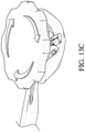
- Figs. 13A to 13D show steps of using the holder 100 according to one embodiment.
- Fig. 13A shows a side view of the holder 100 and a prosthetic replacement valve to be implanted.
- the valve has not yet been coupled to the holder 100 and the activator dial 110 is also uncoupled from the holder 100.
- the valve can be attached to the holder 100 via three sutures that connect the commissure posts of the valve to the body 102 and the rotor 104.
- one end of each of the sutures is connected to respective arms 114 of the body 102 and passed through respective ones of the commissure posts.
- Opposite ends of each of the sutures are routed through respective holes 120 of the body 102 and holes 130 in the rotor 104.
- the activator dial 110 is coupled to the holder 100 to adjust the configuration of the holder 100.
- the central shaft 131 of the activator dial 110 is placed inside the central opening 129 of the rotor 104 with key 137 of the dial 110 aligned and inserted through keyway 136a of the delivery mount 106.
- keyways 136a, 136b which minimize or prevent misuse of the holder 100.
- the keyways 136a, 136b enable the dial 110 to be preassembled with the holder 100 prior to use in surgical procedures, as described above.
- the activator dial 110 can then be rotated in the clockwise direction, for example, for almost one full rotation until the key 137 is aligned with keyway 136b.
- the holder 100 is moved into a deployed state whereby the commissure posts of the valve are pulled down and inwards towards the center of the holder 100, as shown in Fig. 13C .
- the valve is ready for insertion into a body, but the activator dial 110 remains connected to the holder 100 and prevents insertion of the valve into a small or minimally invasive incision due to the dial's 110 large size.
- the dial 110 While the activator dial 110 is connected, the dial 110 also prevents the handle 108 from being rotated to move the holder 100 into the second configuration for final implantation.
- the central shaft 331 is hollow and has an internal cavity (see Fig. 20 ), for example, to provide clearance for the sutures connected to inside of the rotor 304.
- the central shaft 331 can be inserted into the rotor 304 such that a bottom surface of the central shaft 331 is positioned adjacent or near a correspondence horizontal surface of the rotor 304.
- a lower portion of the central shaft 331 can include openings ( e.g., notches) 309 to aid with suture routing (see Fig. 20 ).
- the openings 309 can extend through the walls of the central shaft 331 and exposes the holes in the rotor 304 used to connect to the sutures.
- the guide 306 of the third embodiment provides ease of use and prevents misuse of the holder 300 during deployment.
- the guide 306 is positioned above the rotor 304 such that the dial 310 must pass through a central opening 316 of the guide 306 before the dial 310 can be connected to the rotor 304.
- the guide 306 includes a keyway 336 and a wall 344, which provide alignment for the activator dial 310 via a key or protrusion 337 on the central shaft 331 of the dial 310 ( see Figs. 18A and 18C ).
- the keyway 336 and the wall 344 of the guide 306 act as a stop that limits rotation of the dial 310 and the rotor 304 relative to body 302.
- the key 337 of the dial 310 may be positioned on a flexible arm 339 of the central shaft 331.
- the flexible arm 339 may be spaced apart from the remainder of the central shaft 331 by gaps 341 on either side of the flexible arm 339 such that the flexible arm 339 is movable ( e.g., bendable) relative to the remainder of the central shaft 331.
- the flexible arm 339 may be bent inwards relative to the remainder of the central shaft 331 and towards a cavity 343 of the dial 310.
- the flexible arm 339 may be resilient such that the flexible arm 339 may be bent by the application of a force and return to its original shape when the force is removed.
- the flexible arm 339 may be connected to an upper portion 345 of the dial 310.
- the dial 310 may be used in conjunction with the guide 306 to place the valve holder 300 in a deployed configuration as follows.
- the central shaft 331 of the dial 310 may be inserted into the central opening 316 of the guide 306 in an orientation such that the key 337 of the dial 310 is aligned with ( e.g., rotationally aligned with) a portion of the guide 306.
- the key 337 may be rotationally aligned with a marker 342 of the guide 306.
- the key 337 of the dial 310 extends from dial 310 with a length that is greater than the diameter of the central opening 316 of the guide 306.
- a lower surface 337b of the key 337 will contact an upper surface 332 of the guide 306. Due to the flexibility of the flexible arm 339 of the dial 310, contact between the key 337 of the dial 310 and the upper surface 332 of the guide 306 causes the flexible arm 339 to bend inwards into the cavity 343 such that the key 337 may pass through the central opening of the guide 306.
- the lower surface 337b of the key 337 has an oblique or slanted shape ( e.g., via a chamfer or fillet) relative to the upper surface 332 of the guide 306 to facilitate inward bending of the flexible arm 339 ( see Fig. 18C ).
- the flexible arm 339 returns to its original ( e.g., unbent) shape.
- An upper surface 337a of the key 337 has a flat shape that matches an underside surface 346 of the guide 306 to prevent or hinder the flexible arm 339 from bending once the key 337 passes the central opening 316 of the guide 306 (see Fig. 18C ). This is to retain the dial 310 in the guide 306 and prevent inadvertent or unintended removal of the dial 310 before deployment of the valve holder 300 is complete.
- the dial 310 may be rotated to cause the rotor 304 to rotate and deploy the valve, similarly described above with respect to the previous embodiments.
- the rotor 304 has a one-way ratcheting mechanism such that the dial 310 may only be rotated in one direction ( e.g., clockwise relative to the orientation shown in Figs. 18A and 19 ), and the dial 310 is prevented from being rotating in an opposite direction.
- the underside of the guide 306 has a channel or groove 348 to facilitate rotation of the dial 310 relative to guide 306, which provides clearance for the key 337 of the dial 310 during rotation.
- the channel 348 has a shape that encompasses a partial circumference of the guide 306. That is, the channel 348 has a circumference that is less than 360 degrees such that the activator dial 310 is restricted to less than one full rotation in use.
- the guide 306 additional has a wall 344 to prevent over-deployment or over-tightening of the valve.
- the wall 334 acts as a stop against the key 337 to limit further rotation of the dial 310 when the key 337 is rotated in the channel 348.
- the wall 344 is adjacent the keyway 336 of the guide 306 such that when the dial 310 has been fully rotated in the channel 348, the dial 310 may be removed by removing the key 337 upwards through the keyway 336.
- the keyway 336 is sized to permit the key 337 of the dial 310 to fit therethrough. Upon removal of the dial 310, the valve holder 300 is in the fully deployed configuration. In addition, the keyway 336 and the one-way ratcheting mechanism prevent under-deployment of the valve. The dial 310 is prevented or hindered from being removed from the guide 306 until the key 337 is aligned with the keyway 336.
- the guide 306 is positioned in a bore 311 of the body 302, and is coaxial with a central axis of the body 302 and the rotor 304.
- the guide 306 is positioned in the body 302 such that an upper surface 322 of the guide 306 is flush with or recessed relative to an upper surface 324 of the body 302.
- the guide 306 includes a generally circular-shaped central hub 314 with the central opening 316, and a plurality of arms 317 extending from the central hub 314.
- the central hub 314 may have other shapes ( e.g., triangular, square, rectangular, irregularly shaped, or otherwise shaped).
- the central opening 316 of the guide 306 is sized to permit the central shaft 331 of the activator dial to extend therethrough in order for the dial 310 to engage with the rotor 304 for deployment of the valve holder 300.
- the guide 306 may include the marker 342 for identifying a connection orientation of the guide 306 relative to the body 302. The marker 342 may be aligned with one of the arms 317.
- the arms 317 of the guide 306 are used to connect the guide 306 to the body 302.
- the guide 306 includes three arms 317, but can include more or fewer arms 317 in other embodiments.
- the arms 317 can extend from the guide 306 at approximately 120 degrees relative to each other.
- the body 302 includes a plurality of openings or channels 320 to connect the guide 306 to the body 302.
- the openings 320 of the body 302 can extend through the body 302 from the upper surface of the body 302 to a lower surface 326 of the body 302.
- the arms 317 of the guide 306 contain connection elements 328 that are designed to connect to the body 302 when the arms 317 are inserted into the openings 320 of the body 302.
- the connection elements 328 of the guide 306 may include flat surfaces that mate with ( e.g., abut) the lower surface 326 of the body 302.
- the arms 317 of the guide 306 may be resilient.
- the arms 317 may connect to the body 302 via a snap fit, press fit, or other connection.
- the guide 306 may be connected to the body 302 via a threaded engagement, and/or via pins or other fasteners or connection types.
- the delivery latch 308 is positioned on the guide 306, as shown in Fig. 20 , and is coaxial with the central axis of the body 302, the rotor 304, and the guide 306. In some embodiments, the delivery latch 308 is positioned on the upper surface 322 of the guide 306.
- the central opening 330 of the delivery latch 308 is sized to permit the stem 331 and key 337 of the dial 310 to be inserted into the opening 330 and pass through the latch 308, so that the stem 331 engages the ratchet mechanism of the body 302 and rotor 304, and so that the key 337 of the dial 310 engages the guide 306 as described above.
- the central opening 330 includes a generally circular cross section.
- the central opening 330 includes a generally circular cross section with a notch 332 for guiding the key 337 of the dial 310 through the delivery latch 308 at a particular rotational orientation, as shown in Figs. 18 , 20 , and 21 .
- the central opening 330 of the delivery latch 308 includes an engagement portion 334 to mate with a corresponding engagement feature 338 of the handle 305.
- the handle 305 is configured to be inserted into the central opening 330 of the latch 308 and removably coupled to the latch 308 for implantation.
- the engagement portion 334 of the latch 308 and the engagement feature 338 of the handle 305 include mating threads 334a, 338a.
- the opening 330 of the latch 308 can include a non-threaded lead-in portion 340 located adjacent the threads 334a.
- the mating threads 334a, 338a have, for example, from a #10-24 thread to a 7/16"-14 thread, or an M4 ⁇ 0.7 thread to an M12 ⁇ 1.75 thread.
- the delivery latch 308 of the third embodiment includes a guard 318 that is the same or similar to the guard 218 of the delivery mount 206 of the second embodiment.
- the guard 318 is located at a periphery of the delivery latch 308.
- Opposite to the guard are protrusions 319 for engaging horizontal openings 321 on the body 302.
- the guard 318 and protrusions 319 are used to connect the delivery latch 308 to the body 302.
- the guard 318 allows a single suture to connect the delivery latch 308 to the body 302, as described above for the delivery mount 206. Further, the guard 318 provides an additional safety feature against inadvertent or premature release of the valve from the holder 300.
- the guard 318 is aligned with the suture mount 312 of the body 302, and is positioned over and covers the suture mount 312, thereby preventing or reducing inadvertent or unintended cutting or breaking of the sutures connecting the holder 300 to the valve.
- the suture mount 312 is revealed and the suture or sutures connecting the valve holder 300 to the valve can then be cut or untied to release the valve.
- Assembly of the holder 300 is as follows. First, the rotor 304 is received in the body 302 similar to the second embodiment. Next, the guide 306 is coupled to the body 302 in position over the rotor 304. In particular, the arms 317 of the guide 306 are inserted into the openings 320 of the body 302. Next, one or more sutures are used to connect the holder 300 to the prosthetic valve, as described above with respect to the second embodiment. In some embodiments, the holder 300 may be connected to the prosthetic valve before the guide 306 is coupled to the body 302. Next the delivery latch 308 is coupled to the body 302 in position over the guide 306.
- the delivery latch 308 is coupled to the body 302 using one or more sutures, the guard 318, and the protrusions 319.
- the valve holder 300 is in position to be deployed using the activator dial 310, similarly as discussed with respect to the first and second embodiments.
- the activator dial 310 is inserted into the central opening 330 of the latch 308, passed through the latch 308 and the guide 306, and connected to the rotor 304.
- the activator dial 308 is rotated to deploy the valve holder 300, and is then removed from the holder 300.
- the handle 305 can be inserted into and connected to the latch 308 for insertion and implantation of the attached valve into a patient.
- the assembly sequence can be varied to achieve the same or similar assembled combinations.
- valve holder various different features from the different embodiments discussed above can also be combined into a single modified valve holder.
- various other modifications or alternative configurations can also be made to the valve holder according to the above described embodiments.
- the presented embodiments also include an introducer which aids in delivering valve holders in minimally invasive surgical procedures.
- the introducer can be used with collapsible surgical valves to introduce the valves into a narrow surgical incision, such as a thoracotomy.
- the introducer can be used, for example, for delivering a prosthetic mitral valve to the mitral position.
- the introducer has a funnel-like shape for passing a collapsible heart valve from outside the body to inside the body through a narrow opening, such as the space between two ribs.
- an incision is introduced into the chest cavity through the chest wall.
- the incision is made between adjacent ribs to minimize cuts through bone, nerves, and muscle.
- the distance between the ribs, without spreading the ribs is from about 15 mm to about 20 mm.
- the incision can be longer as needed, for example, approximately 45 mm or greater.
- Collapsible valve holders can have a small size that is particularly suited to fit in the small gap between the ribs in thoracotomy procedures.
- Figs. 25 to 26 show views of an introducer 400 for introducing a valve and holder into a human body according to another embodiment.
- the introducer 400 provides a simple alternative approach for implanting collapsible heart valves connected to flexible holders through a minimal size incision, such as in a thoracotomy procedure. Due to the small gap between human ribs, the introducer 400 is used as an aid for inserting valves mounted on alternative flexible holders past the ribs and into the chest cavity during a thoracotomy or other minimally invasive procedures.
- the cross-section of the proximal end 402 is 45 mm in diameter.
- the distal end 404 has an oval cross-sectional shape corresponding to a size and shape of a surgical opening between ribs in a thoracotomy procedure.
- the major diameter of the cross section of the distal end 404 is about 45 mm in diameter and the minor diameter of the cross section is from about 15 mm to about 20 mm in diameter.
- the introducer 400 includes a smooth transition zone or region 406 connecting the ends 402, 404.
- the transition region 406 may have a smooth, continuous inner profile between the ends 402, 404, which is substantially free from corners.
- the introducer 400 can be made very inexpensively as a disposable item that is supplied with a valve.
- the introducer 400 can be made of or include polypropylene, or any other suitable material having a low coefficient of friction.
- the introducer 400 can be a molded part.
- the valve to be implanted can be made of a Nitinol wireform band exhibiting a large degree of elasticity. In one embodiment, the valve exhibits superelastic properties.
- the introducer 400 can include various additional features, for example, a slit in a wall of the introducer 400 can be provided to give clearance for sutures passing through a side of the introducer during surgical procedures.
- lighting such as light emitting diodes ("LEDs") and/or at least one optical fiber, can be added to the introducer, along with a power supply, such as batteries, to power the lighting.
- LED lighting can be inexpensively added to the introducer with a built-in battery.
- the lighting can be particularly useful with the extended version of the introducer.
- the lighting can provide excellent illumination at the site of implantation and reduce the need for additional external lighting.
Landscapes
- Health & Medical Sciences (AREA)
- Cardiology (AREA)
- Life Sciences & Earth Sciences (AREA)
- Engineering & Computer Science (AREA)
- Biomedical Technology (AREA)
- Veterinary Medicine (AREA)
- Heart & Thoracic Surgery (AREA)
- Animal Behavior & Ethology (AREA)
- General Health & Medical Sciences (AREA)
- Public Health (AREA)
- Vascular Medicine (AREA)
- Transplantation (AREA)
- Oral & Maxillofacial Surgery (AREA)
- Surgery (AREA)
- Nuclear Medicine, Radiotherapy & Molecular Imaging (AREA)
- Medical Informatics (AREA)
- Molecular Biology (AREA)
- Prostheses (AREA)
Applications Claiming Priority (5)
| Application Number | Priority Date | Filing Date | Title |
|---|---|---|---|
| US201662417207P | 2016-11-03 | 2016-11-03 | |
| US15/796,147 US10722356B2 (en) | 2016-11-03 | 2017-10-27 | Prosthetic mitral valve holders |
| EP20202691.0A EP3799836B1 (de) | 2016-11-03 | 2017-11-03 | Halter von prothetischen mitralklappen |
| EP17890416.5A EP3534845B1 (de) | 2016-11-03 | 2017-11-03 | Halter von prothetischen mitralklappen |
| PCT/US2017/060025 WO2018128693A2 (en) | 2016-11-03 | 2017-11-03 | Prosthetic mitral valve holders |
Related Parent Applications (2)
| Application Number | Title | Priority Date | Filing Date |
|---|---|---|---|
| EP20202691.0A Division EP3799836B1 (de) | 2016-11-03 | 2017-11-03 | Halter von prothetischen mitralklappen |
| EP17890416.5A Division EP3534845B1 (de) | 2016-11-03 | 2017-11-03 | Halter von prothetischen mitralklappen |
Publications (2)
| Publication Number | Publication Date |
|---|---|
| EP4582056A2 true EP4582056A2 (de) | 2025-07-09 |
| EP4582056A3 EP4582056A3 (de) | 2025-09-24 |
Family
ID=62020740
Family Applications (3)
| Application Number | Title | Priority Date | Filing Date |
|---|---|---|---|
| EP17890416.5A Active EP3534845B1 (de) | 2016-11-03 | 2017-11-03 | Halter von prothetischen mitralklappen |
| EP25157107.1A Pending EP4582056A3 (de) | 2016-11-03 | 2017-11-03 | Halter für prothetische mitralklappe |
| EP20202691.0A Active EP3799836B1 (de) | 2016-11-03 | 2017-11-03 | Halter von prothetischen mitralklappen |
Family Applications Before (1)
| Application Number | Title | Priority Date | Filing Date |
|---|---|---|---|
| EP17890416.5A Active EP3534845B1 (de) | 2016-11-03 | 2017-11-03 | Halter von prothetischen mitralklappen |
Family Applications After (1)
| Application Number | Title | Priority Date | Filing Date |
|---|---|---|---|
| EP20202691.0A Active EP3799836B1 (de) | 2016-11-03 | 2017-11-03 | Halter von prothetischen mitralklappen |
Country Status (6)
| Country | Link |
|---|---|
| US (8) | US10722356B2 (de) |
| EP (3) | EP3534845B1 (de) |
| CN (1) | CN109922757B (de) |
| CA (1) | CA3042266C (de) |
| ES (1) | ES2844748T3 (de) |
| WO (1) | WO2018128693A2 (de) |
Families Citing this family (24)
| Publication number | Priority date | Publication date | Assignee | Title |
|---|---|---|---|---|
| US8057538B2 (en) * | 2005-02-18 | 2011-11-15 | Medtronic, Inc. | Valve holder |
| US8579964B2 (en) | 2010-05-05 | 2013-11-12 | Neovasc Inc. | Transcatheter mitral valve prosthesis |
| US9554897B2 (en) | 2011-04-28 | 2017-01-31 | Neovasc Tiara Inc. | Methods and apparatus for engaging a valve prosthesis with tissue |
| US9308087B2 (en) | 2011-04-28 | 2016-04-12 | Neovasc Tiara Inc. | Sequentially deployed transcatheter mitral valve prosthesis |
| US9345573B2 (en) | 2012-05-30 | 2016-05-24 | Neovasc Tiara Inc. | Methods and apparatus for loading a prosthesis onto a delivery system |
| US9572665B2 (en) | 2013-04-04 | 2017-02-21 | Neovasc Tiara Inc. | Methods and apparatus for delivering a prosthetic valve to a beating heart |
| CN108601645B (zh) | 2015-12-15 | 2021-02-26 | 内奥瓦斯克迪亚拉公司 | 经中隔递送系统 |
| DE112017000541T5 (de) | 2016-01-29 | 2018-10-18 | Neovasc Tiara Inc. | Klappenprothese zum verhindern einer abflussobstruktion |
| US10722356B2 (en) | 2016-11-03 | 2020-07-28 | Edwards Lifesciences Corporation | Prosthetic mitral valve holders |
| CA3042588A1 (en) | 2016-11-21 | 2018-05-24 | Neovasc Tiara Inc. | Methods and systems for rapid retraction of a transcatheter heart valve delivery system |
| CA3060663C (en) * | 2017-04-28 | 2024-03-26 | Edwards Lifesciences Corporation | Prosthetic heart valve with collapsible holder |
| CN111263622A (zh) | 2017-08-25 | 2020-06-09 | 内奥瓦斯克迪亚拉公司 | 顺序展开的经导管二尖瓣假体 |
| US12059347B2 (en) * | 2018-08-06 | 2024-08-13 | Corcym S.R.L. | Tiltable tools for heart valve prosthesis |
| WO2020092422A1 (en) | 2018-11-01 | 2020-05-07 | Edwards Lifesciences Corporation | Annuloplasty ring assembly with detachable handle |
| CN113164256B (zh) * | 2018-11-01 | 2024-04-16 | 爱德华兹生命科学公司 | 用于心脏瓣膜修复和置换的带有致动器的植入物保持器组合件 |
| JP7260930B2 (ja) | 2018-11-08 | 2023-04-19 | ニオバスク ティアラ インコーポレイテッド | 経カテーテル僧帽弁人工補綴物の心室展開 |
| CN113747863B (zh) | 2019-03-08 | 2024-11-08 | 内奥瓦斯克迪亚拉公司 | 可取回假体递送系统 |
| CA3135753C (en) | 2019-04-01 | 2023-10-24 | Neovasc Tiara Inc. | Controllably deployable prosthetic valve |
| AU2020271896B2 (en) | 2019-04-10 | 2022-10-13 | Neovasc Tiara Inc. | Prosthetic valve with natural blood flow |
| AU2020279750B2 (en) | 2019-05-20 | 2023-07-13 | Neovasc Tiara Inc. | Introducer with hemostasis mechanism |
| CN114144144B (zh) | 2019-06-20 | 2026-01-13 | 内奥瓦斯克迪亚拉公司 | 低轮廓假体二尖瓣 |
| CR20210655A (es) | 2019-12-16 | 2022-06-02 | Edwards Lifesciences Corp | Conjunto de soporte de válvula con protección de bucle de sutura |
| US12156812B2 (en) | 2021-05-05 | 2024-12-03 | St. Jude Medical, Cardiology Division, Inc. | Apparatus and methods for a prosthetic mitral valve holder |
| US11872129B2 (en) | 2021-10-07 | 2024-01-16 | Jilin Venus Haoyue Medtech Limited | System and method for holding and delivering a surgical heart valve |
Family Cites Families (112)
| Publication number | Priority date | Publication date | Assignee | Title |
|---|---|---|---|---|
| DE1566384A1 (de) * | 1966-05-04 | 1970-04-30 | Shiley Donald Pearce | Prothese |
| NL143127B (nl) | 1969-02-04 | 1974-09-16 | Rhone Poulenc Sa | Versterkingsorgaan voor een defecte hartklep. |
| FR2298313A1 (fr) | 1975-06-23 | 1976-08-20 | Usifroid | Reducteur lineaire pour valvuloplastie |
| US4164046A (en) | 1977-05-16 | 1979-08-14 | Cooley Denton | Valve prosthesis |
| US4865600A (en) | 1981-08-25 | 1989-09-12 | Baxter International Inc. | Mitral valve holder |
| DE3230858C2 (de) | 1982-08-19 | 1985-01-24 | Ahmadi, Ali, Dr. med., 7809 Denzlingen | Ringprothese |
| US4801015A (en) * | 1986-04-16 | 1989-01-31 | Shiley Inc. | Releasable holder and package assembly for a prosthetic heart valve |
| CA1303298C (en) | 1986-08-06 | 1992-06-16 | Alain Carpentier | Flexible cardiac valvular support prosthesis |
| IT1218951B (it) | 1988-01-12 | 1990-04-24 | Mario Morea | Dispositivo protesico per la correzione chirurgica dell'insufficenza tricuspidale |
| DE69033195T2 (de) | 1989-02-13 | 2000-03-09 | Baxter International Inc. | Ringprothese für Anuloplastie |
| US5290300A (en) | 1989-07-31 | 1994-03-01 | Baxter International Inc. | Flexible suture guide and holder |
| US5041130A (en) | 1989-07-31 | 1991-08-20 | Baxter International Inc. | Flexible annuloplasty ring and holder |
| US5037434A (en) * | 1990-04-11 | 1991-08-06 | Carbomedics, Inc. | Bioprosthetic heart valve with elastic commissures |
| US5064431A (en) | 1991-01-16 | 1991-11-12 | St. Jude Medical Incorporated | Annuloplasty ring |
| WO1993002640A1 (en) | 1991-08-02 | 1993-02-18 | Baxter International Inc. | Flexible suture guide and holder |
| US5306296A (en) | 1992-08-21 | 1994-04-26 | Medtronic, Inc. | Annuloplasty and suture rings |
| US5201880A (en) | 1992-01-27 | 1993-04-13 | Pioneering Technologies, Inc. | Mitral and tricuspid annuloplasty rings |
| US5258021A (en) | 1992-01-27 | 1993-11-02 | Duran Carlos G | Sigmoid valve annuloplasty ring |
| JP2002509448A (ja) | 1992-01-27 | 2002-03-26 | メドトロニック インコーポレーテッド | 輪状形成及び縫合リング |
| US5972030A (en) | 1993-02-22 | 1999-10-26 | Heartport, Inc. | Less-invasive devices and methods for treatment of cardiac valves |
| FR2708458B1 (fr) | 1993-08-03 | 1995-09-15 | Seguin Jacques | Anneau prothétique pour chirurgie cardiaque. |
| US5593435A (en) | 1994-07-29 | 1997-01-14 | Baxter International Inc. | Distensible annuloplasty ring for surgical remodelling of an atrioventricular valve and nonsurgical method for post-implantation distension thereof to accommodate patient growth |
| US6217610B1 (en) | 1994-07-29 | 2001-04-17 | Edwards Lifesciences Corporation | Expandable annuloplasty ring |
| US5776187A (en) | 1995-02-09 | 1998-07-07 | St. Jude Medical, Inc. | Combined holder tool and rotator for a prosthetic heart valve |
| USD372781S (en) * | 1995-03-24 | 1996-08-13 | Tri Technologies Inc. | Heart valve rotator |
| EP0869751A1 (de) | 1995-11-01 | 1998-10-14 | St. Jude Medical, Inc. | Bioresorbierbare prothese für annuloplastie |
| EP0871417B1 (de) | 1995-12-01 | 2003-10-01 | Medtronic, Inc. | Prothese für anuloplastie |
| US5800531A (en) | 1996-09-30 | 1998-09-01 | Baxter International Inc. | Bioprosthetic heart valve implantation device |
| US7883539B2 (en) | 1997-01-02 | 2011-02-08 | Edwards Lifesciences Llc | Heart wall tension reduction apparatus and method |
| US5776189A (en) | 1997-03-05 | 1998-07-07 | Khalid; Naqeeb | Cardiac valvular support prosthesis |
| US6332893B1 (en) | 1997-12-17 | 2001-12-25 | Myocor, Inc. | Valve to myocardium tension members device and method |
| US6001127A (en) | 1998-03-31 | 1999-12-14 | St. Jude Medical, Inc. | Annuloplasty ring holder |
| US6143024A (en) | 1998-06-04 | 2000-11-07 | Sulzer Carbomedics Inc. | Annuloplasty ring having flexible anterior portion |
| US6250308B1 (en) | 1998-06-16 | 2001-06-26 | Cardiac Concepts, Inc. | Mitral valve annuloplasty ring and method of implanting |
| US6159240A (en) | 1998-08-31 | 2000-12-12 | Medtronic, Inc. | Rigid annuloplasty device that becomes compliant after implantation |
| US6102945A (en) | 1998-10-16 | 2000-08-15 | Sulzer Carbomedics, Inc. | Separable annuloplasty ring |
| DE19910233A1 (de) | 1999-03-09 | 2000-09-21 | Jostra Medizintechnik Ag | Anuloplastieprothese |
| US6231602B1 (en) | 1999-04-16 | 2001-05-15 | Edwards Lifesciences Corporation | Aortic annuloplasty ring |
| US6183512B1 (en) | 1999-04-16 | 2001-02-06 | Edwards Lifesciences Corporation | Flexible annuloplasty system |
| US6187040B1 (en) | 1999-05-03 | 2001-02-13 | John T. M. Wright | Mitral and tricuspid annuloplasty rings |
| US6602289B1 (en) | 1999-06-08 | 2003-08-05 | S&A Rings, Llc | Annuloplasty rings of particular use in surgery for the mitral valve |
| US6319280B1 (en) | 1999-08-03 | 2001-11-20 | St. Jude Medical, Inc. | Prosthetic ring holder |
| CA2399905C (en) | 2000-01-14 | 2008-11-18 | Viacor Incorporated | An annuloplasty band |
| US6402781B1 (en) | 2000-01-31 | 2002-06-11 | Mitralife | Percutaneous mitral annuloplasty and cardiac reinforcement |
| US6797002B2 (en) | 2000-02-02 | 2004-09-28 | Paul A. Spence | Heart valve repair apparatus and methods |
| US6419698B1 (en) | 2000-04-03 | 2002-07-16 | Paul T. Finger | Orbital implant device |
| US6419695B1 (en) | 2000-05-22 | 2002-07-16 | Shlomo Gabbay | Cardiac prosthesis for helping improve operation of a heart valve |
| US6406493B1 (en) | 2000-06-02 | 2002-06-18 | Hosheng Tu | Expandable annuloplasty ring and methods of use |
| US6805711B2 (en) | 2000-06-02 | 2004-10-19 | 3F Therapeutics, Inc. | Expandable medical implant and percutaneous delivery |
| DE10030410C1 (de) | 2000-06-21 | 2002-01-24 | Roche Diagnostics Gmbh | Blutlanzettenvorrichtung zur Entnahme von Blut für Diagnosezwecke |
| US6602288B1 (en) | 2000-10-05 | 2003-08-05 | Edwards Lifesciences Corporation | Minimally-invasive annuloplasty repair segment delivery template, system and method of use |
| US6918917B1 (en) | 2000-10-10 | 2005-07-19 | Medtronic, Inc. | Minimally invasive annuloplasty procedure and apparatus |
| US6966925B2 (en) * | 2000-12-21 | 2005-11-22 | Edwards Lifesciences Corporation | Heart valve holder and method for resisting suture looping |
| US6955689B2 (en) | 2001-03-15 | 2005-10-18 | Medtronic, Inc. | Annuloplasty band and method |
| US6619291B2 (en) | 2001-04-24 | 2003-09-16 | Edwin J. Hlavka | Method and apparatus for catheter-based annuloplasty |
| US6800090B2 (en) | 2001-05-14 | 2004-10-05 | Cardiac Dimensions, Inc. | Mitral valve therapy device, system and method |
| US6858039B2 (en) | 2002-07-08 | 2005-02-22 | Edwards Lifesciences Corporation | Mitral valve annuloplasty ring having a posterior bow |
| ITMI20011012A1 (it) | 2001-05-17 | 2002-11-17 | Ottavio Alfieri | Protesi anulare per valvola mitrale |
| US7935145B2 (en) | 2001-05-17 | 2011-05-03 | Edwards Lifesciences Corporation | Annuloplasty ring for ischemic mitral valve insuffuciency |
| US6726716B2 (en) | 2001-08-24 | 2004-04-27 | Edwards Lifesciences Corporation | Self-molding annuloplasty ring |
| US6908482B2 (en) | 2001-08-28 | 2005-06-21 | Edwards Lifesciences Corporation | Three-dimensional annuloplasty ring and template |
| WO2003020179A1 (en) | 2001-08-31 | 2003-03-13 | Mitral Interventions | Apparatus for valve repair |
| US20060020336A1 (en) | 2001-10-23 | 2006-01-26 | Liddicoat John R | Automated annular plication for mitral valve repair |
| US6949122B2 (en) | 2001-11-01 | 2005-09-27 | Cardiac Dimensions, Inc. | Focused compression mitral valve device and method |
| US6805710B2 (en) | 2001-11-13 | 2004-10-19 | Edwards Lifesciences Corporation | Mitral valve annuloplasty ring for molding left ventricle geometry |
| US7033390B2 (en) | 2002-01-02 | 2006-04-25 | Medtronic, Inc. | Prosthetic heart valve system |
| US6764510B2 (en) | 2002-01-09 | 2004-07-20 | Myocor, Inc. | Devices and methods for heart valve treatment |
| US6719786B2 (en) | 2002-03-18 | 2004-04-13 | Medtronic, Inc. | Flexible annuloplasty prosthesis and holder |
| US7118595B2 (en) | 2002-03-18 | 2006-10-10 | Medtronic, Inc. | Flexible annuloplasty prosthesis and holder |
| EP1521550A4 (de) | 2002-06-12 | 2011-02-23 | Mitral Interventions Inc | Verfahren und vorrichtung für eine gewebeverbindung |
| AU2003245507A1 (en) | 2002-06-13 | 2003-12-31 | Guided Delivery Systems, Inc. | Devices and methods for heart valve repair |
| US6966924B2 (en) | 2002-08-16 | 2005-11-22 | St. Jude Medical, Inc. | Annuloplasty ring holder |
| US7175660B2 (en) | 2002-08-29 | 2007-02-13 | Mitralsolutions, Inc. | Apparatus for implanting surgical devices for controlling the internal circumference of an anatomic orifice or lumen |
| US7087064B1 (en) | 2002-10-15 | 2006-08-08 | Advanced Cardiovascular Systems, Inc. | Apparatuses and methods for heart valve repair |
| US7431726B2 (en) | 2003-12-23 | 2008-10-07 | Mitralign, Inc. | Tissue fastening systems and methods utilizing magnetic guidance |
| US7294148B2 (en) | 2004-04-29 | 2007-11-13 | Edwards Lifesciences Corporation | Annuloplasty ring for mitral valve prolapse |
| US20050256568A1 (en) | 2004-05-14 | 2005-11-17 | St. Jude Medical, Inc. | C-shaped heart valve prostheses |
| WO2005112832A1 (en) | 2004-05-14 | 2005-12-01 | St. Jude Medical, Inc. | Systems and methods for holding annuloplasty rings |
| US7938856B2 (en) | 2004-05-14 | 2011-05-10 | St. Jude Medical, Inc. | Heart valve annuloplasty prosthesis sewing cuffs and methods of making same |
| US20050278022A1 (en) | 2004-06-14 | 2005-12-15 | St. Jude Medical, Inc. | Annuloplasty prostheses with improved anchoring structures, and related methods |
| WO2006019943A1 (en) | 2004-07-15 | 2006-02-23 | Micardia Corporation | Implants and methods for reshaping heart valves |
| US8034102B2 (en) | 2004-07-19 | 2011-10-11 | Coroneo, Inc. | Aortic annuloplasty ring |
| JP2008506497A (ja) * | 2004-07-19 | 2008-03-06 | セント ジュード メディカル インコーポレイテッド | 心臓弁の支持体および蓋裏打ちシステムならびに方法 |
| US8012202B2 (en) | 2004-07-27 | 2011-09-06 | Alameddine Abdallah K | Mitral valve ring for treatment of mitral valve regurgitation |
| CN2782049Y (zh) * | 2005-01-21 | 2006-05-24 | 金磊 | 瓣膜成形环持环器 |
| US8057538B2 (en) * | 2005-02-18 | 2011-11-15 | Medtronic, Inc. | Valve holder |
| US20070162111A1 (en) | 2005-07-06 | 2007-07-12 | The Cleveland Clinic Foundation | Apparatus and method for replacing a cardiac valve |
| WO2007035882A2 (en) | 2005-09-21 | 2007-03-29 | Genesee Biomedical, Inc. | Annuloplasty ring holder |
| WO2007072399A1 (en) | 2005-12-19 | 2007-06-28 | Robert William Mayo Frater | Annuloplasty prosthesis |
| US20070179602A1 (en) * | 2006-01-27 | 2007-08-02 | Genesee Biomedical, Inc. | Method and Devices For Cardiac Valve Annulus Expansion |
| US8454684B2 (en) * | 2006-08-02 | 2013-06-04 | Medtronic, Inc. | Heart valve holder for use in valve implantation procedures |
| US9333076B1 (en) * | 2007-05-24 | 2016-05-10 | St. Jude Medical, Inc. | Prosthetic heart valve holder apparatus |
| EP2420205B1 (de) * | 2007-06-26 | 2014-04-09 | St. Jude Medical, Inc. | Vorrichtung zur Implantation falt- und dehnbarer Herzklappenprothesen |
| US8273118B2 (en) * | 2007-09-17 | 2012-09-25 | Medtronic, Inc. | Heart valve holder assembly for use in valve implantation procedures |
| US20090259305A1 (en) * | 2008-04-12 | 2009-10-15 | Fred Lane | Implantable Prosthetic Holder and Handle |
| US20090132034A1 (en) * | 2007-11-15 | 2009-05-21 | Fernando Riveron | Bioprosthetic Valve Clip and Handle |
| US7993395B2 (en) | 2008-01-25 | 2011-08-09 | Medtronic, Inc. | Set of annuloplasty devices with varying anterior-posterior ratios and related methods |
| US20090192603A1 (en) | 2008-01-25 | 2009-07-30 | Medtronic, Inc. | Adjustable Sizer Devices for Minimally Invasive Cardiac Surgery |
| US8152844B2 (en) | 2008-05-09 | 2012-04-10 | Edwards Lifesciences Corporation | Quick-release annuloplasty ring holder |
| US8869982B2 (en) * | 2009-12-18 | 2014-10-28 | Edwards Lifesciences Corporation | Prosthetic heart valve packaging and deployment system |
| SE535140C2 (sv) * | 2010-03-25 | 2012-04-24 | Jan Otto Solem | En implanterbar anordning, kit och system för förbättring av hjärtfunktionen, innefattande medel för generering av longitudinell rörelse av mitralisklaffen |
| US8986374B2 (en) * | 2010-05-10 | 2015-03-24 | Edwards Lifesciences Corporation | Prosthetic heart valve |
| US9078750B2 (en) | 2010-11-30 | 2015-07-14 | Edwards Lifesciences Corporation | Ergonomic mitral heart valve holders |
| US9498317B2 (en) * | 2010-12-16 | 2016-11-22 | Edwards Lifesciences Corporation | Prosthetic heart valve delivery systems and packaging |
| CN104523353B (zh) * | 2014-12-24 | 2016-10-12 | 金仕生物科技(常熟)有限公司 | 人工二尖瓣瓣膜持瓣器 |
| CN204468345U (zh) * | 2015-01-15 | 2015-07-15 | 金仕生物科技(常熟)有限公司 | 人工心脏瓣膜成形环持环器 |
| USD827134S1 (en) * | 2015-08-13 | 2018-08-28 | Medical Pine Co., Ltd. | Sizer for cardiac valve ring and blood vessel diameter |
| US10722356B2 (en) * | 2016-11-03 | 2020-07-28 | Edwards Lifesciences Corporation | Prosthetic mitral valve holders |
| USD846122S1 (en) * | 2016-12-16 | 2019-04-16 | Edwards Lifesciences Corporation | Heart valve sizer |
| US12083013B2 (en) * | 2017-10-07 | 2024-09-10 | Corcym S.R.L. | Bendable cardiac surgery instruments |
| USD921895S1 (en) * | 2019-07-09 | 2021-06-08 | Cilag Gmbh International | Esophagus sizing instrument |
| USD952848S1 (en) * | 2020-11-05 | 2022-05-24 | Shukla Medical | Measurement guide for an acetabular cup extractor |
-
2017
- 2017-10-27 US US15/796,147 patent/US10722356B2/en active Active
- 2017-11-03 WO PCT/US2017/060025 patent/WO2018128693A2/en not_active Ceased
- 2017-11-03 CA CA3042266A patent/CA3042266C/en active Active
- 2017-11-03 EP EP17890416.5A patent/EP3534845B1/de active Active
- 2017-11-03 EP EP25157107.1A patent/EP4582056A3/de active Pending
- 2017-11-03 ES ES17890416T patent/ES2844748T3/es active Active
- 2017-11-03 EP EP20202691.0A patent/EP3799836B1/de active Active
- 2017-11-03 CN CN201780067851.XA patent/CN109922757B/zh active Active
-
2018
- 2018-04-24 US US29/645,199 patent/USD933229S1/en active Active
-
2020
- 2020-07-22 US US16/936,364 patent/US11717404B2/en active Active
-
2021
- 2021-10-08 US US29/810,899 patent/USD960372S1/en active Active
-
2022
- 2022-08-05 US US29/865,663 patent/USD1112743S1/en active Active
-
2023
- 2023-05-26 US US29/876,771 patent/USD1043986S1/en active Active
- 2023-08-04 US US18/365,900 patent/US12440330B2/en active Active
-
2025
- 2025-09-22 US US19/335,572 patent/US20260013986A1/en active Pending
Also Published As
| Publication number | Publication date |
|---|---|
| US20200345491A1 (en) | 2020-11-05 |
| EP3534845B1 (de) | 2020-10-21 |
| EP3799836B1 (de) | 2025-02-12 |
| EP3534845A2 (de) | 2019-09-11 |
| USD1043986S1 (en) | 2024-09-24 |
| USD960372S1 (en) | 2022-08-09 |
| EP3799836A1 (de) | 2021-04-07 |
| USD933229S1 (en) | 2021-10-12 |
| CN109922757A (zh) | 2019-06-21 |
| US12440330B2 (en) | 2025-10-14 |
| CN109922757B (zh) | 2021-05-28 |
| US20230372094A1 (en) | 2023-11-23 |
| US20260013986A1 (en) | 2026-01-15 |
| CA3042266C (en) | 2023-03-28 |
| WO2018128693A3 (en) | 2018-09-07 |
| EP3534845A4 (de) | 2019-11-06 |
| WO2018128693A2 (en) | 2018-07-12 |
| CA3042266A1 (en) | 2018-07-12 |
| ES2844748T3 (es) | 2021-07-22 |
| US11717404B2 (en) | 2023-08-08 |
| US10722356B2 (en) | 2020-07-28 |
| EP4582056A3 (de) | 2025-09-24 |
| EP3799836C0 (de) | 2025-02-12 |
| USD1112743S1 (en) | 2026-02-10 |
| US20180116795A1 (en) | 2018-05-03 |
Similar Documents
| Publication | Publication Date | Title |
|---|---|---|
| US12440330B2 (en) | Prosthetic mitral valve holders | |
| US12419742B2 (en) | Method for delivering a surgical heart valve | |
| US12491071B2 (en) | Prosthetic heart valve with collapsible holder | |
| US20220331100A1 (en) | Prosthetic valve holders with automatic deploying mechanisms | |
| HK40049418A (en) | Prosthetic mitral valve holders | |
| HK40049418B (en) | Prosthetic mitral valve holders | |
| HK40009401A (en) | Prosthetic mitral valve holders | |
| HK40009401B (zh) | 假体二尖瓣保持器 | |
| CN113164256A (zh) | 用于心脏瓣膜修复和置换的带有致动器的植入物保持器组合件 |
Legal Events
| Date | Code | Title | Description |
|---|---|---|---|
| PUAI | Public reference made under article 153(3) epc to a published international application that has entered the european phase |
Free format text: ORIGINAL CODE: 0009012 |
|
| STAA | Information on the status of an ep patent application or granted ep patent |
Free format text: STATUS: THE APPLICATION HAS BEEN PUBLISHED |
|
| AC | Divisional application: reference to earlier application |
Ref document number: 3534845 Country of ref document: EP Kind code of ref document: P Ref document number: 3799836 Country of ref document: EP Kind code of ref document: P |
|
| AK | Designated contracting states |
Kind code of ref document: A2 Designated state(s): AL AT BE BG CH CY CZ DE DK EE ES FI FR GB GR HR HU IE IS IT LI LT LU LV MC MK MT NL NO PL PT RO RS SE SI SK SM TR |
|
| PUAL | Search report despatched |
Free format text: ORIGINAL CODE: 0009013 |
|
| P01 | Opt-out of the competence of the unified patent court (upc) registered |
Free format text: CASE NUMBER: UPC_APP_2862_4582056/2025 Effective date: 20250808 |
|
| AK | Designated contracting states |
Kind code of ref document: A3 Designated state(s): AL AT BE BG CH CY CZ DE DK EE ES FI FR GB GR HR HU IE IS IT LI LT LU LV MC MK MT NL NO PL PT RO RS SE SI SK SM TR |
|
| RIC1 | Information provided on ipc code assigned before grant |
Ipc: A61F 2/24 20060101AFI20250819BHEP |