EP4582012A2 - Verrous d'actionneur de dispositif médical - Google Patents
Verrous d'actionneur de dispositif médical Download PDFInfo
- Publication number
- EP4582012A2 EP4582012A2 EP25172452.2A EP25172452A EP4582012A2 EP 4582012 A2 EP4582012 A2 EP 4582012A2 EP 25172452 A EP25172452 A EP 25172452A EP 4582012 A2 EP4582012 A2 EP 4582012A2
- Authority
- EP
- European Patent Office
- Prior art keywords
- handle
- bar
- cross
- actuator
- teeth
- Prior art date
- Legal status (The legal status is an assumption and is not a legal conclusion. Google has not performed a legal analysis and makes no representation as to the accuracy of the status listed.)
- Pending
Links
Images


Classifications
-
- A—HUMAN NECESSITIES
- A61—MEDICAL OR VETERINARY SCIENCE; HYGIENE
- A61B—DIAGNOSIS; SURGERY; IDENTIFICATION
- A61B1/00—Instruments for performing medical examinations of the interior of cavities or tubes of the body by visual or photographical inspection, e.g. endoscopes; Illuminating arrangements therefor
- A61B1/005—Flexible endoscopes
- A61B1/0051—Flexible endoscopes with controlled bending of insertion part
- A61B1/0052—Constructional details of control elements, e.g. handles
-
- A—HUMAN NECESSITIES
- A61—MEDICAL OR VETERINARY SCIENCE; HYGIENE
- A61B—DIAGNOSIS; SURGERY; IDENTIFICATION
- A61B1/00—Instruments for performing medical examinations of the interior of cavities or tubes of the body by visual or photographical inspection, e.g. endoscopes; Illuminating arrangements therefor
- A61B1/00064—Constructional details of the endoscope body
- A61B1/00066—Proximal part of endoscope body, e.g. handles
-
- A—HUMAN NECESSITIES
- A61—MEDICAL OR VETERINARY SCIENCE; HYGIENE
- A61B—DIAGNOSIS; SURGERY; IDENTIFICATION
- A61B1/00—Instruments for performing medical examinations of the interior of cavities or tubes of the body by visual or photographical inspection, e.g. endoscopes; Illuminating arrangements therefor
- A61B1/00002—Operational features of endoscopes
- A61B1/00039—Operational features of endoscopes provided with input arrangements for the user
- A61B1/00042—Operational features of endoscopes provided with input arrangements for the user for mechanical operation
-
- A—HUMAN NECESSITIES
- A61—MEDICAL OR VETERINARY SCIENCE; HYGIENE
- A61B—DIAGNOSIS; SURGERY; IDENTIFICATION
- A61B1/00—Instruments for performing medical examinations of the interior of cavities or tubes of the body by visual or photographical inspection, e.g. endoscopes; Illuminating arrangements therefor
- A61B1/00064—Constructional details of the endoscope body
- A61B1/00071—Insertion part of the endoscope body
- A61B1/0008—Insertion part of the endoscope body characterised by distal tip features
- A61B1/00098—Deflecting means for inserted tools
-
- A—HUMAN NECESSITIES
- A61—MEDICAL OR VETERINARY SCIENCE; HYGIENE
- A61B—DIAGNOSIS; SURGERY; IDENTIFICATION
- A61B1/00—Instruments for performing medical examinations of the interior of cavities or tubes of the body by visual or photographical inspection, e.g. endoscopes; Illuminating arrangements therefor
- A61B1/273—Instruments for performing medical examinations of the interior of cavities or tubes of the body by visual or photographical inspection, e.g. endoscopes; Illuminating arrangements therefor for the upper alimentary canal, e.g. oesophagoscopes, gastroscopes
-
- G—PHYSICS
- G05—CONTROLLING; REGULATING
- G05G—CONTROL DEVICES OR SYSTEMS INSOFAR AS CHARACTERISED BY MECHANICAL FEATURES ONLY
- G05G5/00—Means for preventing, limiting or returning the movements of parts of a control mechanism, e.g. locking controlling member
- G05G5/06—Means for preventing, limiting or returning the movements of parts of a control mechanism, e.g. locking controlling member for holding members in one or a limited number of definite positions only
-
- A—HUMAN NECESSITIES
- A61—MEDICAL OR VETERINARY SCIENCE; HYGIENE
- A61B—DIAGNOSIS; SURGERY; IDENTIFICATION
- A61B1/00—Instruments for performing medical examinations of the interior of cavities or tubes of the body by visual or photographical inspection, e.g. endoscopes; Illuminating arrangements therefor
- A61B1/273—Instruments for performing medical examinations of the interior of cavities or tubes of the body by visual or photographical inspection, e.g. endoscopes; Illuminating arrangements therefor for the upper alimentary canal, e.g. oesophagoscopes, gastroscopes
- A61B1/2736—Gastroscopes
-
- G—PHYSICS
- G05—CONTROLLING; REGULATING
- G05G—CONTROL DEVICES OR SYSTEMS INSOFAR AS CHARACTERISED BY MECHANICAL FEATURES ONLY
- G05G2505/00—Means for preventing, limiting or returning the movements of parts of a control mechanism, e.g. locking controlling member
Definitions
- Various aspects of this disclosure relate generally to devices and methods for actuators of medical devices, such as elevator levers for duodenoscopes.
- Duodenoscopes may include a handle and a sheath insertable into a body lumen of a subject.
- the sheath may terminate in a distal tip portion, which may include features such as optical elements (e.g., camera, lighting), air/water outlets, and working channel openings.
- An elevator may be disposed at a distal tip and may be actuatable in order to change an orientation of a medical device/tool passed through the working channel.
- the elevator may be pivotable or otherwise movable.
- Elements in the handle may control the elements of the distal tip.
- buttons, knobs, levers, etc. may control elements of the distal tip.
- the elevator may be controlled via a control mechanism in a handle, such as a lever, which may be attached to a control wire that attaches to the elevator.
- an actuator e.g., a lever
- the wire may move proximally and/or distally, thereby raising and/or lowering the elevator.
- a handle of a medical device may comprise an actuator; a lock movable relative to the actuator and having a feature movable relative to the actuator; and a rack having plurality of teeth separated from one another by a plurality of gaps.
- the lock may be configured to move the feature from (a) a first configuration, in which the feature is disposed in the gap, between two of the plurality of teeth, such that the two teeth inhibit the actuator from rotating; to (b) a second configuration, in which the feature is disposed outside of the gap, such that the actuator is rotatable. In the second configuration, the teeth may be disposed between the feature and the actuator.
- the feature may be biased into the first configuration.
- a spring may bias the feature into the first configuration.
- the lock may include at least one of a button or a bar.
- a shaft may extend radially inward, relative to a housing of the handle, from the at least one of the button or the bar to the feature. At least a portion of the actuator and the feature may extend away from the shaft in the same direction.
- the feature may be substantially parallel to at least a portion of the actuator.
- the shaft may extend radially through an opening in the actuator.
- the lock may include the bar.
- the bar may extend laterally through an opening in the actuator.
- the plurality of teeth may face radially inward relative to a housing of the handle.
- the plurality of the teeth may face laterally outward relative to a housing of the handle.
- the rack may be curved.
- the rack may be recessed within a surface of the handle.
- the lock may be movable in a radial direction relative to a housing of the handle.
- a shape of the teeth may complement a shape of the feature. Additionally or alternatively, the shaft of the handle may translate along a track of the actuator.
- a handle of a medical device may comprise: a rotatable actuator; a lock radially movable relative to the actuator and configured to radially move a feature relative to the actuator; and a rack having plurality of teeth separated from one another by a plurality of gaps.
- the lock may be configured to move the feature radially inward toward a handle housing from (a) a first configuration, in which the feature is disposed in a gap of the plurality of gaps, between two of the plurality of teeth, such that the two teeth inhibit the lever from rotating, to (b) a second configuration, in which the feature is disposed radially inward of the teeth, such that the actuator is rotatable.
- the feature may be biased into the first configuration.
- a method of operating a medical device may comprise: with an actuator in a first position, depressing a lock radially inward relative to the actuator, thereby moving a feature radially inward of teeth of a stationary rack gear; while depressing the lock, rotating the actuator to a second position; and with the actuator in the second position, releasing the lock, thereby moving the feature so that the teeth inhibit movement of the feature in a direction of movement of the actuator.
- the method may further comprise: with the actuator in the second position, depressing the lock radially inward relative to the actuator, thereby moving the feature radially inward of the teeth of the stationary rack gear; while depressing the lock, rotating the actuator to a third position; and with the actuator in the third position, releasing the lock, thereby moving the feature so that the teeth inhibit movement of the feature in a direction of movement of the actuator.
- the lock may include a bar or a button.
- the terms “comprises,” “comprising,” or any other variation thereof, are intended to cover a non-exclusive inclusion, such that a process, method, article, or apparatus that comprises a list of elements does not include only those elements, but may include other elements not expressly listed or inherent to such process, method, article, or apparatus.
- the term “diameter” may refer to a width where an element is not circular.
- the term “distal” refers to a direction away from an operator, and the term “proximal” refers to a direction toward an operator.
- the term “exemplary” is used in the sense of "example,” rather than “ideal.”
- the term “approximately,” or like terms includes values +/- 10% of a stated value.
- actuators or controllers of medical devices for example, levers
- Such locks may free an operator to make use of a finger that would otherwise be used to retain the lever in position.
- the lever may require a high amount of force from an operator to retain the lever in place without a locking/retaining mechanism. Locking/retaining mechanisms may help to avoid fatigue by the user.
- the examples disclosed herein use fixed gear structures to lock/retain an actuator (e.g., a lever) in a desired position.
- elevator levers are described herein, it will be appreciated that the disclosed levers may also be used for other types of controls (e.g., steering of a distal tip of the duodenoscope).
- FIG. 1A depicts an exemplary duodenoscope 10 having a handle 12 and an insertion portion 14.
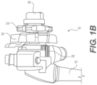
- FIG. 1B shows a proximal end of handle 12.
- Duodenoscope 10 may also include an umbilicus 16 for purposes of connecting duodenoscope 10 to sources of, for example, air, water, suction, power, etc., as well as to image processing and/or viewing equipment.
- duodenoscope may be used herein, it will be appreciated that other devices, including, but not limited to, endoscopes, colonoscopes, ureteroscopes, bronchoscopes, laparoscopes, sheaths, catheters, or any other suitable delivery device or medical device that may include an elevator or another actuatable distal tip component, may be used in connection with the devices and manufacturing methods of this disclosure.
- endoscopes colonoscopes
- ureteroscopes ureteroscopes
- bronchoscopes laparoscopes
- sheaths catheters
- any other suitable delivery device or medical device that may include an elevator or another actuatable distal tip component
- front-facing endoscopes e.g., endoscopes where a viewing element faces longitudinally forward
- any other device where a user may desire the ability to lock or unlock a portion of the device.
- Insertion portion 14 may include a sheath or shaft 18 and a distal tip 20.
- Distal tip 20 may include an imaging device 22 (e.g., a camera) and a lighting source 24 (e.g., an LED or an optical fiber).
- Imaging device 22 and lighting source 24 may face radially outward, perpendicularly, approximately perpendicularly, or otherwise transverse to a longitudinal axis of shaft 18 and distal tip 20.
- Distal tip 20 may also include an elevator 26 for changing an orientation of a tool inserted in a working channel of duodenoscope 10.
- Elevator 26 may alternatively be referred to as a swing stand, pivot stand, raising base, or any suitable other term. Elevator 26 may be pivotable via, e.g., an actuation wire or another control element that extends from handle 12, through shaft 14, to elevator 26.
- a distal portion of shaft 18 that is connected to distal tip 20 may have a steerable section 28.
- Steerable section 28 may be, for example, an articulation joint.
- Shaft 18 and steerable section 28 may include a variety of structures which are known or may become known in the art.
- Handle 12 may have one or more actuators/control mechanisms 30.
- Control mechanisms 30 may provide control over steerable section 28 or may allow for provision of air, water, suction, etc.
- handle 12 may include control knobs 32, 34 for left, right, up, and/or down control of steerable section 28.
- one of knobs 32, 34 may provide left/right control of steerable section 28, and the other of knobs 32, 34 may provide up/down control of steerable section 28.
- Handle 12 may further include one or more locking mechanisms 36 (e.g., knobs or levers) for preventing steering of steerable section 28 in at least one of an up, down, left, or right direction.
- Handle 12 may include an elevator control lever 38 (see FIG. 1B ).
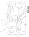
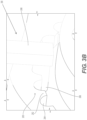
- FIGS. 2A and 2B disclose views of a handle 112, which may have any of the properties of handle 12 of FIGS. 1A-1B .
- Handle 112 may have a locking/retaining mechanism 160.
- Handle 112 may have an elevator control lever 138, having any of the properties of elevator control lever 38 of FIG. 1B .
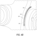
- Locking mechanism 160 includes a stationary rack gear 180 and features of elevator control lever 138 that interact with rack gear 180 in order to retain/lock elevator control lever 138 in a desired position.
- Elevator control lever 138 may include a lever body 162 and a cross bar 164.
- Cross bar 164 may be an actuator for locking/retaining and/or releasing elevator control lever 138, in a desired position.
- a radially outer surface 165 of cross bar 164 may extend radially outwardly from lever body 162.
- Radially outer surface 165 of cross bar 164 may extend radially outwardly from lever body 162 by only a small amount in order to facilitate a user contacting lever body 162 and cross bar 164 without any uncomfortable protrusions.
- Cross-bar 164 may extend laterally (e.g., substantially perpendicularly to a longitudinal axis of handle 112) through at least a portion of elevator control lever 138.
- Elevator control lever 138 may have an opening (e.g., a slit) extending at least partially therethrough for receiving cross bar 164.
- cross bar 164 may include an arm/shaft 168 that extends radially inward from radially outer surface 165.
- a feature, such as a tooth 166, may be disposed at a radially inward end of arm 168. Tooth 166 and lever body 162 may extend in substantially the same direction away from arm 168.
- a radially outward portion of cross bar 164 (having surface 165), arm 168, and tooth 166 may form a substantially C-shape. Tooth 166 may extend laterally inward (in a direction toward a center of handle 112). Tooth 166 may have a first end 172 and a second end 174. First end 172 may be flat, and second end 174 may be curved.
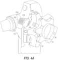
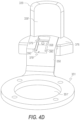
- Opening 379 may function to provide space for the working assembly and to provide linear space for distal shaft 368, protrusion 373, and shaft 367 to move. Opening 379 may be defined by alternative features, such as lever body 350 or alternative configurations of arm 378.
- Shaft 367 may be fixed to and extend radially inward from button 364 (e.g. from an end or bottom surface of button 364). Shaft 367 may extend substantially parallel relative to arm 378 and/or extend perpendicularly to the bottom surface of button 364. Shaft 367 may further comprise a flange/extension 369. Extension 369 may extend radially outwardly or perpendicularly from a center axis of shaft 367.
Landscapes
- Health & Medical Sciences (AREA)
- Life Sciences & Earth Sciences (AREA)
- Surgery (AREA)
- Engineering & Computer Science (AREA)
- Physics & Mathematics (AREA)
- Biomedical Technology (AREA)
- Medical Informatics (AREA)
- Nuclear Medicine, Radiotherapy & Molecular Imaging (AREA)
- Optics & Photonics (AREA)
- Pathology (AREA)
- Radiology & Medical Imaging (AREA)
- Veterinary Medicine (AREA)
- Public Health (AREA)
- Heart & Thoracic Surgery (AREA)
- Biophysics (AREA)
- Molecular Biology (AREA)
- Animal Behavior & Ethology (AREA)
- General Health & Medical Sciences (AREA)
- General Physics & Mathematics (AREA)
- Automation & Control Theory (AREA)
- Mechanical Engineering (AREA)
- Gastroenterology & Hepatology (AREA)
- Dental Tools And Instruments Or Auxiliary Dental Instruments (AREA)
- Infusion, Injection, And Reservoir Apparatuses (AREA)
- Manipulator (AREA)
Applications Claiming Priority (3)
| Application Number | Priority Date | Filing Date | Title |
|---|---|---|---|
| US202063132513P | 2020-12-31 | 2020-12-31 | |
| PCT/US2021/065279 WO2022146963A1 (fr) | 2020-12-31 | 2021-12-28 | Verrous d'actionneur de dispositif médical |
| EP21848418.6A EP4240219B1 (fr) | 2020-12-31 | 2021-12-28 | Verrous d'actionneur de dispositif médical |
Related Parent Applications (2)
| Application Number | Title | Priority Date | Filing Date |
|---|---|---|---|
| EP21848418.6A Division EP4240219B1 (fr) | 2020-12-31 | 2021-12-28 | Verrous d'actionneur de dispositif médical |
| EP21848418.6A Division-Into EP4240219B1 (fr) | 2020-12-31 | 2021-12-28 | Verrous d'actionneur de dispositif médical |
Publications (2)
| Publication Number | Publication Date |
|---|---|
| EP4582012A2 true EP4582012A2 (fr) | 2025-07-09 |
| EP4582012A3 EP4582012A3 (fr) | 2025-09-17 |
Family
ID=80050786
Family Applications (2)
| Application Number | Title | Priority Date | Filing Date |
|---|---|---|---|
| EP21848418.6A Active EP4240219B1 (fr) | 2020-12-31 | 2021-12-28 | Verrous d'actionneur de dispositif médical |
| EP25172452.2A Pending EP4582012A3 (fr) | 2020-12-31 | 2021-12-28 | Verrous d'actionneur de dispositif médical |
Family Applications Before (1)
| Application Number | Title | Priority Date | Filing Date |
|---|---|---|---|
| EP21848418.6A Active EP4240219B1 (fr) | 2020-12-31 | 2021-12-28 | Verrous d'actionneur de dispositif médical |
Country Status (5)
| Country | Link |
|---|---|
| US (3) | US11930997B2 (fr) |
| EP (2) | EP4240219B1 (fr) |
| CN (1) | CN116867416A (fr) |
| AU (1) | AU2021413757A1 (fr) |
| WO (1) | WO2022146963A1 (fr) |
Families Citing this family (5)
| Publication number | Priority date | Publication date | Assignee | Title |
|---|---|---|---|---|
| DE112019000935T5 (de) * | 2018-02-23 | 2020-11-26 | Fujifilm Corporation | Endoskop |
| DE102018208555A1 (de) | 2018-05-30 | 2019-12-05 | Kardion Gmbh | Vorrichtung zum Verankern eines Herzunterstützungssystems in einem Blutgefäß, Verfahren zum Betreiben und Herstellverfahren zum Herstellen einer Vorrichtung und Herzunterstützungssystem |
| DE102018211297A1 (de) | 2018-07-09 | 2020-01-09 | Kardion Gmbh | Herzunterstützungssystem und Verfahren zur Überwachung der Integrität einer Haltestruktur eines Herzunterstützungssystems |
| EP4461197A1 (fr) * | 2023-05-11 | 2024-11-13 | Ambu A/S | Endoscope avec un élément élévateur et module de commande pour l'endoscope |
| CN119157461B (zh) * | 2024-11-21 | 2025-03-25 | 湖南省华芯医疗器械有限公司 | 一种拨动组件、内窥镜手柄及内窥镜 |
Family Cites Families (11)
| Publication number | Priority date | Publication date | Assignee | Title |
|---|---|---|---|---|
| US152574A (en) * | 1874-06-30 | Improvement in brakes for vehicles | ||
| US720758A (en) * | 1902-02-28 | 1903-02-17 | Abbot Augustus Low | Hand-lever-locking device. |
| US787714A (en) * | 1904-11-12 | 1905-04-18 | Herbert Austin | Lever-and-quadrant apparatus. |
| US1186378A (en) * | 1915-10-28 | 1916-06-06 | Alfred Christensen | Locking means for control-levers. |
| US1524898A (en) * | 1924-01-11 | 1925-02-03 | John J Carey | Control lever |
| US1521308A (en) * | 1924-05-14 | 1924-12-30 | Jack E Messenger | Brake-lever spring |
| US3059498A (en) * | 1961-10-05 | 1962-10-23 | William Hunter A Boyd | Non-dead-centering mechanism |
| JP4580319B2 (ja) * | 2005-09-28 | 2010-11-10 | 株式会社東海理化電機製作所 | シフトレバー装置 |
| DE102008017300A1 (de) * | 2008-03-31 | 2009-10-01 | Karl Storz Gmbh & Co. Kg | Medizinisches Instrument mit arretierbarer Abwinkelsteuerung |
| EP2799001B1 (fr) * | 2013-05-02 | 2015-12-02 | Karl Storz GmbH & Co. KG | Instrument médical doté d'une commande de pliage pouvant être bloquée |
| US11399702B2 (en) * | 2018-12-20 | 2022-08-02 | Boston Scientific Scimed, Inc. | Ureteroscope device and method for using of such a device |
-
2021
- 2021-12-28 CN CN202180093534.1A patent/CN116867416A/zh active Pending
- 2021-12-28 EP EP21848418.6A patent/EP4240219B1/fr active Active
- 2021-12-28 WO PCT/US2021/065279 patent/WO2022146963A1/fr not_active Ceased
- 2021-12-28 EP EP25172452.2A patent/EP4582012A3/fr active Pending
- 2021-12-28 US US17/563,190 patent/US11930997B2/en active Active
- 2021-12-28 AU AU2021413757A patent/AU2021413757A1/en active Pending
-
2024
- 2024-02-14 US US18/441,200 patent/US12419494B2/en active Active
-
2025
- 2025-08-27 US US19/311,400 patent/US20260000272A1/en active Pending
Also Published As
| Publication number | Publication date |
|---|---|
| US20220202278A1 (en) | 2022-06-30 |
| CN116867416A (zh) | 2023-10-10 |
| US11930997B2 (en) | 2024-03-19 |
| US20240180398A1 (en) | 2024-06-06 |
| US20260000272A1 (en) | 2026-01-01 |
| US12419494B2 (en) | 2025-09-23 |
| AU2021413757A1 (en) | 2023-06-29 |
| WO2022146963A1 (fr) | 2022-07-07 |
| EP4240219A1 (fr) | 2023-09-13 |
| EP4582012A3 (fr) | 2025-09-17 |
| EP4240219B1 (fr) | 2025-06-04 |
Similar Documents
| Publication | Publication Date | Title |
|---|---|---|
| US12419494B2 (en) | Medical device actuator locks | |
| US12336687B2 (en) | Steering system with locking mechanism | |
| CN101513338B (zh) | 处理用内窥镜 | |
| EP4132340B1 (fr) | Mécanisme de verrouillage pour dispositifs endoscopiques | |
| EP3973894B1 (fr) | Outil d'endoscope | |
| JP2024528999A (ja) | 操作可能な医療デバイスのためのブレーキ機構および関連する方法 | |
| KR20240165462A (ko) | 세장형 관을 통한 신축성 부재를 위한 시스템 | |
| JP7217244B2 (ja) | 内視鏡器具 | |
| US20230337894A1 (en) | Actuators for medical devices and related systems and methods | |
| US20230329534A1 (en) | Medical devices and related systems and methods | |
| JP2019528097A (ja) | 操縦可能カテーテルハンドル |
Legal Events
| Date | Code | Title | Description |
|---|---|---|---|
| PUAI | Public reference made under article 153(3) epc to a published international application that has entered the european phase |
Free format text: ORIGINAL CODE: 0009012 |
|
| STAA | Information on the status of an ep patent application or granted ep patent |
Free format text: STATUS: REQUEST FOR EXAMINATION WAS MADE |
|
| 17P | Request for examination filed |
Effective date: 20250523 |
|
| AC | Divisional application: reference to earlier application |
Ref document number: 4240219 Country of ref document: EP Kind code of ref document: P |
|
| AK | Designated contracting states |
Kind code of ref document: A2 Designated state(s): AL AT BE BG CH CY CZ DE DK EE ES FI FR GB GR HR HU IE IS IT LI LT LU LV MC MK MT NL NO PL PT RO RS SE SI SK SM TR |
|
| REG | Reference to a national code |
Ref country code: DE Ref legal event code: R079 Free format text: PREVIOUS MAIN CLASS: A61B0001273000 Ipc: A61B0001000000 |
|
| PUAL | Search report despatched |
Free format text: ORIGINAL CODE: 0009013 |
|
| AK | Designated contracting states |
Kind code of ref document: A3 Designated state(s): AL AT BE BG CH CY CZ DE DK EE ES FI FR GB GR HR HU IE IS IT LI LT LU LV MC MK MT NL NO PL PT RO RS SE SI SK SM TR |
|
| RIC1 | Information provided on ipc code assigned before grant |
Ipc: A61B 1/00 20060101AFI20250808BHEP Ipc: A61B 1/005 20060101ALI20250808BHEP Ipc: A61B 1/273 20060101ALI20250808BHEP |