EP4582012A2 - Medical device actuator locks - Google Patents
Medical device actuator locks Download PDFInfo
- Publication number
- EP4582012A2 EP4582012A2 EP25172452.2A EP25172452A EP4582012A2 EP 4582012 A2 EP4582012 A2 EP 4582012A2 EP 25172452 A EP25172452 A EP 25172452A EP 4582012 A2 EP4582012 A2 EP 4582012A2
- Authority
- EP
- European Patent Office
- Prior art keywords
- handle
- bar
- cross
- actuator
- teeth
- Prior art date
- Legal status (The legal status is an assumption and is not a legal conclusion. Google has not performed a legal analysis and makes no representation as to the accuracy of the status listed.)
- Pending
Links
Images


Classifications
-
- A—HUMAN NECESSITIES
- A61—MEDICAL OR VETERINARY SCIENCE; HYGIENE
- A61B—DIAGNOSIS; SURGERY; IDENTIFICATION
- A61B1/00—Instruments for performing medical examinations of the interior of cavities or tubes of the body by visual or photographical inspection, e.g. endoscopes; Illuminating arrangements therefor
- A61B1/005—Flexible endoscopes
- A61B1/0051—Flexible endoscopes with controlled bending of insertion part
- A61B1/0052—Constructional details of control elements, e.g. handles
-
- A—HUMAN NECESSITIES
- A61—MEDICAL OR VETERINARY SCIENCE; HYGIENE
- A61B—DIAGNOSIS; SURGERY; IDENTIFICATION
- A61B1/00—Instruments for performing medical examinations of the interior of cavities or tubes of the body by visual or photographical inspection, e.g. endoscopes; Illuminating arrangements therefor
- A61B1/00064—Constructional details of the endoscope body
- A61B1/00066—Proximal part of endoscope body, e.g. handles
-
- A—HUMAN NECESSITIES
- A61—MEDICAL OR VETERINARY SCIENCE; HYGIENE
- A61B—DIAGNOSIS; SURGERY; IDENTIFICATION
- A61B1/00—Instruments for performing medical examinations of the interior of cavities or tubes of the body by visual or photographical inspection, e.g. endoscopes; Illuminating arrangements therefor
- A61B1/00002—Operational features of endoscopes
- A61B1/00039—Operational features of endoscopes provided with input arrangements for the user
- A61B1/00042—Operational features of endoscopes provided with input arrangements for the user for mechanical operation
-
- A—HUMAN NECESSITIES
- A61—MEDICAL OR VETERINARY SCIENCE; HYGIENE
- A61B—DIAGNOSIS; SURGERY; IDENTIFICATION
- A61B1/00—Instruments for performing medical examinations of the interior of cavities or tubes of the body by visual or photographical inspection, e.g. endoscopes; Illuminating arrangements therefor
- A61B1/00064—Constructional details of the endoscope body
- A61B1/00071—Insertion part of the endoscope body
- A61B1/0008—Insertion part of the endoscope body characterised by distal tip features
- A61B1/00098—Deflecting means for inserted tools
-
- A—HUMAN NECESSITIES
- A61—MEDICAL OR VETERINARY SCIENCE; HYGIENE
- A61B—DIAGNOSIS; SURGERY; IDENTIFICATION
- A61B1/00—Instruments for performing medical examinations of the interior of cavities or tubes of the body by visual or photographical inspection, e.g. endoscopes; Illuminating arrangements therefor
- A61B1/273—Instruments for performing medical examinations of the interior of cavities or tubes of the body by visual or photographical inspection, e.g. endoscopes; Illuminating arrangements therefor for the upper alimentary canal, e.g. oesophagoscopes, gastroscopes
-
- G—PHYSICS
- G05—CONTROLLING; REGULATING
- G05G—CONTROL DEVICES OR SYSTEMS INSOFAR AS CHARACTERISED BY MECHANICAL FEATURES ONLY
- G05G5/00—Means for preventing, limiting or returning the movements of parts of a control mechanism, e.g. locking controlling member
- G05G5/06—Means for preventing, limiting or returning the movements of parts of a control mechanism, e.g. locking controlling member for holding members in one or a limited number of definite positions only
-
- A—HUMAN NECESSITIES
- A61—MEDICAL OR VETERINARY SCIENCE; HYGIENE
- A61B—DIAGNOSIS; SURGERY; IDENTIFICATION
- A61B1/00—Instruments for performing medical examinations of the interior of cavities or tubes of the body by visual or photographical inspection, e.g. endoscopes; Illuminating arrangements therefor
- A61B1/273—Instruments for performing medical examinations of the interior of cavities or tubes of the body by visual or photographical inspection, e.g. endoscopes; Illuminating arrangements therefor for the upper alimentary canal, e.g. oesophagoscopes, gastroscopes
- A61B1/2736—Gastroscopes
-
- G—PHYSICS
- G05—CONTROLLING; REGULATING
- G05G—CONTROL DEVICES OR SYSTEMS INSOFAR AS CHARACTERISED BY MECHANICAL FEATURES ONLY
- G05G2505/00—Means for preventing, limiting or returning the movements of parts of a control mechanism, e.g. locking controlling member
Definitions
- Various aspects of this disclosure relate generally to devices and methods for actuators of medical devices, such as elevator levers for duodenoscopes.
- Duodenoscopes may include a handle and a sheath insertable into a body lumen of a subject.
- the sheath may terminate in a distal tip portion, which may include features such as optical elements (e.g., camera, lighting), air/water outlets, and working channel openings.
- An elevator may be disposed at a distal tip and may be actuatable in order to change an orientation of a medical device/tool passed through the working channel.
- the elevator may be pivotable or otherwise movable.
- Elements in the handle may control the elements of the distal tip.
- buttons, knobs, levers, etc. may control elements of the distal tip.
- the elevator may be controlled via a control mechanism in a handle, such as a lever, which may be attached to a control wire that attaches to the elevator.
- an actuator e.g., a lever
- the wire may move proximally and/or distally, thereby raising and/or lowering the elevator.
- a handle of a medical device may comprise an actuator; a lock movable relative to the actuator and having a feature movable relative to the actuator; and a rack having plurality of teeth separated from one another by a plurality of gaps.
- the lock may be configured to move the feature from (a) a first configuration, in which the feature is disposed in the gap, between two of the plurality of teeth, such that the two teeth inhibit the actuator from rotating; to (b) a second configuration, in which the feature is disposed outside of the gap, such that the actuator is rotatable. In the second configuration, the teeth may be disposed between the feature and the actuator.
- the feature may be biased into the first configuration.
- a spring may bias the feature into the first configuration.
- the lock may include at least one of a button or a bar.
- a shaft may extend radially inward, relative to a housing of the handle, from the at least one of the button or the bar to the feature. At least a portion of the actuator and the feature may extend away from the shaft in the same direction.
- the feature may be substantially parallel to at least a portion of the actuator.
- the shaft may extend radially through an opening in the actuator.
- the lock may include the bar.
- the bar may extend laterally through an opening in the actuator.
- the plurality of teeth may face radially inward relative to a housing of the handle.
- the plurality of the teeth may face laterally outward relative to a housing of the handle.
- the rack may be curved.
- the rack may be recessed within a surface of the handle.
- the lock may be movable in a radial direction relative to a housing of the handle.
- a shape of the teeth may complement a shape of the feature. Additionally or alternatively, the shaft of the handle may translate along a track of the actuator.
- a handle of a medical device may comprise: a rotatable actuator; a lock radially movable relative to the actuator and configured to radially move a feature relative to the actuator; and a rack having plurality of teeth separated from one another by a plurality of gaps.
- the lock may be configured to move the feature radially inward toward a handle housing from (a) a first configuration, in which the feature is disposed in a gap of the plurality of gaps, between two of the plurality of teeth, such that the two teeth inhibit the lever from rotating, to (b) a second configuration, in which the feature is disposed radially inward of the teeth, such that the actuator is rotatable.
- the feature may be biased into the first configuration.
- a method of operating a medical device may comprise: with an actuator in a first position, depressing a lock radially inward relative to the actuator, thereby moving a feature radially inward of teeth of a stationary rack gear; while depressing the lock, rotating the actuator to a second position; and with the actuator in the second position, releasing the lock, thereby moving the feature so that the teeth inhibit movement of the feature in a direction of movement of the actuator.
- the method may further comprise: with the actuator in the second position, depressing the lock radially inward relative to the actuator, thereby moving the feature radially inward of the teeth of the stationary rack gear; while depressing the lock, rotating the actuator to a third position; and with the actuator in the third position, releasing the lock, thereby moving the feature so that the teeth inhibit movement of the feature in a direction of movement of the actuator.
- the lock may include a bar or a button.
- the terms “comprises,” “comprising,” or any other variation thereof, are intended to cover a non-exclusive inclusion, such that a process, method, article, or apparatus that comprises a list of elements does not include only those elements, but may include other elements not expressly listed or inherent to such process, method, article, or apparatus.
- the term “diameter” may refer to a width where an element is not circular.
- the term “distal” refers to a direction away from an operator, and the term “proximal” refers to a direction toward an operator.
- the term “exemplary” is used in the sense of "example,” rather than “ideal.”
- the term “approximately,” or like terms includes values +/- 10% of a stated value.
- actuators or controllers of medical devices for example, levers
- Such locks may free an operator to make use of a finger that would otherwise be used to retain the lever in position.
- the lever may require a high amount of force from an operator to retain the lever in place without a locking/retaining mechanism. Locking/retaining mechanisms may help to avoid fatigue by the user.
- the examples disclosed herein use fixed gear structures to lock/retain an actuator (e.g., a lever) in a desired position.
- elevator levers are described herein, it will be appreciated that the disclosed levers may also be used for other types of controls (e.g., steering of a distal tip of the duodenoscope).
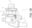
- FIG. 1A depicts an exemplary duodenoscope 10 having a handle 12 and an insertion portion 14.
- FIG. 1B shows a proximal end of handle 12.
- Duodenoscope 10 may also include an umbilicus 16 for purposes of connecting duodenoscope 10 to sources of, for example, air, water, suction, power, etc., as well as to image processing and/or viewing equipment.
- duodenoscope may be used herein, it will be appreciated that other devices, including, but not limited to, endoscopes, colonoscopes, ureteroscopes, bronchoscopes, laparoscopes, sheaths, catheters, or any other suitable delivery device or medical device that may include an elevator or another actuatable distal tip component, may be used in connection with the devices and manufacturing methods of this disclosure.
- endoscopes colonoscopes
- ureteroscopes ureteroscopes
- bronchoscopes laparoscopes
- sheaths catheters
- any other suitable delivery device or medical device that may include an elevator or another actuatable distal tip component
- front-facing endoscopes e.g., endoscopes where a viewing element faces longitudinally forward
- any other device where a user may desire the ability to lock or unlock a portion of the device.
- Insertion portion 14 may include a sheath or shaft 18 and a distal tip 20.
- Distal tip 20 may include an imaging device 22 (e.g., a camera) and a lighting source 24 (e.g., an LED or an optical fiber).
- Imaging device 22 and lighting source 24 may face radially outward, perpendicularly, approximately perpendicularly, or otherwise transverse to a longitudinal axis of shaft 18 and distal tip 20.
- Distal tip 20 may also include an elevator 26 for changing an orientation of a tool inserted in a working channel of duodenoscope 10.
- Elevator 26 may alternatively be referred to as a swing stand, pivot stand, raising base, or any suitable other term. Elevator 26 may be pivotable via, e.g., an actuation wire or another control element that extends from handle 12, through shaft 14, to elevator 26.
- a distal portion of shaft 18 that is connected to distal tip 20 may have a steerable section 28.
- Steerable section 28 may be, for example, an articulation joint.
- Shaft 18 and steerable section 28 may include a variety of structures which are known or may become known in the art.
- Handle 12 may have one or more actuators/control mechanisms 30.
- Control mechanisms 30 may provide control over steerable section 28 or may allow for provision of air, water, suction, etc.
- handle 12 may include control knobs 32, 34 for left, right, up, and/or down control of steerable section 28.
- one of knobs 32, 34 may provide left/right control of steerable section 28, and the other of knobs 32, 34 may provide up/down control of steerable section 28.
- Handle 12 may further include one or more locking mechanisms 36 (e.g., knobs or levers) for preventing steering of steerable section 28 in at least one of an up, down, left, or right direction.
- Handle 12 may include an elevator control lever 38 (see FIG. 1B ).
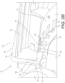
- FIGS. 2A and 2B disclose views of a handle 112, which may have any of the properties of handle 12 of FIGS. 1A-1B .
- Handle 112 may have a locking/retaining mechanism 160.
- Handle 112 may have an elevator control lever 138, having any of the properties of elevator control lever 38 of FIG. 1B .
- Locking mechanism 160 includes a stationary rack gear 180 and features of elevator control lever 138 that interact with rack gear 180 in order to retain/lock elevator control lever 138 in a desired position.
- Elevator control lever 138 may include a lever body 162 and a cross bar 164.
- Cross bar 164 may be an actuator for locking/retaining and/or releasing elevator control lever 138, in a desired position.
- a radially outer surface 165 of cross bar 164 may extend radially outwardly from lever body 162.
- Radially outer surface 165 of cross bar 164 may extend radially outwardly from lever body 162 by only a small amount in order to facilitate a user contacting lever body 162 and cross bar 164 without any uncomfortable protrusions.
- Cross-bar 164 may extend laterally (e.g., substantially perpendicularly to a longitudinal axis of handle 112) through at least a portion of elevator control lever 138.
- Elevator control lever 138 may have an opening (e.g., a slit) extending at least partially therethrough for receiving cross bar 164.
- cross bar 164 may include an arm/shaft 168 that extends radially inward from radially outer surface 165.
- a feature, such as a tooth 166, may be disposed at a radially inward end of arm 168. Tooth 166 and lever body 162 may extend in substantially the same direction away from arm 168.
- a radially outward portion of cross bar 164 (having surface 165), arm 168, and tooth 166 may form a substantially C-shape. Tooth 166 may extend laterally inward (in a direction toward a center of handle 112). Tooth 166 may have a first end 172 and a second end 174. First end 172 may be flat, and second end 174 may be curved.
- Opening 379 may function to provide space for the working assembly and to provide linear space for distal shaft 368, protrusion 373, and shaft 367 to move. Opening 379 may be defined by alternative features, such as lever body 350 or alternative configurations of arm 378.
- Shaft 367 may be fixed to and extend radially inward from button 364 (e.g. from an end or bottom surface of button 364). Shaft 367 may extend substantially parallel relative to arm 378 and/or extend perpendicularly to the bottom surface of button 364. Shaft 367 may further comprise a flange/extension 369. Extension 369 may extend radially outwardly or perpendicularly from a center axis of shaft 367.
Landscapes
- Health & Medical Sciences (AREA)
- Life Sciences & Earth Sciences (AREA)
- Surgery (AREA)
- Engineering & Computer Science (AREA)
- Physics & Mathematics (AREA)
- Biomedical Technology (AREA)
- Medical Informatics (AREA)
- Nuclear Medicine, Radiotherapy & Molecular Imaging (AREA)
- Optics & Photonics (AREA)
- Pathology (AREA)
- Radiology & Medical Imaging (AREA)
- Veterinary Medicine (AREA)
- Public Health (AREA)
- Heart & Thoracic Surgery (AREA)
- Biophysics (AREA)
- Molecular Biology (AREA)
- Animal Behavior & Ethology (AREA)
- General Health & Medical Sciences (AREA)
- General Physics & Mathematics (AREA)
- Automation & Control Theory (AREA)
- Mechanical Engineering (AREA)
- Gastroenterology & Hepatology (AREA)
- Dental Tools And Instruments Or Auxiliary Dental Instruments (AREA)
- Infusion, Injection, And Reservoir Apparatuses (AREA)
- Manipulator (AREA)
Abstract
Description
- Various aspects of this disclosure relate generally to devices and methods for actuators of medical devices, such as elevator levers for duodenoscopes.
- Duodenoscopes may include a handle and a sheath insertable into a body lumen of a subject. The sheath may terminate in a distal tip portion, which may include features such as optical elements (e.g., camera, lighting), air/water outlets, and working channel openings. An elevator may be disposed at a distal tip and may be actuatable in order to change an orientation of a medical device/tool passed through the working channel. For example, the elevator may be pivotable or otherwise movable.
- Elements in the handle may control the elements of the distal tip. For example, buttons, knobs, levers, etc. may control elements of the distal tip. The elevator may be controlled via a control mechanism in a handle, such as a lever, which may be attached to a control wire that attaches to the elevator. When an actuator (e.g., a lever) is actuated, the wire may move proximally and/or distally, thereby raising and/or lowering the elevator.
- Each of the aspects disclosed herein may include one or more of the features described in connection with any of the other disclosed aspects.
- In one example, a handle of a medical device may comprise an actuator; a lock movable relative to the actuator and having a feature movable relative to the actuator; and a rack having plurality of teeth separated from one another by a plurality of gaps. The lock may be configured to move the feature from (a) a first configuration, in which the feature is disposed in the gap, between two of the plurality of teeth, such that the two teeth inhibit the actuator from rotating; to (b) a second configuration, in which the feature is disposed outside of the gap, such that the actuator is rotatable. In the second configuration, the teeth may be disposed between the feature and the actuator.
- Any of the handles disclosed herein may have any of the following features. The feature may be biased into the first configuration. A spring may bias the feature into the first configuration. The lock may include at least one of a button or a bar. A shaft may extend radially inward, relative to a housing of the handle, from the at least one of the button or the bar to the feature. At least a portion of the actuator and the feature may extend away from the shaft in the same direction. The feature may be substantially parallel to at least a portion of the actuator. The shaft may extend radially through an opening in the actuator. The lock may include the bar. The bar may extend laterally through an opening in the actuator. The plurality of teeth may face radially inward relative to a housing of the handle. The plurality of the teeth may face laterally outward relative to a housing of the handle. The rack may be curved. The rack may be recessed within a surface of the handle. The lock may be movable in a radial direction relative to a housing of the handle. A shape of the teeth may complement a shape of the feature. Additionally or alternatively, the shaft of the handle may translate along a track of the actuator.
- In another example, a handle of a medical device may comprise: a rotatable actuator; a lock radially movable relative to the actuator and configured to radially move a feature relative to the actuator; and a rack having plurality of teeth separated from one another by a plurality of gaps. The lock may be configured to move the feature radially inward toward a handle housing from (a) a first configuration, in which the feature is disposed in a gap of the plurality of gaps, between two of the plurality of teeth, such that the two teeth inhibit the lever from rotating, to (b) a second configuration, in which the feature is disposed radially inward of the teeth, such that the actuator is rotatable.
- Any of the handles described herein may have the following features. The feature may be biased into the first configuration.
- In another example, a method of operating a medical device may comprise: with an actuator in a first position, depressing a lock radially inward relative to the actuator, thereby moving a feature radially inward of teeth of a stationary rack gear; while depressing the lock, rotating the actuator to a second position; and with the actuator in the second position, releasing the lock, thereby moving the feature so that the teeth inhibit movement of the feature in a direction of movement of the actuator.
- Any of the methods or devices disclosed herein may have any of the following features. The method may further comprise: with the actuator in the second position, depressing the lock radially inward relative to the actuator, thereby moving the feature radially inward of the teeth of the stationary rack gear; while depressing the lock, rotating the actuator to a third position; and with the actuator in the third position, releasing the lock, thereby moving the feature so that the teeth inhibit movement of the feature in a direction of movement of the actuator. The lock may include a bar or a button.
- It may be understood that both the foregoing general description and the following detailed description are exemplary and explanatory only and are not restrictive of the invention, as claimed. As used herein, the terms "comprises," "comprising," or any other variation thereof, are intended to cover a non-exclusive inclusion, such that a process, method, article, or apparatus that comprises a list of elements does not include only those elements, but may include other elements not expressly listed or inherent to such process, method, article, or apparatus. The term "diameter" may refer to a width where an element is not circular. The term "distal" refers to a direction away from an operator, and the term "proximal" refers to a direction toward an operator. The term "exemplary" is used in the sense of "example," rather than "ideal." The term "approximately," or like terms (e.g., "substantially"), includes values +/- 10% of a stated value.
- The accompanying drawings, which are incorporated in and constitute a part of this specification, illustrate aspects this disclosure and together with the description, serve to explain the principles of the disclosure.
-
FIGS. 1A and1B depict aspects of an exemplary duodenoscope. -
FIGS. 2A and2B depict a first lever for use with the duodenoscope ofFIGS. 1A-1B . -
FIGS. 3A and3B depict a second lever for use with the duodenoscope ofFIGS. 1A-1B . -
FIGS. 4A ,4B ,4C , and4D depict a third lever for use with the duodenoscope ofFIGS. 1A-1B . - It may be desirable to lock actuators or controllers of medical devices (for example, levers) of duodenoscopes in a desired position. For example, it may be desirable to retain a lever that controls an elevator in a desired position. Such locks may free an operator to make use of a finger that would otherwise be used to retain the lever in position. Furthermore, the lever may require a high amount of force from an operator to retain the lever in place without a locking/retaining mechanism. Locking/retaining mechanisms may help to avoid fatigue by the user. The examples disclosed herein use fixed gear structures to lock/retain an actuator (e.g., a lever) in a desired position. Although elevator levers are described herein, it will be appreciated that the disclosed levers may also be used for other types of controls (e.g., steering of a distal tip of the duodenoscope).
-
FIG. 1A depicts anexemplary duodenoscope 10 having a handle 12 and an insertion portion 14.FIG. 1B shows a proximal end of handle 12.Duodenoscope 10 may also include an umbilicus 16 for purposes of connectingduodenoscope 10 to sources of, for example, air, water, suction, power, etc., as well as to image processing and/or viewing equipment. Although the term duodenoscope may be used herein, it will be appreciated that other devices, including, but not limited to, endoscopes, colonoscopes, ureteroscopes, bronchoscopes, laparoscopes, sheaths, catheters, or any other suitable delivery device or medical device that may include an elevator or another actuatable distal tip component, may be used in connection with the devices and manufacturing methods of this disclosure. Although side-facing devices are particularly discussed, the embodiments described herein may also be used with front-facing endoscopes (e.g., endoscopes where a viewing element faces longitudinally forward) or any other device where a user may desire the ability to lock or unlock a portion of the device. - Insertion portion 14 may include a sheath or
shaft 18 and adistal tip 20.Distal tip 20 may include an imaging device 22 (e.g., a camera) and a lighting source 24 (e.g., an LED or an optical fiber).Distal tip 20 may be side-facing. That is,imaging device 22 and lighting source 24 may face radially outward, perpendicularly, approximately perpendicularly, or otherwise transverse to a longitudinal axis ofshaft 18 anddistal tip 20. -
Distal tip 20 may also include anelevator 26 for changing an orientation of a tool inserted in a working channel ofduodenoscope 10.Elevator 26 may alternatively be referred to as a swing stand, pivot stand, raising base, or any suitable other term.Elevator 26 may be pivotable via, e.g., an actuation wire or another control element that extends from handle 12, through shaft 14, toelevator 26. - A distal portion of
shaft 18 that is connected todistal tip 20 may have asteerable section 28.Steerable section 28 may be, for example, an articulation joint.Shaft 18 andsteerable section 28 may include a variety of structures which are known or may become known in the art. - Handle 12 may have one or more actuators/
control mechanisms 30.Control mechanisms 30 may provide control oversteerable section 28 or may allow for provision of air, water, suction, etc. For example, handle 12 may includecontrol knobs steerable section 28. For example, one ofknobs steerable section 28, and the other ofknobs steerable section 28. Handle 12 may further include one or more locking mechanisms 36 (e.g., knobs or levers) for preventing steering ofsteerable section 28 in at least one of an up, down, left, or right direction. Handle 12 may include an elevator control lever 38 (seeFIG. 1B ). Elevator control lever 38 may raise and/orlower elevator 26, via connection between lever 38 and an actuating wire that extends from lever 38, throughshaft 18, toelevator 26. A port 40 may allow passage of a tool through port 40, into a working channel of theduodenoscope 10, throughsheath 18, todistal tip 20. - In use, an operator may insert at least a portion of
shaft 18 into a body lumen of a subject.Distal tip 20 may be navigated to a procedure site in the body lumen. The operator may insert a tool (not shown) into port 40, and pass the tool throughshaft 18 via a working channel todistal tip 20. The tool may exit the working channel atdistal tip 20. The user may use elevator control lever 38 to raiseelevator 26 and angle the tool toward a desired location (e.g., a papilla of the pancreaticobiliary tract). The user may use the tool to perform a medical procedure. -
FIGS. 2A and2B disclose views of ahandle 112, which may have any of the properties of handle 12 ofFIGS. 1A-1B . Handle 112 may have a locking/retaining mechanism 160. Handle 112 may have anelevator control lever 138, having any of the properties of elevator control lever 38 ofFIG. 1B .Locking mechanism 160 includes astationary rack gear 180 and features ofelevator control lever 138 that interact withrack gear 180 in order to retain/lockelevator control lever 138 in a desired position. -
Elevator control lever 138 may include alever body 162 and across bar 164.Cross bar 164 may be an actuator for locking/retaining and/or releasingelevator control lever 138, in a desired position. A radiallyouter surface 165 ofcross bar 164 may extend radially outwardly fromlever body 162. Radiallyouter surface 165 ofcross bar 164 may extend radially outwardly fromlever body 162 by only a small amount in order to facilitate a user contactinglever body 162 andcross bar 164 without any uncomfortable protrusions.Cross-bar 164 may extend laterally (e.g., substantially perpendicularly to a longitudinal axis of handle 112) through at least a portion ofelevator control lever 138.Elevator control lever 138 may have an opening (e.g., a slit) extending at least partially therethrough for receivingcross bar 164. - As shown in
FIG. 2B ,cross bar 164 may include an arm/shaft 168 that extends radially inward from radiallyouter surface 165. A feature, such as a tooth 166, may be disposed at a radially inward end ofarm 168. Tooth 166 andlever body 162 may extend in substantially the same direction away fromarm 168. A radially outward portion of cross bar 164 (having surface 165),arm 168, and tooth 166 may form a substantially C-shape. Tooth 166 may extend laterally inward (in a direction toward a center of handle 112). Tooth 166 may have afirst end 172 and asecond end 174.First end 172 may be flat, andsecond end 174 may be curved. Alternative shapes may be used forfirst end 172 andsecond end 174 within the scope of the disclosure. A radiallyouter surface 165 of cross bar 164 (and other portions of cross bar 164) may extend further in the lateral direction than tooth 166 does, in order to facilitate tooth 166 engaging withstationary rack 180, as discussed in further detail below. Cross-bar 164 (includingarm 168 and tooth 166) may be substantially flat (i.e., side surfaces of cross-bar 164 may be planar). -
Elevator control lever 138 andcross bar 164 may include any suitable material. For example,elevator control lever 138 and/or crossbar 164 may include polymers (e.g., plastic), composites, or metal. In one example,elevator control lever 138 may be formed from plastic, and crossbar 164 may be formed from metal.Elevator control lever 138 may be formed of a single, unitary material or a plurality of components secured to one another.Cross-bar 164 may be formed of a single, unitary material or a plurality of components secured to one another. -
Stationary rack gear 180 may include a plurality ofteeth 182, separated from one another bygaps 184.Rack gear 180 may have a curved shape, to match an arcuate path traveled byelevator control lever 138 whenlever 138 is actuated.Teeth 182 may extend in a laterally outward direction (away from a center of handle 112). As shown inFIG. 2B , eachtooth 182 may have a ledge 186 that extends further in a lateral direction than a remainder oftooth 184. Abody 188 oftooth 182 may be recessed from ledge 186 and may have a rounded/arcuate radially inner surface. A shape ofteeth 182 andgaps 184 may complement a shape of tooth 166. For example, rounded/arcuate radially inner surface ofbody 188 may complement a rounded shape of tooth 166. -
Stationary rack gear 180 may be formed integrally with a housing ofhandle 112. Alternatively,stationary rack gear 180 may be a separate piece that is fixedly attached to a housing ofhandle 112.Stationary rack gear 180 may be one single piece or may be formed from a plurality of pieces.Stationary rack gear 180 may be formed from any suitable material or combination of materials (including, e.g., polymer, such as plastic, composite, or metal). - In operation, a user may make contact with
lever body 162 ofelevator control lever 138 in order to raise or lower the elevator. In doing so, the user may depresscross bar 164 in a radially inward direction, by exerting a radially inward force on radiallyoutward surface 165 ofcross bar 164.Cross-bar 164 may be rigid such that tooth 166 moves radially inward. Ascross bar 164 is depressed, a radially outward surface of tooth 166 ofcross bar 164 may move radially inward of ledge 186, such that tooth 166 does not interfere withteeth 182 ofgear rack 180. Thus, whencross bar 164 is depressed, the user may moveelevator control lever 138 to raise or lower the elevator. -
Cross-bar 164 may be biased in a radially outward direction to the configuration ofFIG. 2B . For example,cross bar 164 may have shape memory properties, or a spring may exert a radially outward force oncross bar 164. Alternatively,cross bar 164 may attach to lever 138 via a living hinge or other biased hinge, so that a normal (i.e., relaxed) position ofcross bar 164 is as shown inFIG. 2B .Cross-bar 164 therefore moves relative tolever 138. Therefore, when the user releases contact fromsurface 165 ofcross bar 164,cross bar 164 may move radially outward to the configuration ofFIG. 2B . In the configuration ofFIG. 2B , tooth 166 may be positioned withingap 184 such that tooth 166 interferes withteeth 182 of stationary gear rack 180 (e.g., tooth 166 may be between two adjacent 186) along a direction of movement oflever 138. In the configuration ofFIG. 2B , a position of tooth 166 ofcross bar 164 may preventelevator control lever 138 from being moved to raise or lower the elevator. Interaction betweencross bar 164 andstationary rack gear 180 may thus retainelevator control lever 138 in a desired position (e.g., locking elevator control lever 138). - Because
stationary rack gear 180 may have a plurality ofteeth 182 andgaps 184,locking mechanism 160 may serve to retainelevator control lever 138 within a plurality of positions, and therefore retainelevator 26 in any of a number of positions. A user may choose a position at which to lockelevator control 138. The user may also depresscross bar 164 to moveelevator control lever 138 and then releasecross bar 164 to retain/lockelevator control lever 138 in a new position. -
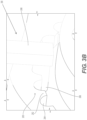
FIGS. 3A and3B depict analternative handle 212, which may have any of the properties ofhandles 12 or 112, except as specified below. Some of the structures ofFIG. 3A are transparent onFIG. 3B , in order to show details of particular aspects. Where feasible, parallel reference numbers are used to denote like structures betweenhandles elevator control lever 238 that interacts with astationary rack gear 280. -
Elevator control lever 238 may have a lever body 250 (shown inFIG. 3A but omitted fromFIG. 3B for clarity). Lever body 250 may have an angled shape that conforms to a surface ofhandle 212. As shown inFIG. 3A , lever body 250 may have twosegments 252, 256 that extend along a substantially radial direction. Betweensegments 252 and 256 is a segment 254 that extends substantially laterally, perpendicular tosegments 252 and 256. A radially outer end of segment 256 may be joined to asegment 258 that extends substantially parallel to segment 254. Segment 254 may form an end of lever body 250. Lever body 250 may be one single piece or may be formed from a plurality of pieces. Lever body 250 may be formed from any suitable material or combination of materials (including, e.g., polymer, such as plastic, composite, or metal). - A button 264 may extend approximately parallel to
segment 258 and may be disposed radially outward ofsegment 258. Button 264 may be an actuator for locking/retaininglever 238 in a desired position and/or releasing/unlockinglever 238. Aspring 276 may extend betweensegment 258 of lever body 250 and button 264. Button 264 may be movable in a substantially radial direction, approximately parallel tosegments 252 and 256.Spring 276 may bias button 264 in a substantially radially outward direction (which, as discussed below, may be a locked configuration). Other, alternative means may also be used to bias button 264 radially outward, into a configuration in which button 264 is not depressed. For example, button 264 may have shape memory properties. - A shaft 268 may be fixed to and extend radially inward from button 264 (e.g., from an end of button 264). Shaft 268 may extend substantially parallel to
segments 252 and 256. Segment 256 may be disposed between shaft 268 and a housing ofhandle 212. Shaft 268 may extend radially inward through an opening in segment 254 and may be movable relative to lever body 250, along withbutton 238.Button 238 and shaft 268 may be one single piece or may be formed from a plurality of pieces.Button 238 and shaft 268 may be formed from any suitable material or combination of materials (including, e.g., polymer, such as plastic, composite, or metal). -
Housing 278 may enclose one or more of segment 256,segment 258,spring 276, and/or portions of shaft 268 that are radially outward of segment 254. Button 264 and shaft 268 may be movable relative tohousing 278. - As shown in
FIG. 3B , a feature, such as a peg 266, may extend laterally inward from shaft 268, substantially parallel tosegments 254 and 258. Peg 266 may extend in a direction toward an interior of handle 212 (toward segment 256). Peg 266, segment 254, and button 264 may extend away from shaft 268 in substantially the same direction. Peg 266, shaft 268, and button 264 may form approximately a C-shape. Peg 266 may have, for example, a rounded shape or any other suitable shape. Peg 266 and shaft 268 may be one single piece or may be formed from a plurality of pieces. Peg 266 and shaft 268 may be formed from any suitable material or combination of materials (including, e.g., polymer, such as plastic, composite, or metal). -
Stationary rack gear 280 may be formed on a surface of a housing ofhandle 212 that faces radially inward. For example,stationary rack gear 280 may be a cut-out formed in a housing ofhandle 212. A plurality ofteeth 282 and a plurality ofgaps 284 betweenteeth 282 may be formed on the radially-inward facing surface of the housing ofhandle 212.Teeth 282 may face/extend radially inward. Becausestationary rack gear 280 is formed on a cutout,teeth 282 may not interfere with a finger/hand of a user (which may cause an operator's glove to rip, for example).Stationary rack gear 280 may have a curved shape to correspond to a path of motion oflever 238. -
Gaps 284 may have a curved (e.g., substantially semicircular) cross-sectional shape. Alternatively,gaps 284 may have another shape. A shape ofgaps 284 may complement a shape of peg 266. -
Stationary rack 280 may be integrally formed with a housing ofhandle 212 or may be a separate piece from the housing ofhandle 212.Stationary rack 280 may be one single piece or may be formed from a plurality of pieces.Stationary rack 280 may be formed from any suitable material or combination of materials (including, e.g., polymer, such as plastic, composite, or metal). - In operation, a user may depress button 264, which may move shaft 268 in a substantially radially inward direction, thereby moving peg 266 in a substantially radially inward direction. Peg 266, when moved in a substantially radially inward direction, may clear
teeth 282 ofstationary gear rack 280, such thatteeth 282 do not interfere with peg 266. In other words, an entirety of peg 266 may be disposed radially inward ofteeth 282. Thus, when button 264 is depressed, elevator control lever 238 (including lever body 250) may be moved to adjust a positioning of the elevator. - When the user releases button 264,
spring 276 may exert a force on button 264 in a substantially radially outward direction (i.e., button 264 may be biased to the undepressed configuration). As button 264 moves radially outward, shaft 268 and peg 266 also move radially outward. When button 264 is not depressed, peg 266 may be disposed within agap 284 ofstationary rack gear 280. At least a portion of peg 266 may be disposed radially inward of a radially outward edge of surroundingteeth 282.Teeth 282 may interfere with peg 266 along a direction of movement oflever 238.Teeth 282 may thus limit movement of peg 266 and, thus,elevator control lever 238. - Because
stationary rack gear 280 may have a plurality ofteeth 282 andgaps 284, locking mechanism 260 may serve to retainelevator control lever 238 at a plurality of positions, and therebysecure elevator 26 at any of a plurality of positions. A user may choose a position at which to lockelevator control 238. The user may also depress button 264 to moveelevator control lever 238 and then release button 264 to retain/lockelevator control lever 238 in a new position. -
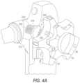
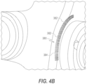
FIGS. 4A-4D depict analternative handle 312, which may have any of the properties ofhandles handles FIGS. 3A and3B , handle 312 may include alocking mechanism 360.Locking mechanism 360 may include anelevator control lever 338 that interacts with astationary rack gear 380, shown inFIGs. 4B and4C and to be described further herein. -
Elevator control lever 338 may include abutton 364 positioned radially outward from adjacent portions ofhandle 312, toward a user.Button 364 may be an actuator for locking/retainingelevator control lever 338 in a desired position and/or releasing/unlockinglever 338. An outermost surface ofbutton 364 may include a smooth surface, a rough surface (i.e. textured), or otherwise be padded to provide comfort to the user and/or to facilitate a more secure grip. Theelevator control lever 338, including itsbutton 364, like any other structure oflocking mechanism 360, may be comprised of a variety of materials, such as composites, stainless steel, plastics, polymers, or any alternative or combination of materials commonly used in the art. For example,button 364 may be comprised of a composite material, and a remainder ofcontrol lever 338 may be comprised of a stainless steel or plastic. -
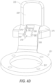
Button 364 is surrounded by, and translates within, ahousing 339.Housing 339 is ring-like and defines an internal aperture 339' that receives and housesbutton 364.FIG. 4D showshousing 339 and aperture 339', withoutbutton 364.iButton 364, when pressed, will translate relative tohousing 339 towards surfaces ofhandle 312. -
Housing 339 is integral with, or otherwise connected to, and fixed to an arm 378 (shown in more detail inFIGS. 4C and4D ).Arm 378 has a semi-circular cross-sectional shape (seeFIG. 4A ) and provides support to controllever 338 and raisescontrol lever 338 away from outer surfaces ofhandle 312, to limit undesired interactions during use between thecontrol lever 338 and thehandle 312 or other components ofdevice 10 ofFIG. 1 .Arm 378 is integral with, or otherwise connected to, and fixed to alever body 350. Alternatively,arm 378 may be a separate component coupled tolever body 350 by means of glue, fasteners, a press-fit, or any other means commonly known in the art.Lever body 350 may have a shape that conforms to, complements, or otherwise wraps around, a surface ofhandle 312. -
Lever body 350 is integral with, or otherwise connected to, and fixed to aring 351 that movably couples controllever 338 to the remainder ofhandle 312.Ring 351 encloses and defines an inner aperture 351' that receives structure for connectingknobs Ring 351 mounts to the handle housing in a manner that permits rotation ofring 351 about its central axis, as lockinglever 338 is rotated/pivoted by a user. -
FIG. 4B shows an outer surface ofhandle 312.Stationary rack 380 may be integrated into or otherwise formed withhandle 312.Stationary rack 380 may comprise a plurality ofteeth 382 separated by a plurality ofgaps 384.Stationary rack 380 may be curved along thehandle 312 so as to engage with theelevator control lever 338 along the entire length of the path of motion oflever 338.Stationary rack 380 may have a radius of curvature that is the same as or approximately the same as the radius of curvature of the path of motion oflever 338. The plurality ofteeth 382 and the plurality ofgaps 384 may be one size or a variety of sizes so as to engage withlever 338. Each of the plurality ofteeth 382 may extend perpendicularly away from the outer surface ofhandle 312.Stationary rack 380 may be an integral component ofhandle 312 or a separate component fixedly coupled to handle 312 by means of glue, a press-fit, ultrasonic welding, fasteners, or any other means commonly known in the art. In such a configuration,stationary rack 380 may be comprised of the same material ashandle 312 or a different material. For example, handle 312 may be comprised of a polycarbonate material, andstationary rack 380 may be comprised of a stainless steel. -
FIG. 4C shows a cross-section oflocking mechanism 360 to demonstrate the interaction between internal components ofcontrol lever 338 andstationary rack 380. Aprotrusion 371 ofbutton 364 travels within arecess 370 ofhousing 339 and prevents thebutton 364 from travelling too far, acting as a stop to limit radially inward movement ofbutton 364. For example, in a pressed configuration ofbutton 364,protrusion 371 travels downward withinrecess 370 ofhousing 339.Button 364 is stopped (i.e. can no longer be pressed) when a bottom face ofprotrusion 371 abuts a bottom face within therecess 370. Similarly,button 364 is prevented from continuous upward travel once a top face ofprotrusion 371 abuts a top face ofrecess 370, or, as described below, adistal shaft 368 abutssegment 358, as described below. The length and depth ofrecess 370 may vary according to the desired amount of travel forbutton 364. On the opposite side ofbutton 364, aprotrusion 373 ofbutton 364 travels within anopening 379 ofarm 378 andlever body 350. A top face ofprotrusion 373 may abut a bottom face of 372 of opening 379 in a first configuration, as shown inFIG. 4C . Opening 379 ofarm 378 andlever body 350 contains ashaft 367. Opening 379 may function to provide space for the working assembly and to provide linear space fordistal shaft 368,protrusion 373, andshaft 367 to move. Opening 379 may be defined by alternative features, such aslever body 350 or alternative configurations ofarm 378.Shaft 367 may be fixed to and extend radially inward from button 364 (e.g. from an end or bottom surface of button 364).Shaft 367 may extend substantially parallel relative toarm 378 and/or extend perpendicularly to the bottom surface ofbutton 364.Shaft 367 may further comprise a flange/extension 369.Extension 369 may extend radially outwardly or perpendicularly from a center axis ofshaft 367.Extension 369 may be utilized to hold or confine aspring 376 to a lower portion (as shown) or upper portion ofshaft 367. However,extension 369 may be omitted in other embodiments such that thespring 376 is not confined to a limited portion of theshaft 367.Shaft 367 may extend radially inward through an opening in a wall/segment 358 and may be movable relative to leverbody 350 andarm 378, along withbutton 364.Segment 358 may extend perpendicularly outward from asurface defining opening 379, and dividesopening 379 into a portion above segment 358 (housing spring 376) and a portion belowsegment 358.Button 364 andshaft 367 may be one single piece or may be formed from a plurality of pieces.Shaft 367 may be circular in cross-section (as shown), square, rectangular, or otherwise shaped to fit withinopening 379 and the opening insegment 358. - A distal end of
shaft 367 may include adistal shaft 368.Distal shaft 368 may be a separate component ofshaft 367 or be otherwise formed with a remainder of shaft 367 (i.e. as one component).Distal shafts 368 is confined belowsegment 358 to, along with other portions ofshaft 367 andspring 369, control the displacement ofbutton 364.Segment 358 may extend the entire width ofopening 379 to create two openings (379 and 379'), as shown inFIG. 4D . Alternatively,segment 358 may extend a partial width ofopening 379 such thatopening 379 is continuous above and belowsegment 358.Distal shaft 368 may be rectangular in cross-section, as shown, or otherwise shaped to fit within opening 379'.Distal shaft 368 may include grooves in its sides that travel along a track 390 (shown inFIG. 4D ) extending withinopening 379, 379'.Track 390 can be utilized to ensuredistal shaft 368 remains in position to prevent jamming or breakage of thelocking mechanism 360. - As shown in
FIG. 4C , a feature, such as apeg 366, may extend laterally outward fromdistal shaft 368 and toward an interior ofhandle 312.Peg 366,distal shaft 368,shaft 367, andbutton 364 may form approximately a C-shape.Peg 366 may have, for example, a rounded shape or any other suitable shape to fit betweenteeth 382 and withingaps 384 of therack gear 380.Gaps 384 andteeth 382 may be shaped similarly to the gaps and teeth of previous embodiments, described above with reference toFIGs. 2A-3B . - The embodiment of
FIGs. 4A-4D operates in a similar manner to the embodiment described inFIGs. 2A-3B . For example, in a first configuration, whenbutton 364 is released,button 364 is biased upward byspring 376. In this released state, a top surface ofshaft 368 may touch or abut a bottom surface ofsegment 358 and prevent additional lateral, or upward, movement of thebutton 364. Additionally or alternatively,protrusion 371 may touch or abut a bottom surface of opening 370 in the released state. This may occur simultaneously as the top surface ofshaft 368 touches or abuts the bottom surface ofsegment 358 or this may occur as a fail-safe, for example, ifprotrusion 358 fails during use. Additionally, in this configuration, peg 366 is positioned within agap 384 and betweenteeth 382. Accordingly, in this position, thecontrol lever 338 is locked, unmovable, and cannot pivot or rotate. - To unlock the
lever 338, a user may depressbutton 364. Whenbutton 364 is depressed, thespring 376 is depressed andshaft 367 anddistal shaft 368 are lowered withinopenings 379, 379'. In effect, peg 366 is moved in a substantially radially inward direction, clearing the bottom ofteeth 382. Withpeg 366 belowteeth 382,elevator control lever 338 is movable (i.e. in an unlocked position) and can be pivoted/rotated. In alternating between the first configuration and the second configuration, a user can achieve a desired position of the elevator or accessory tool (not shown). - While principles of this disclosure are described herein with reference to illustrative examples for particular applications, it should be understood that the disclosure is not limited thereto. Those having ordinary skill in the art and access to the teachings provided herein will recognize additional modifications, applications, and substitution of equivalents all fall within the scope of the examples described herein. Additionally, a variety of elements from each of the presented embodiments can be combined to achieve a same or similar result as one or more of the disclosed embodiments. For example, elements of
FIGs. 2A-2B may be combined with one or more elements of the embodiments depicted inFIGs. 3A-3B and/or 4A-4D. Accordingly, the invention is not to be considered as limited by the foregoing description.
The present invention also relates to the following aspects. - 1. A handle of a medical device, the handle comprising:
- an actuator;
- a lock movable relative to the actuator and having a feature movable relative to the actuator; and
- a rack having plurality of teeth separated from one another by a plurality of gaps, wherein the lock is configured to move the feature from (a) a first configuration, in which the feature is disposed in the gap, between two of the plurality of teeth, such that the two teeth inhibit the actuator from rotating; to (b) a second configuration, in which the feature is disposed outside of the gap, such that the actuator is rotatable, and wherein, in the second configuration, the teeth are disposed between the feature and the actuator.
- 2. The handle of aspect 1, wherein the feature is biased into the first configuration.
- 3. The handle of aspect 2, further comprising a spring, wherein the spring biases the feature into the first configuration.
- 4. The handle of any one of the preceding aspects, wherein the lock includes at least one of a button or a bar.
- 5. The handle of aspect 4, wherein a shaft extends radially inward, relative to a housing of the handle, from the at least one of the button or the bar to the feature.
- 6. The handle of aspect 5, wherein at least a portion of the actuator and the feature extend away from the shaft in the same direction.
- 7. The handle one of aspects 5 or 6, wherein the feature is substantially parallel to at least a portion of the actuator.
- 8. The handle of any one of aspects 4-7, wherein the shaft extends radially through an opening in the actuator.
- 9. The handle of any one of aspects 4-7, wherein the lock includes the bar, and wherein the bar extends laterally through an opening in the actuator.
- 10. The handle of any one of the preceding aspects, wherein the plurality of teeth extend radially inward relative to a housing of the handle.
- 11. The handle of any one of the preceding aspects, wherein the plurality of the teeth extend laterally outward relative to a housing of the handle.
- 12. The handle of any one of the preceding aspects, wherein the rack is curved.
- 13. The handle of any one of the preceding aspects, wherein the rack protrudes from a surface of the handle.
- 14. The handle of any one of the preceding aspects, wherein the lock is movable in a radial direction relative to a housing of the handle.
- 15. The handle of any one of the preceding aspect, wherein the shaft translates along a track of the actuator.
Claims (15)
- A handle of a medical device, the handle comprising:an actuator (138);a lock movable relative to the actuator (138) and having a feature movable relative to the actuator; anda rack (180) having a plurality of teeth (182) separated from one another by a plurality of gaps (184), wherein the lock is configured to move the feature from(a) a first configuration, in which the feature is disposed in a gap of the plurality of gaps (184), between two of the plurality of teeth (182), such that the two teeth inhibit the actuator from rotating; to(b) a second configuration, in which the feature is disposed outside of the gap, such that the actuator is rotatable, and wherein, in the second configuration, the teeth (184) are disposed between the feature and the actuator,wherein the feature is a cross-bar (164) and is configured to be depressed, and,wherein, when the cross-bar is depressed, a radially outward surface of a tooth (166) of the cross-bar (164) is configured to move radially inward of a ledge (186) of the plurality of teeth (182) of the rack (180), such that tooth (166) does not interfere with the plurality of teeth (182) of the rack (180).
- The handle of claim 1, wherein the cross-bar (164) is configured to be depressed in a radially inward direction by exerting a radially inward force on a radially outward surface (165) of cross-bar (164).
- The handle of claim 1 or 2, wherein the cross-bar (164) is biased in a radially outward direction.
- The handle of one of the previous claims, wherein the actuator (138) has an opening, in particular a slit, extending at least partially therethrough for receiving the cross-bar (164).
- The handle of one of the previous claims, wherein a radially outer surface (165) of cross-bar (164) extends further in the lateral direction than the tooth (166) of the cross-bar (164).
- The handle of one of the previous claims, wherein the cross-bar (164) has shape memory properties, or wherein a spring exerts a radially outward force on cross-bar (164).
- The handle of one of the previous claims, wherein rack (180) has a curved shape, to match an arcuate path traveled by the actuator (138) when the actuator (138) is actuated.
- The handle of one of the previous claims, wherein the plurality of teeth (182) extends in a laterally outward direction away from a center of the handle (112).
- The handle of one of the previous claims, wherein a body (188) of tooth (182) is recessed from the ledge (186) and/or has a rounded/arcuate radially inner surface.
- The handle of one of the previous claims, wherein the cross-bar (164) includes an arm or shaft (168) that extends radially inward from a radially outer surface (165) of the cross-bar (164) and wherein the tooth (166) of the cross-bar (164) is disposed at a radially inward end of arm or shaft (168).
- The handle of claim 10, wherein the tooth (166) of the cross-bar (164) and a lever body (162) of the actuator (138) extend in substantially the same direction away from the arm or shaft (168).
- The handle of claims 10 or 11, wherein a radially outward portion of the cross-bar (164), the arm (168), and the tooth (166) of the cross-bar (164) form a substantially C-shape.
- The handle of one of the previous claims, wherein the tooth (166) of the cross-bar (164) has a first end (172) and a second end (174), and wherein the first end (172) is flat, and/or the second end (174) is curved.
- The handle of one of the previous claims, wherein the actuator is an elevator control lever (138) configured to raise and/or lower an elevator (26).
- A medical device (10) including a handle according to one of the previous claims, wherein the device comprises an elevator (26) for changing an orientation of a tool inserted in a working channel of the medical device (10).
Applications Claiming Priority (3)
| Application Number | Priority Date | Filing Date | Title |
|---|---|---|---|
| US202063132513P | 2020-12-31 | 2020-12-31 | |
| PCT/US2021/065279 WO2022146963A1 (en) | 2020-12-31 | 2021-12-28 | Medical device actuator locks |
| EP21848418.6A EP4240219B1 (en) | 2020-12-31 | 2021-12-28 | Medical device actuator locks |
Related Parent Applications (2)
| Application Number | Title | Priority Date | Filing Date |
|---|---|---|---|
| EP21848418.6A Division EP4240219B1 (en) | 2020-12-31 | 2021-12-28 | Medical device actuator locks |
| EP21848418.6A Division-Into EP4240219B1 (en) | 2020-12-31 | 2021-12-28 | Medical device actuator locks |
Publications (2)
| Publication Number | Publication Date |
|---|---|
| EP4582012A2 true EP4582012A2 (en) | 2025-07-09 |
| EP4582012A3 EP4582012A3 (en) | 2025-09-17 |
Family
ID=80050786
Family Applications (2)
| Application Number | Title | Priority Date | Filing Date |
|---|---|---|---|
| EP21848418.6A Active EP4240219B1 (en) | 2020-12-31 | 2021-12-28 | Medical device actuator locks |
| EP25172452.2A Pending EP4582012A3 (en) | 2020-12-31 | 2021-12-28 | Medical device actuator locks |
Family Applications Before (1)
| Application Number | Title | Priority Date | Filing Date |
|---|---|---|---|
| EP21848418.6A Active EP4240219B1 (en) | 2020-12-31 | 2021-12-28 | Medical device actuator locks |
Country Status (5)
| Country | Link |
|---|---|
| US (3) | US11930997B2 (en) |
| EP (2) | EP4240219B1 (en) |
| CN (1) | CN116867416A (en) |
| AU (1) | AU2021413757A1 (en) |
| WO (1) | WO2022146963A1 (en) |
Families Citing this family (5)
| Publication number | Priority date | Publication date | Assignee | Title |
|---|---|---|---|---|
| DE112019000935T5 (en) * | 2018-02-23 | 2020-11-26 | Fujifilm Corporation | endoscope |
| DE102018208555A1 (en) | 2018-05-30 | 2019-12-05 | Kardion Gmbh | Apparatus for anchoring a cardiac assist system in a blood vessel, method of operation, and method of making a device and cardiac assist system |
| DE102018211297A1 (en) | 2018-07-09 | 2020-01-09 | Kardion Gmbh | Cardiac support system and method for monitoring the integrity of a support structure of a cardiac support system |
| EP4461197A1 (en) * | 2023-05-11 | 2024-11-13 | Ambu A/S | Endoscope with an elevator element and control module for the endoscope |
| CN119157461B (en) * | 2024-11-21 | 2025-03-25 | 湖南省华芯医疗器械有限公司 | A toggle assembly, endoscope handle and endoscope |
Family Cites Families (11)
| Publication number | Priority date | Publication date | Assignee | Title |
|---|---|---|---|---|
| US152574A (en) * | 1874-06-30 | Improvement in brakes for vehicles | ||
| US720758A (en) * | 1902-02-28 | 1903-02-17 | Abbot Augustus Low | Hand-lever-locking device. |
| US787714A (en) * | 1904-11-12 | 1905-04-18 | Herbert Austin | Lever-and-quadrant apparatus. |
| US1186378A (en) * | 1915-10-28 | 1916-06-06 | Alfred Christensen | Locking means for control-levers. |
| US1524898A (en) * | 1924-01-11 | 1925-02-03 | John J Carey | Control lever |
| US1521308A (en) * | 1924-05-14 | 1924-12-30 | Jack E Messenger | Brake-lever spring |
| US3059498A (en) * | 1961-10-05 | 1962-10-23 | William Hunter A Boyd | Non-dead-centering mechanism |
| JP4580319B2 (en) * | 2005-09-28 | 2010-11-10 | 株式会社東海理化電機製作所 | Shift lever device |
| DE102008017300A1 (en) * | 2008-03-31 | 2009-10-01 | Karl Storz Gmbh & Co. Kg | Medical instrument with lockable angle control |
| EP2799001B1 (en) * | 2013-05-02 | 2015-12-02 | Karl Storz GmbH & Co. KG | Medical instrument with adjustable angle control |
| US11399702B2 (en) * | 2018-12-20 | 2022-08-02 | Boston Scientific Scimed, Inc. | Ureteroscope device and method for using of such a device |
-
2021
- 2021-12-28 CN CN202180093534.1A patent/CN116867416A/en active Pending
- 2021-12-28 EP EP21848418.6A patent/EP4240219B1/en active Active
- 2021-12-28 WO PCT/US2021/065279 patent/WO2022146963A1/en not_active Ceased
- 2021-12-28 EP EP25172452.2A patent/EP4582012A3/en active Pending
- 2021-12-28 US US17/563,190 patent/US11930997B2/en active Active
- 2021-12-28 AU AU2021413757A patent/AU2021413757A1/en active Pending
-
2024
- 2024-02-14 US US18/441,200 patent/US12419494B2/en active Active
-
2025
- 2025-08-27 US US19/311,400 patent/US20260000272A1/en active Pending
Also Published As
| Publication number | Publication date |
|---|---|
| US20220202278A1 (en) | 2022-06-30 |
| CN116867416A (en) | 2023-10-10 |
| US11930997B2 (en) | 2024-03-19 |
| US20240180398A1 (en) | 2024-06-06 |
| US20260000272A1 (en) | 2026-01-01 |
| US12419494B2 (en) | 2025-09-23 |
| AU2021413757A1 (en) | 2023-06-29 |
| WO2022146963A1 (en) | 2022-07-07 |
| EP4240219A1 (en) | 2023-09-13 |
| EP4582012A3 (en) | 2025-09-17 |
| EP4240219B1 (en) | 2025-06-04 |
Similar Documents
| Publication | Publication Date | Title |
|---|---|---|
| US12419494B2 (en) | Medical device actuator locks | |
| US12336687B2 (en) | Steering system with locking mechanism | |
| CN101513338B (en) | Medical treatment endoscope | |
| EP4132340B1 (en) | Locking mechanisms for endoscopic devices | |
| EP3973894B1 (en) | Endoscope tool | |
| JP2024528999A (en) | Braking Mechanism for Manipulable Medical Devices and Related Methods - Patent application | |
| KR20240165462A (en) | System for elastic absence through elongated tube | |
| JP7217244B2 (en) | endoscopic instruments | |
| US20230337894A1 (en) | Actuators for medical devices and related systems and methods | |
| US20230329534A1 (en) | Medical devices and related systems and methods | |
| JP2019528097A (en) | Steerable catheter handle |
Legal Events
| Date | Code | Title | Description |
|---|---|---|---|
| PUAI | Public reference made under article 153(3) epc to a published international application that has entered the european phase |
Free format text: ORIGINAL CODE: 0009012 |
|
| STAA | Information on the status of an ep patent application or granted ep patent |
Free format text: STATUS: REQUEST FOR EXAMINATION WAS MADE |
|
| 17P | Request for examination filed |
Effective date: 20250523 |
|
| AC | Divisional application: reference to earlier application |
Ref document number: 4240219 Country of ref document: EP Kind code of ref document: P |
|
| AK | Designated contracting states |
Kind code of ref document: A2 Designated state(s): AL AT BE BG CH CY CZ DE DK EE ES FI FR GB GR HR HU IE IS IT LI LT LU LV MC MK MT NL NO PL PT RO RS SE SI SK SM TR |
|
| REG | Reference to a national code |
Ref country code: DE Ref legal event code: R079 Free format text: PREVIOUS MAIN CLASS: A61B0001273000 Ipc: A61B0001000000 |
|
| PUAL | Search report despatched |
Free format text: ORIGINAL CODE: 0009013 |
|
| AK | Designated contracting states |
Kind code of ref document: A3 Designated state(s): AL AT BE BG CH CY CZ DE DK EE ES FI FR GB GR HR HU IE IS IT LI LT LU LV MC MK MT NL NO PL PT RO RS SE SI SK SM TR |
|
| RIC1 | Information provided on ipc code assigned before grant |
Ipc: A61B 1/00 20060101AFI20250808BHEP Ipc: A61B 1/005 20060101ALI20250808BHEP Ipc: A61B 1/273 20060101ALI20250808BHEP |