EP4581999A1 - Becherwäscher - Google Patents
Becherwäscher Download PDFInfo
- Publication number
- EP4581999A1 EP4581999A1 EP24200695.5A EP24200695A EP4581999A1 EP 4581999 A1 EP4581999 A1 EP 4581999A1 EP 24200695 A EP24200695 A EP 24200695A EP 4581999 A1 EP4581999 A1 EP 4581999A1
- Authority
- EP
- European Patent Office
- Prior art keywords
- additive
- inlet
- space
- tub
- cup washer
- Prior art date
- Legal status (The legal status is an assumption and is not a legal conclusion. Google has not performed a legal analysis and makes no representation as to the accuracy of the status listed.)
- Pending
Links
Images


Classifications
-
- A—HUMAN NECESSITIES
- A47—FURNITURE; DOMESTIC ARTICLES OR APPLIANCES; COFFEE MILLS; SPICE MILLS; SUCTION CLEANERS IN GENERAL
- A47L—DOMESTIC WASHING OR CLEANING; SUCTION CLEANERS IN GENERAL
- A47L15/00—Washing or rinsing machines for crockery or tableware
- A47L15/0065—Washing or rinsing machines for crockery or tableware specially adapted for drinking glasses
-
- A—HUMAN NECESSITIES
- A47—FURNITURE; DOMESTIC ARTICLES OR APPLIANCES; COFFEE MILLS; SPICE MILLS; SUCTION CLEANERS IN GENERAL
- A47L—DOMESTIC WASHING OR CLEANING; SUCTION CLEANERS IN GENERAL
- A47L15/00—Washing or rinsing machines for crockery or tableware
- A47L15/42—Details
- A47L15/44—Devices for adding cleaning agents; Devices for dispensing cleaning agents, rinsing aids or deodorants
- A47L15/4418—Devices for adding cleaning agents; Devices for dispensing cleaning agents, rinsing aids or deodorants in the form of liquids
-
- A—HUMAN NECESSITIES
- A47—FURNITURE; DOMESTIC ARTICLES OR APPLIANCES; COFFEE MILLS; SPICE MILLS; SUCTION CLEANERS IN GENERAL
- A47L—DOMESTIC WASHING OR CLEANING; SUCTION CLEANERS IN GENERAL
- A47L15/00—Washing or rinsing machines for crockery or tableware
- A47L15/42—Details
- A47L15/44—Devices for adding cleaning agents; Devices for dispensing cleaning agents, rinsing aids or deodorants
- A47L15/4463—Multi-dose dispensing arrangements
-
- F—MECHANICAL ENGINEERING; LIGHTING; HEATING; WEAPONS; BLASTING
- F16—ENGINEERING ELEMENTS AND UNITS; GENERAL MEASURES FOR PRODUCING AND MAINTAINING EFFECTIVE FUNCTIONING OF MACHINES OR INSTALLATIONS; THERMAL INSULATION IN GENERAL
- F16K—VALVES; TAPS; COCKS; ACTUATING-FLOATS; DEVICES FOR VENTING OR AERATING
- F16K15/00—Check valves
- F16K15/02—Check valves with guided rigid valve members
- F16K15/025—Check valves with guided rigid valve members the valve being loaded by a spring
- F16K15/026—Check valves with guided rigid valve members the valve being loaded by a spring the valve member being a movable body around which the medium flows when the valve is open
Definitions
- the present disclosure relates to a cup washer, and more specifically, to a cup washer that washes a cup by spraying water.
- a cup washer is a device that washes a cup by spraying water. Recently, as the awareness of practicing carbon neutrality has expanded throughout society, the number of people carrying personal or reusable cups has increased Accordingly, the number of government offices, companies, and stores where cup washers are installed for the hygiene and convenience of users (employees) is increasing.
- Patent No. 1474433 discloses a "cleaning material feeder for washer", in which the detergent feeder for a washer includes a detergent container and a detergent container cover.
- the detergent container is provided with a detergent storage part and a detergent supply part.
- the detergent supply part guides the detergent stored in the detergent storage part to the washer body.
- the detergent container is inserted into the detergent container storage part provided in the washer body.
- the detergent container cover selectively opens and closes the detergent storage part of the detergent container.
- the detergent stored in the detergent storage part is supplied into the tub together with water by the water feeder and the detergent feeder.
- Korean Patent No. 830487 discloses a "device for providing detergent in a washing machine".
- the detergent providing device for a drum washing machine includes a detergent container, a detergent container insertion portion, a detergent container housing, an upper cover, a dispenser, and a water supply valve.
- the detergent container has a plurality of detergent supply regions separated and partitioned so as to accommodate various detergents, and an inlet hole and an outlet hole through which washing water can flow in and out
- the bottom surface of the detergent container housing includes a detergent supply part connected to a water supply hose to supply a mixture of washing water and detergent into the inside of the tub.
- the water supply dispenser is provided with a plurality of water supply holes to supply washing water to each detergent supply region of the detergent container.
- the water supply valve is turned on/offunder the control of a controller, and controls water supply from an external water supply source to the water supply dispenser.
- the detergent in the detergent container is automatically supplied into the tub, but a user should directly measure the amount of detergent to be supplied into the tub and supply it into each detergent supply region of the detergent container. Therefore, even if the amount of laundry is small, the corresponding small amount of detergent cannot be automatically supplied into the tub. In addition, there is a limit to precisely control the amount of detergent supplied into the tub depending on the amount or type of laundry.
- the present disclosure provides a cup washer capable of automatically supplying a precise and small amount of additive into the tub by optimizing an additive supply structure.
- the present disclosure provides a cup washer capable of precisely controlling the pumped amount of additive supplied into the tub by accurately controlling the position of a piston.
- the present disclosure provides a cup washer capable of precisely detecting restrictions and changes in operation time of a piston caused by external factors.
- the present application discloses a cap washer that washes cups by spraying water into a tub.
- the cup washer may include an additive storage part and an additive supply part
- the additive storage part may store an additive in the storage space.
- the additive supply part may supply the additive into a tub.
- the additive supply part may include a rotary plate and a piston.
- the rotary plate may be rotated by an additive motor.
- the rotary plate may provide an eccentric shaft.
- the piston may be connected to the eccentric shaft by a connecting rod.
- the piston may reciprocate within a cylinder to suck and discharge the additive from the additive storage part
- the additive supply part may include a magnetic force member and a magnetic force detector.
- the magnetic force member may be coupled to the rotary plate.
- the magnetic force detector may be provided on one side of the rotation path of the magnetic force member to detect the rotation of the rotary plate.
- the cup washer disclosed herein may control the input amount of additive in response to a signal from the magnetic force detector.
- the magnetic force member may be a permanent magnet and form the maximum magnetic flux in the radial direction of the rotary plate on one surface of the rotary plate.
- the magnetic force detector may be a Hall sensor and detect the magnetic field of the magnetic force member.
- the additive supply part may include a pump housing and an additive transfer pipe.
- the piston may reciprocate up and down within the cylinder.
- the additive supply part may include a first check valve and a second check valve.
- the second check valve may be disposed below the first check valve.
- the second check valve may open the outlet of the suction space by a pressure increase in the suction space during the reciprocating motion of the piston
- the first check valve may include an inlet plug, an inlet elastic member, and an inlet guide bar.
- the inlet plug may be provided in the suction space.
- the inlet elastic member may be provided in the suction space.
- the inlet elastic member may push the inlet plug to the inlet of the suction space.
- the inlet guide bar may extend from the inlet plug.
- the inlet guide bar may be inserted into the inlet of the suction space.
- the pump housing may provide a connecting space connecting the outlet of the suction space and the inlet of the additive transfer pipe.
- the second check valve may include an outlet plug, an outlet elastic member, and an outlet guide bar.
- the outlet plug may be provided in the connecting space.
- the outlet elastic member may be provided in the connecting space.
- the outlet elastic member may push the outlet plug to the outlet of the suction space.
- the outlet guide bar may extend from the outlet plug.
- the outlet guide bar may be inserted into the outlet of the suction space.
- the connecting space may be disposed below the suction space and above the additive transfer pipe.
- the above pump housing may include an additive supply pipe through which the additive discharged from the connecting space moves.
- the inlet of the additive transfer pipe may be connected while surrounding the outer surface of the additive supply pipe.
- the additive supply part may include a third check valve.
- the third check valve may open the outlet of the additive transfer pipe by a pressure increase inside the additive transfer pipe during the reciprocating motion of the piston
- the additive supply part may supply the additive into the tub through an additive inlet provided in the first region of the inner wall of the tub.
- the cup washer described herein may include a washing water supply part configured to supply water to the first region.
- the additive storage part may include a first additive storage part and a second additive storage part.
- the second additive storage part may store a second additive in a second storage space.
- the additive supply part may include a first additive supply part and a second additive supply part
- the second additive supply part may be configured to supply the additive into the tub through the second additive inlet formed in the first region.
- the magnetic force member may be coupled to one surface of the rotary plate and rotate along the circumferential direction of the rotary plate.
- the magnetic force member may form the maximum magnetic flux in the radial direction of the rotary plate on one surface of the rotary plate.
- the magnetic force detector may be a Hall sensor and detect a magnetic field of the magnetic force member.
- the controller may control the input amount of additive in response to a signal from the magnetic detector. Therefore, the controller can precisely control the amount of the additive supplied into the tub.
- the accuracy of the pumped amount of the additive can be increased by precisely controlling the position of the piston. Therefore, the variations of the pumped amount of the additive caused due to a change in the operating speed of the piston by external factors can be minimized
- the restrictions of the piston due to external factors can be identified through the position detection of the Hall sensor.
- the second check valve may include an outlet plug, an outlet elastic member, and an outlet guide bar.
- the outlet guide bar may extend upward from the outlet plug.
- the outlet guide bar may be inserted into the outlet of the suction space by a predetermined length Therefore, even when the outlet elastic member is compressed, the outlet guide bar can maintain the state of being partially inserted into the outlet of the suction space. Therefore, when the outlet elastic member recovers elasticity, the outlet guide bar can guide the outlet plug toward the outlet of the suction space. Therefore, the second check valve can accurately open and close the outlet of the suction space during the reciprocating motion of the piston
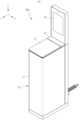
- FIG. 2 is a perspective view of the cup washer 1000 of FTG. 1 viewed from a rear upper side.
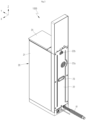
- FIG. 3 is a perspective view of the cup washer 1000 of FIG. 1 in the state in which a front panel 21 is removed
- the cup washer 1000 may be installed in government offices, companies, or stores.
- the above-mentioned personal cup or reusable cup may mean a cup (made of a glass or plastic material), a mug, a tumbler, or the like.
- the cup washer 1000 may have a tower shape that is long substantially in the vertical direction. Therefore, the floor area required for installation of the cup washer 1000 may be small compared to the total volume of the cup washer 1000.
- the cup washer 1000 may include a frame 10, a panel 20, a display unit 30, a tub 100, a spray unit 300, a water reservoir 50, a sump 60, a circulation pump 70, a drain pump 80, an additive storage part 500, an additive supply part 600, a drying part 400, and a controller 40.
- the controller 40 may integrally control the display unit 30, the circulation pump 70, the drain pump 80, and the additive supply part 600.
- the frame 10 may configure the framework of the cup washer 1000.
- the frame 10 may include a base frame 13, a front frame 11, a rear frame 12, and a horizontal frame 14.
- the base frame 13 may configure the lowermost portion of the cup washer 1000.
- the base frame 13 may be seated on the ground.
- the front frame 11 and the rear frame 12 may define a shape extending upward from the edges of the base frame 13.
- the horizontal frame 14 may interconnect the front frame 11 and the rear frame 12 in the horizontal direction.
- the panel 20 may be coupled to the frame 10 to isolate the components of the cup washer 1000 from the external environment
- the panel 20 may include a front panel 21, a rear panel 22, a door 25, and a storage unit cover 26.
- the front panel 21 may be coupled to the frame 10 to define the front surface and both side surfaces of the cup washer 1000 under the door 25.
- the rear panel 22 may be coupled to the frame 10 to define the rear surface of the cup washer 1000 below the display unit 30.
- a vent 22a may be provided in the rear panel 22. Outside air may flow into the drying part 400 through the vent 22a
- An air outlet 22b may be provided in the rear panel 22. Air from the drying part 400 may be discharged to the outside through the air outlet 22b.
- a handle 23 may be provided on the rear panel 22. A manager may easily move the cup washer 1000 by holding the handle 23.
- the display unit 30 may be provided in the upper portion of the cup washer 1000.
- the screen of the display unit 30 may face the front side of the cup washer 1000. Therefore, the user of the cup washer 1000 may visually check the screen of the display unit 30 from the front side of the cup washer 1000.
- the display unit 30 may output the operating state of the cup washer 1000, such as "wash”, "rinse", and "dry".
- the water reservoir 50 is able to store water.
- the water reservoir 50 may be heavier than other components.
- the water reservoir 50 may be coupled to the top surface of the base frame 13. Therefore, the overall center of gravity of the cup washer 1000 may be lowered Therefore, even when the cup washer 1000 is configured in a tower shape that is long substantially in the vertical direction, the possibility of the cup washer 1000 falling over may be reduced
- a heater and a temperature sensor may be provided in the water reservoir 50.
- the heater may heat the water in the waterreservoir 50.
- the controller 40 may control the heater by receiving a signal from the temperature sensor.
- the water in the water reservoir 50 may be supplied into the tub 100 through the washing water supply part 90.
- the washing water supply part 90 may include a washing water supply pipe 91 and an opening/closing valve 92.
- the controller 40 may control the opening/closing valve 92.
- the user may select a washing mode through the screen of the display unit 30.
- a washing mode through the screen of the display unit 30.
- the user may select a "normal washing mode” or a "quick washing mode” through the screen of the display unit 30.
- the normal washing mode may refer to a mode in which a cup C is washed using a detergent and a rinse.
- the quick washing mode may refer to a mode in which a cup C is washed only by spraying water without a detergent or a rinse.
- the normal washing mode may include a normal washing step and a drying step.
- the water in the water reservoir 50 may be supplied into the tub 100 through the warring water supply part 90.
- the washing water supply part 90 may include a washing water supply pipe 91 and an opening/closing valve.
- the additive supply part 600 may supply the additive into the tub 100 for a set period of time. The additive may be mixed with water within the tub 100.
- the water mixed with the additive may flow into the sump 60 on the lower side of the tub 100 through the filter part 800 by gravity.
- the circulation pump 70 may press the water flowing into the sump 60 toward the first spray nozzle 310.
- the first spray nozzle 310 may spray the water mixed with the additive toward the inside and outside of the cup C.
- the circulation pump 70 may supply water flowing into the sump 60 into the tub 100 through the washing water spray unit 95.
- the washing water spray unit 95 may spray the water mixed with the additive toward the cup lid Ca
- the circulation pump 70 may operate for a set period of time. When the set period of time elapses, the water flowing into the sump 60 may move to a drain pipe 81 through the drain pump 80 and may be drained out of the cup washer 1000 (completing of the normal washing step).
- the additive may include a first additive and a second additive.
- the first additive may be provided as a detergent
- the second additive may be provided as a rinse.
- the normal washing step may include a first normal washing step and a second normal washing step.
- the first normal washing step may be the step of washing the cup C with the water mixed with the first additive.
- the second normal washing step may be the step of washing the cup C with the watermixed with the second additive.
- the first normal washing step and the second normal washing step may be performed sequentially.
- the drying step may be performed.
- the drying part 400 may supply heated air into the tub 100. During this process, moistair within the tub 100 may be discharged to the outside.
- the drying step may beperformedfora set period of time (completing of the drying step).
- the second spray nozzle 320 may be connected to the water supply pipe.
- a three-way valve may be installed between the water supply pipe and the water reservoir 50.
- the second spray nozzle 320 may be connected to the water supply pipe through the three-way valve.
- An opening/closing valve may be provided between the second spray nozzle 320 and the three-way valve.
- the controller 40 may control the three-way valve and the open/close valve.
- the quick washing mode may include a quick washing step and a drying step.
- the second spray nozzle 320 may be connected to the water supply pipe through the three-way valve. In the quick washing mode, the additive may not be supplied into the tub 100.
- the second spray nozzle 320 may spray water not mixed with the additive into the cup C.
- the opening/closing valve may open the flow path between the water supply pipe and the second spray nozzle 320 for a set period of time. When the set period of time elapses, the water flowing into the sump 60 may move to a drain pipe 81 through the drain pump 80 and may be drained out of the cup washer 1000 (completing of the quick washing step).
- the drying step may be performed.
- the drying part 400 may supply heated air into the tub 100. During this process, moistair within the tub 100 may be discharged to the outside.
- the drying step may beperformedfora set period of time (completing of the drying step).
- FIG. 8 is a partial perspective view of the cup washer 1000 of FIG. 1 , illustrating the state in which the storage unit cover 26 is opened
- FIG. 9 is a partial rear view of the cup washer 1000 of FTG. 5, illustrating the tub 100, the additive storage part 500, and the additive supply part 600.
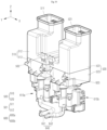
- FIG. 10 is a perspective view illustrating the additive storage part 500 and the additive supply part 600 of FIG. 9 .
- the additive storage part 500 may be provided behind the tub 100.
- the additive storage part 500 may be coupled to the tub 100 by a coupling member such as a bolt.
- Bolt coupling portions 503 where coupling members are coupled to the additive storage part 500 and the tub 100 may be formed.
- the additive storage part 500 may store an additive Ag in an inner portion thereof (hereinafter, referred to as a "storage space 501").
- the additive Ag may include a first additive Ag1 and a second additive Ag2.
- the first additive Ag1 may be provided as a detergent
- the second additive Ag2 may be provided as a rinse.
- the additive storage part 500 may include a first additive storage part 510 and a second additive storage part 520.
- the first additive storage part 510 may store the first additive Ag1 inside an inner portion thereof (hereinafter, referred to as a "first storage space511").
- the first additive storage part 510 may have an opening (hereinafter. referred to as"first additive inlet")at the upper end thereof The user may fill the first additive Ag 1 into the first storage space 511 through the first additive inlet
- An additive discharge hole 502 may be provided in the lower portion of the first additive storage part 510.
- the second additive storage part 520 may store the second additive Ag2 in the inner portion thereof (hereinafter, referred to as a "second storage space 521").
- the second additive storage part 520 may have an opening (hereinafter, referred to as a "second additive inlet”) at the upper end thereof The user may fill the second additive Ag2 into the second storage space 521 through the second additive inlet
- An additive discharge hole 502 may be provided in the lower portion of the second additive storage part 520.
- the storage unit cover 26 may simultaneously open or close the first additive inlet and the second additive inlet
- the top panel 24 may isolate the components inside the front panel 21 from the external environment at the upper end portion of the front panel 21, except for the cup inlet and the additive inlets.
- the edge portion (hereinafter, referred to as a "cover edge portion") of the storage unit cover 26 may be bent downward. In the state in which the cover edge portion seated on the top panel 24, the storage unit cover 26 may simultaneously close the first additive inlet and the second additive inlet
- the first additive storage part 510 may include a first upper storage unit 512 and a first lower storage unit 513.
- the first upper storage unit 512 may define the upper portion of the first storage space 511.
- the first lower storage unit 513 may define the lower portion of the first storage space 511.
- the lower end portion of the first upper storage unit 512 and the upper end portion of the first lower storage unit 513 may be bonded to each other by adhesive, heat fusion, or the like.
- a floater and a floater sensor may be installed in the first storage space 511.
- the floater may be floated by the first additive Ag1.
- the floater sensor may detect the height of the floater.
- the controller 40 may receive a signal from the floater sensor.
- the controller 40 may output the amount of the first additive Ag1 on the screen of the display unit 30.
- the second additive storage part 520 may include a second upper storage unit 522 and a second lower storage unit 523.
- the second upper storage unit 522 may define the upper portion of the second storage space 521.
- the second lower storage unit 523 may define the lower portion of the second storage space 521.
- the lower end portion of the second upper storage unit 522 and the upper end portion of the second lower storage unit 523 may be bonded to each other by adhesive, heat fusion, or the like.
- the first upper storage unit 512 and the second upper storage unit 522 may be symmetrical with respect to the virtual YZ plane. Therefore, with respect to the X-axis direction, the first additive inlet and the second additive inlet may be spaced apart from each other (see FIG. 8 ).
- the additive Ag may include a first additive Ag1 and a second additive Ag2.
- the normal washing step may include a first normal washing step and a second normal washing step.
- the first normal washing step may be the step of washing the cup C with the water mixed with the first additive Ag1.
- the second normal washing step may be the step of washing the cup C with the water mixed with the second additive Ag2.
- the controller 40 may individually control the first additive supply part 600a and the second additive supply part 600b. Accordingly, the controller 40 may sequentially perform the first normal washing step and the second normal washing step. That is, after completing the washing of the cup C using the first additive Ag1 (first normal washing step), the controller 40 may perform the washing of the cup C using the second additive Ag2 (second normal washing step).
- the first additive supply part 600a and the second additive supply part 600b may be manufactured in the same form, except for the lengths of the additive transfer pipes 640.
- the first additive supply part 600a and the second additive supply part 600b may be manufactured in the same manufacturing process, and the first additive supply part 600a and the second additive supply part 600b may be separated depending on the assembly locations thereof Therefore, the manufacturing process of the additive supply part 600 can be simplified.
- the additive supply part 600 should be understood to mean the first additive supply part 600a and the second additive supply part 600b.
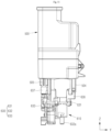
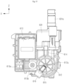
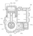
- FIG. 11 is a side view illustrating the additive storage part 500 and the additive supply part 600 of FIG. 10 .
- FIG. 12 is a side view illustrating the additive pump 610 of FIG. 10 .
- FIG. 13 is a view illustrating the additive pump 610 of FIG. 12 , in which the illustration of the cover housing 633 is omitted
- the pump housing 630 may provide an accommodation space therein.
- the accommodation space may mean the space that accommodates the piston 611, the rotary plate 612, the additive motor 613, and the connecting rod 614.
- the pump housing 630 may be coupled under the additive storage part 500.
- a first cover fastening portion 636 may be provided on the pump housing 630, and a first storage part fastening portion 504 may be provided on the lower portion of the additive storage part 500.
- the first cover fastening portion 636 may be coupled to the first storage part fastening portion 504.
- the first cover fastening portion 636 and the first storage part fastening portion 504 may be detachably coupled with a quick release buckle structure.
- a second cover fastening portion 637 may be provided on the pump housing 630, and a second storage part fastening portion 505 may be provided on the lower portion of the additive storage part 500.
- the second cover fastening portion 637 may be coupled to the second storage part fastening portion 505.
- the second cover fastening portion 637 and the second storage part fastening portion 505 may be detachably coupled with a bolt fastening structure.
- the pump housing 630 may include a body housing 631 and a cover housing 633.
- a plurality of protrusions may be provided on the body housing 631.
- a plurality of engagement portions may be provided on the edge of the cover housing 633.
- the cover housing 633 may move forward (right in FIG. 11 ) to allow the engagement portions are engaged with the protrusions. Therefore, the cover housing 633 may be coupled to the body housing 631 (see FIG. 12 ). In this case, the cover housing 633 may close the accommodation space. When the engagement portions are separated from the protrusions, the cover housing 633 may be separated from the body housing 631 (see FIG. 13 ). Therefore, the cover housing 633 may open the accommodation space.
- the additive motor 613 may be coupled to the body housing 631.
- the rotary plate 612 may be coupled to the body housing 631 to be rotatable about the center shaft 612a.
- the additive motor 613 may transmit rotational power to the rotary plate 612 through a transmission gear 613b.
- the transmission gear 613b and the rotary plate 612 may be connected by a spur gear.
- a shaft (hereinafter referred to as a "motor shaft") of the additive motor 613 and the transmission gear 613b may be connected by a worm and a worm gear.
- the worm may be provided on the motor shaft, and the worm gear may be provided on the transmission gear 613b.
- the transmission of motion from the worm to the worm gear is possible, but the transmission of motion from the worm gear to the worm is not possible. Therefore, the rotation of the motor shaft may be blocked when the motor shaft is stopped (when the controller 40 does not operate the additive motor 613). Therefore, the controller 40 may block the additive Ag from moving into the tub 100 when the additive motor 613 does not operate. In addition, the change in the pumped amount of additive Ag due to the change in the operating speed of the piston 611 due to unintended external factors may be minimized
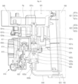
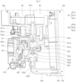
- the additive pump 610 may include a magnetic force member 615 and a magnetic force detector 616 (see FIG. 13 ).
- the magnetic force member 615 may be coupled to one surface of the rotary plate 612. Therefore, the magnetic force member 615 may rotate along the circumferential direction of the rotary plate 612 around the center shaft 612a by the additive motor 613.
- the magnetic force member 615 may be a permanent magnet
- the magnetic force member 615 may be a bar magnet with different poles at opposite both ends.
- one pole of the bar magnet may face the center shaft 612a, and the other pole may face the opposite side. That is, on one surface of the rotary plate 612, the length direction of the bar magnet may coincide with the radial direction of the rotary plate 612 (see FIG. 13 ).
- Magnetic flux refers to the number of magnetic force lines passing vertically through a surface.
- a magnet has a high density of magnetic force lines at opposite end poles. Therefore, the magnetic force member 615 may form the maximum magnetic flux in the radial direction of the rotary plate 612 on one surface of the rotary plate 612.
- the magnetic force detector 616 may be equipped with a Hall sensor to detect the magnetic field of the magnetic force member 615.
- the magnetic force detector 616 may be a linear Hall sensor or a switch Hall sensor.
- the linear Hall sensor may provide a continuous output voltage that changes linearly depending on the strength of the magnetic field.
- the switch Hall sensor may provide a digital output that switches between two states depending on the presence or absence of a magnetic field.
- a detector insertion portion can be provided in the cover housing 633.
- the magnetic force detector 616 may be inserted into the detector insertion portion
- the magnetic force detector 616 may be provided on one side of the rotation path of the magnetic force member 615 centered on the center shaft 612a of the rotary plate 612, and may detect the maximum magnetic flux of the magnetic force member 615.
- the magnetic force detector 616 may be connected to the controller 40. Therefore, the controller 40 may detect the rotation of the rotary plate 612 using the magnetic force detector 616. The controller 40 may control the input amount of the additive Ag in response to a signal from the magnetic force detector 616. For example, the controller 40 may stop the additive motor 613 when receiving a signal from the magnetic force detector 616 N times after rotating the additive motor 613. Therefore, the controller 40 can precisely control the amount of additive Ag supplied into the tub 100.
- a cup washer 1000 detects the rotation of the rotary plate 612 using a Hall sensor.
- the accuracy of the pumped amount of additive Ag can be increased by precisely controlling the position of the piston 611. Therefore, the variation in the pumped amount caused by the change in the operating speed of the piston 611 due to external factors can be minimized.
- the restrictions of the piston 611 due to external factors may be identified through position detection by the Hall sensor.
- the pump housing 630 may have a first additive supply pipe 631a in the upper portion thereof.
- the first additive supply pipe 621 may be provided in the form of a circular hollow pipe that is long substantially in the vertical direction
- the first additive supply pipe 631a may connect the lower portion of the additive storage part 500 to the suction space of the additive pump 610.
- An additive discharge hole 502 may be provided in the lower portion of the additive storage part 500 into which the first additive supply pipe 631a is inserted in the vertical direction.
- the inner surface of the additive discharge hole 502 may have a long cylindrical shape in the vertical direction.
- the first additive supply pipe 631a may be inserted into the additive discharge hole 502 by moving upward from the bottom of the additive storage part 500. Therefore, the first additive supply pipe 631a may be coupled to the additive storage part 500.
- the upper end of the first additive supply pipe 631a may be slightly higher than the lowest portion of the storage space 501.
- the opening of the first supply passage 631b may be open not only upward but also laterally.
- the opening of the first supply passage 631b may have substantially the same height as the lowest portion of the storage space 501. Therefore, almost all of the additive Ag filled in the storage space 501 may move to the first supply passage 631b by gravity.
- the pair of sealing members 631c may doubly prevent leakage of the additive Ag through the space between the outer surface of the first additive supply pipe 631a and the inner surface of the additive discharge hole 502. Therefore, the leakage of the additive Ag through the space between the outer surface of the first additive supply pipe 631a and the inner surface of the additive discharge hole 502 can be blocked
- the pump housing 630 may have a second additive supply pipe in the lower portion
- the second additive supply pipe 632a may be provided in the form of a circular hollow pipe that is long substantially in the vertical direction
- the second additive supply pipe 632a may connect the connecting space 635 of the additive pump 610 to the additive transfer pipe 640.
- the additive transfer pipe 640 may connect the pump housing 630 and the tub 100 so that the additive Ag discharged from the suction space 634 moves to the tub 100.
- the additive transfer pipe 640 may be connected to the tub 100 below the connecting space 635. Therefore, the additive transfer pipe 640 can supply the additive Ag into the tub 100 from below the connecting space 635. Therefore, the additive Ag discharged from the additive pump 610 can move to the outlet of the additive transport pipe 640 by gravity.
- the additive supply part 600 may include a first check valve 621, a second check valve 622, and a third check valve 623.
- the second check valve 622 may include an outlet plug 622a, an outlet elastic member 622b, and an outlet guide bar 622c.
- An outlet elastic member 622b may be provided in the connecting space 635.
- the outlet elastic member 622b may be elastically deformed in the vertical direction.
- the outlet elastic member 622b may be a compression spring.
- the lower end of the outlet elastic member 622b may be located at the lower end of the connecting space 635.
- the outlet elastic member 622b may push the outlet plug 622a toward the outlet of the suction space 634 by its own elastic force.
- the fluid in the suction space 634 may move to the upper space 634a (see FIG. 16 ). Therefore, the pressure of the suction space 634 may decrease during the downward stroke.
- the first check valve 621 may open the inlet of the suction space 634. Therefore, the additive Ag of the storage space 501 can flow into the suction space 634 through the first supply passage 631b.
- the second check valve 622 may open the outlet of the suction space 634. Therefore, the additive Ag in the suction space 634 can flow into the connecting space 635. Therefore, as the pressure inside the additive transfer pipe 640 increases during the upward stroke, the third check valve 623 can open the outlet of the additive transfer pipe 640. Therefore, the additive supply part 600 may discharge the additive Ag into the inside of the tub during the upward stroke.
- the suction space 634 may be disposed below the storage space 501. Therefore, all of the additive Ag in the storage space 501 can flow into the suction space 634 through the inlet of the suction space 634 by gravity.
- the connecting space 635 may be disposed below the suction space 634. Therefore, all of the additive Ag in the suction space 634 can flow into the connecting space 635 through the outlet of the suction space 634 by gravity.
- the additive transfer pipe 640 may be disposed below the connecting space 635. Therefore, all of the additive Ag in the connecting space 635 can move toward the outlet of the additive transferpipe 640 by gravity. Therefore, all of the additiveAg stored in the storage space 501 can be discharged into the tub.
- FIG. 18 is a view of a washing space inside the tub 100 of FIG. 6 viewed from a front upper side.
- the washing water supply part 90 may supply water to a specific region (hereinafter, referred to as a "first region 104") on the inner wall of the tub 100.
- the additive inlet 103 may be provided in the first region 104 of the innerwall of the tub 100.
- the first region 104 may be located between the first additive supply part 600a and the second additive supply part 600b with respect to the X-axis.
- the first additive transfer pipe 641 may connect the second additive supply pipe 632a of the first additive supply part 600a to the tub 100.
- the first additive transfer pipe 641 may be connected to the tub 100 below the connecting space. Therefore, the first additive transfer pipe 641 can supply the first additive Ag1 to the inside of the tub 100 below the connecting space. Therefore, almost all of the additive Ag discharged from the additive pump 610 of the first additive supply part 600a can move to the inside of the tub 100 by gravity.
- the first additive transfer pipe 641 may be connected to the first additive inlet 103a in the inner wall of the tub 100. That is, the first additive supply part 600a may supply the first additive Ag1 to the inside of the tub 100 through the first additive inlet 103a
- the first additive inlet 103a may be provided in the first region 104 of the inner wall of the tub 100.
- the second additive transfer pipe 642 may connect the second additive supply pipe 632a of the second additive supply part 600b to the tub 100.
- the second additive transfer pipe 642 may be connected to the tub 100 below the connecting space. Therefore, the second additive transfer pipe 642 can supply the second additive Ag2 to the inside of the tub 100 below the connecting space. Therefore, almost all of the additive Ag discharged from the additive pump 610 of the second additive supply part 600b can move to the inside of the tub 100 by gravity.
- the second additive transfer pipe 642 may be connected to the second additive inlet 103a on the inner wall of the tub 100. That is, the second additive supply part 600b may supply the second additive Ag2 into the tub 100 through the second additive inlet 103b.
- the second additive inlet 103b may be provided in the first region 104 of the inner wall of the tub 100.
- the first region 104 may be located between the first additive supply part 600a and the second additive supply part 600b with respect to the X-axis.
- the first additive Ag1 may be a detergent.
- the second additive Ag2 may be a rinse.
- the second additive transfer pipe 642 may have a shorter length than the first additive transfer pipe 641. Therefore, even when the second additive Ag2 is supplied in a smaller amount than the first additive Ag1, almost all of the second additive Ag2 can move into the tub 100 without remaining inside the second additive transfer pipe 642.
- the washing water supply pipe 91 may be connected to a washing water inlet 102 on the inner wall of the tub 100.
- the washing water inlet 102 may be located above the additive inlet 103 within the first region 104.
- the water discharged from the washing water inlet 102 may fall toward the additive inlet 103 by gravity. Accordingly, the washing water supply part 90 can supply water to the first region 104. Therefore, the additive Ag discharged into the tub 100 from the additive inlet 103 can be mixed with the water discharged from the washing water inlet 102 and move downward together with the water.
- the first additive inlet 103a and the second additive inlet 103b may be spaced apart from each other in the horizontal direction within the firstregion 104. With respect to the X-axis, the first additive inlet 103a and the second additive inlet 103b may be spacedapart from the washing water inlet 102 at equal intervals in the horizontal direction
- the first additive Ag 1 discharged from the first additive inlet 103a into the tub 100 can be mixed with the water discharged from the washing water inlet 102.
- the second additive Ag2 discharged from the second additive inlet 103b into the tub 100 may be mixed with the water discharged from the washing water inlet 102.
Landscapes
- Washing And Drying Of Tableware (AREA)
Applications Claiming Priority (2)
| Application Number | Priority Date | Filing Date | Title |
|---|---|---|---|
| KR20240001378 | 2024-01-04 | ||
| KR1020240100197A KR20250107090A (ko) | 2024-01-04 | 2024-07-29 | 컵세척기 |
Publications (1)
| Publication Number | Publication Date |
|---|---|
| EP4581999A1 true EP4581999A1 (de) | 2025-07-09 |
Family
ID=92816588
Family Applications (1)
| Application Number | Title | Priority Date | Filing Date |
|---|---|---|---|
| EP24200695.5A Pending EP4581999A1 (de) | 2024-01-04 | 2024-09-17 | Becherwäscher |
Country Status (2)
| Country | Link |
|---|---|
| US (1) | US20250221603A1 (de) |
| EP (1) | EP4581999A1 (de) |
Citations (8)
| Publication number | Priority date | Publication date | Assignee | Title |
|---|---|---|---|---|
| EP0593876B1 (de) * | 1992-10-08 | 1997-04-02 | Bosch-Siemens HausgerÀ¤te GmbH | Vorrichtung zum Spülen von Spülgut |
| KR100830487B1 (ko) | 2001-07-24 | 2008-05-21 | 엘지전자 주식회사 | 드럼세탁기의 세제 공급장치 |
| US8833605B2 (en) * | 2010-07-20 | 2014-09-16 | Ecolab Usa Inc. | Product delivery and monitoring system |
| KR101474433B1 (ko) | 2008-04-10 | 2014-12-19 | 엘지전자 주식회사 | 세탁기의 세제 공급 장치 |
| US20170042404A1 (en) * | 2015-08-10 | 2017-02-16 | Arcelik Anonim Sirketi | Dishwasher |
| IT201900016853A1 (it) * | 2019-09-20 | 2021-03-20 | Idm Packaging S R L | Apparecchiatura e metodo di lavaggio per contenitori |
| WO2022226015A1 (en) * | 2021-04-23 | 2022-10-27 | Illinois Tool Works Inc. | Dishwasher, in particular in the form of a counter module for a counter system |
| US20230414059A1 (en) * | 2021-04-23 | 2023-12-28 | Illinois Tool Works Inc. | Dishwasher, in particular in the shape of a counter module for a counter system |
Family Cites Families (5)
| Publication number | Priority date | Publication date | Assignee | Title |
|---|---|---|---|---|
| KR20110082761A (ko) * | 2010-01-12 | 2011-07-20 | 주식회사 대우일렉트로닉스 | 액체세제용 펌프장치 |
| KR102647316B1 (ko) * | 2016-12-23 | 2024-03-14 | 삼성전자주식회사 | 세탁기 |
| WO2020043102A1 (zh) * | 2018-08-29 | 2020-03-05 | 江苏雷利电机股份有限公司 | 洗涤剂投放装置和洗碗机 |
| US12264428B2 (en) * | 2019-06-24 | 2025-04-01 | Delaware Capital Formation, Inc. | Modular chemical dispenser and pump for same |
| KR20230127796A (ko) * | 2022-02-25 | 2023-09-01 | 삼성전자주식회사 | 세제공급장치 또는 이를 포함하는 세탁기 |
-
2024
- 2024-09-17 EP EP24200695.5A patent/EP4581999A1/de active Pending
- 2024-10-15 US US18/916,108 patent/US20250221603A1/en active Pending
Patent Citations (8)
| Publication number | Priority date | Publication date | Assignee | Title |
|---|---|---|---|---|
| EP0593876B1 (de) * | 1992-10-08 | 1997-04-02 | Bosch-Siemens HausgerÀ¤te GmbH | Vorrichtung zum Spülen von Spülgut |
| KR100830487B1 (ko) | 2001-07-24 | 2008-05-21 | 엘지전자 주식회사 | 드럼세탁기의 세제 공급장치 |
| KR101474433B1 (ko) | 2008-04-10 | 2014-12-19 | 엘지전자 주식회사 | 세탁기의 세제 공급 장치 |
| US8833605B2 (en) * | 2010-07-20 | 2014-09-16 | Ecolab Usa Inc. | Product delivery and monitoring system |
| US20170042404A1 (en) * | 2015-08-10 | 2017-02-16 | Arcelik Anonim Sirketi | Dishwasher |
| IT201900016853A1 (it) * | 2019-09-20 | 2021-03-20 | Idm Packaging S R L | Apparecchiatura e metodo di lavaggio per contenitori |
| WO2022226015A1 (en) * | 2021-04-23 | 2022-10-27 | Illinois Tool Works Inc. | Dishwasher, in particular in the form of a counter module for a counter system |
| US20230414059A1 (en) * | 2021-04-23 | 2023-12-28 | Illinois Tool Works Inc. | Dishwasher, in particular in the shape of a counter module for a counter system |
Also Published As
| Publication number | Publication date |
|---|---|
| US20250221603A1 (en) | 2025-07-10 |
Similar Documents
| Publication | Publication Date | Title |
|---|---|---|
| TWI613341B (zh) | 洗衣機 | |
| EP2476791B1 (de) | Reinigungsmittelgehäuse und Waschmaschine damit | |
| EP2930263A1 (de) | Waschmaschine | |
| CA2561674C (en) | Bulk dispensing system for washing machine | |
| KR20170099150A (ko) | 세탁기 및 그 제어방법 | |
| JP2019502070A (ja) | 排水制御機構及び洗濯機 | |
| CN112011963B (zh) | 一种洗衣机用衣物提升装置及滚筒洗衣机 | |
| CN107780159B (zh) | 用于衣物处理装置的洗涤剂投放系统以及衣物处理装置 | |
| CN107164925B (zh) | 滚筒式衣物处理装置 | |
| EP2612962A2 (de) | Waschmittelzuführungsvorrichtung und Waschmaschine damit | |
| EP4581999A1 (de) | Becherwäscher | |
| US20230272571A1 (en) | Detergent supply device and washing machine including the same | |
| EP2655715A1 (de) | Haushaltswaschmaschine | |
| EP4570158A1 (de) | Becherwäscher | |
| KR20250107090A (ko) | 컵세척기 | |
| EP1444394B1 (de) | Dosiervorrichtung für flüssigwaschmittel | |
| CN111850928B (zh) | 一种滚筒洗衣机 | |
| CN117822262A (zh) | 一种滚筒洗衣机 | |
| CN210066257U (zh) | 一种自动投放组件及洗衣机 | |
| KR101054104B1 (ko) | 식기 세척기의 에어 브레이크 구조 | |
| CN112754372B (zh) | 一种密封结构和自移动清洁机器人 | |
| ITTO20060280A1 (it) | Macchina lavabiancheria con dispensatore di agenti di lavaggio | |
| US20250043491A1 (en) | Tub cover with bumpers to absorb impacts in a washing machine appliance | |
| CN223041468U (zh) | 水箱组件及清洁装置 | |
| KR102537142B1 (ko) | 세탁기 |
Legal Events
| Date | Code | Title | Description |
|---|---|---|---|
| PUAI | Public reference made under article 153(3) epc to a published international application that has entered the european phase |
Free format text: ORIGINAL CODE: 0009012 |
|
| STAA | Information on the status of an ep patent application or granted ep patent |
Free format text: STATUS: REQUEST FOR EXAMINATION WAS MADE |
|
| 17P | Request for examination filed |
Effective date: 20241017 |
|
| AK | Designated contracting states |
Kind code of ref document: A1 Designated state(s): AL AT BE BG CH CY CZ DE DK EE ES FI FR GB GR HR HU IE IS IT LI LT LU LV MC ME MK MT NL NO PL PT RO RS SE SI SK SM TR |