EP4579958A2 - Elektrische anschlussklemme - Google Patents
Elektrische anschlussklemme Download PDFInfo
- Publication number
- EP4579958A2 EP4579958A2 EP25177442.8A EP25177442A EP4579958A2 EP 4579958 A2 EP4579958 A2 EP 4579958A2 EP 25177442 A EP25177442 A EP 25177442A EP 4579958 A2 EP4579958 A2 EP 4579958A2
- Authority
- EP
- European Patent Office
- Prior art keywords
- female terminal
- electrical female
- main body
- spring
- electrical
- Prior art date
- Legal status (The legal status is an assumption and is not a legal conclusion. Google has not performed a legal analysis and makes no representation as to the accuracy of the status listed.)
- Pending
Links
Images


Classifications
-
- H—ELECTRICITY
- H01—ELECTRIC ELEMENTS
- H01R—ELECTRICALLY-CONDUCTIVE CONNECTIONS; STRUCTURAL ASSOCIATIONS OF A PLURALITY OF MUTUALLY-INSULATED ELECTRICAL CONNECTING ELEMENTS; COUPLING DEVICES; CURRENT COLLECTORS
- H01R13/00—Details of coupling devices of the kinds covered by groups H01R12/70 or H01R24/00 - H01R33/00
- H01R13/40—Securing contact members in or to a base or case; Insulating of contact members
- H01R13/42—Securing in a demountable manner
- H01R13/428—Securing in a demountable manner by resilient locking means on the contact members; by locking means on resilient contact members
- H01R13/432—Securing in a demountable manner by resilient locking means on the contact members; by locking means on resilient contact members by stamped-out resilient tongue snapping behind shoulder in base or case
-
- H—ELECTRICITY
- H01—ELECTRIC ELEMENTS
- H01R—ELECTRICALLY-CONDUCTIVE CONNECTIONS; STRUCTURAL ASSOCIATIONS OF A PLURALITY OF MUTUALLY-INSULATED ELECTRICAL CONNECTING ELEMENTS; COUPLING DEVICES; CURRENT COLLECTORS
- H01R13/00—Details of coupling devices of the kinds covered by groups H01R12/70 or H01R24/00 - H01R33/00
- H01R13/02—Contact members
- H01R13/10—Sockets for co-operation with pins or blades
- H01R13/11—Resilient sockets
- H01R13/113—Resilient sockets co-operating with pins or blades having a rectangular transverse section
-
- H—ELECTRICITY
- H01—ELECTRIC ELEMENTS
- H01R—ELECTRICALLY-CONDUCTIVE CONNECTIONS; STRUCTURAL ASSOCIATIONS OF A PLURALITY OF MUTUALLY-INSULATED ELECTRICAL CONNECTING ELEMENTS; COUPLING DEVICES; CURRENT COLLECTORS
- H01R13/00—Details of coupling devices of the kinds covered by groups H01R12/70 or H01R24/00 - H01R33/00
- H01R13/02—Contact members
- H01R13/10—Sockets for co-operation with pins or blades
- H01R13/11—Resilient sockets
- H01R13/115—U-shaped sockets having inwardly bent legs, e.g. spade type
-
- H—ELECTRICITY
- H01—ELECTRIC ELEMENTS
- H01R—ELECTRICALLY-CONDUCTIVE CONNECTIONS; STRUCTURAL ASSOCIATIONS OF A PLURALITY OF MUTUALLY-INSULATED ELECTRICAL CONNECTING ELEMENTS; COUPLING DEVICES; CURRENT COLLECTORS
- H01R13/00—Details of coupling devices of the kinds covered by groups H01R12/70 or H01R24/00 - H01R33/00
- H01R13/02—Contact members
- H01R13/15—Pins, blades or sockets having separate spring member for producing or increasing contact pressure
- H01R13/187—Pins, blades or sockets having separate spring member for producing or increasing contact pressure with spring member in the socket
-
- H—ELECTRICITY
- H01—ELECTRIC ELEMENTS
- H01R—ELECTRICALLY-CONDUCTIVE CONNECTIONS; STRUCTURAL ASSOCIATIONS OF A PLURALITY OF MUTUALLY-INSULATED ELECTRICAL CONNECTING ELEMENTS; COUPLING DEVICES; CURRENT COLLECTORS
- H01R13/00—Details of coupling devices of the kinds covered by groups H01R12/70 or H01R24/00 - H01R33/00
- H01R13/62—Means for facilitating engagement or disengagement of coupling parts or for holding them in engagement
- H01R13/627—Snap or like fastening
- H01R13/6271—Latching means integral with the housing
-
- H—ELECTRICITY
- H01—ELECTRIC ELEMENTS
- H01R—ELECTRICALLY-CONDUCTIVE CONNECTIONS; STRUCTURAL ASSOCIATIONS OF A PLURALITY OF MUTUALLY-INSULATED ELECTRICAL CONNECTING ELEMENTS; COUPLING DEVICES; CURRENT COLLECTORS
- H01R13/00—Details of coupling devices of the kinds covered by groups H01R12/70 or H01R24/00 - H01R33/00
- H01R13/64—Means for preventing incorrect coupling
-
- H—ELECTRICITY
- H01—ELECTRIC ELEMENTS
- H01R—ELECTRICALLY-CONDUCTIVE CONNECTIONS; STRUCTURAL ASSOCIATIONS OF A PLURALITY OF MUTUALLY-INSULATED ELECTRICAL CONNECTING ELEMENTS; COUPLING DEVICES; CURRENT COLLECTORS
- H01R13/00—Details of coupling devices of the kinds covered by groups H01R12/70 or H01R24/00 - H01R33/00
- H01R13/02—Contact members
- H01R13/10—Sockets for co-operation with pins or blades
- H01R13/11—Resilient sockets
- H01R13/111—Resilient sockets co-operating with pins having a circular transverse section
-
- H—ELECTRICITY
- H01—ELECTRIC ELEMENTS
- H01R—ELECTRICALLY-CONDUCTIVE CONNECTIONS; STRUCTURAL ASSOCIATIONS OF A PLURALITY OF MUTUALLY-INSULATED ELECTRICAL CONNECTING ELEMENTS; COUPLING DEVICES; CURRENT COLLECTORS
- H01R13/00—Details of coupling devices of the kinds covered by groups H01R12/70 or H01R24/00 - H01R33/00
- H01R13/46—Bases; Cases
- H01R13/52—Dustproof, splashproof, drip-proof, waterproof, or flameproof cases
- H01R13/5205—Sealing means between cable and housing, e.g. grommet
-
- H—ELECTRICITY
- H01—ELECTRIC ELEMENTS
- H01R—ELECTRICALLY-CONDUCTIVE CONNECTIONS; STRUCTURAL ASSOCIATIONS OF A PLURALITY OF MUTUALLY-INSULATED ELECTRICAL CONNECTING ELEMENTS; COUPLING DEVICES; CURRENT COLLECTORS
- H01R4/00—Electrically-conductive connections between two or more conductive members in direct contact, i.e. touching one another; Means for effecting or maintaining such contact; Electrically-conductive connections having two or more spaced connecting locations for conductors and using contact members penetrating insulation
- H01R4/10—Electrically-conductive connections between two or more conductive members in direct contact, i.e. touching one another; Means for effecting or maintaining such contact; Electrically-conductive connections having two or more spaced connecting locations for conductors and using contact members penetrating insulation effected solely by twisting, wrapping, bending, crimping, or other permanent deformation
- H01R4/18—Electrically-conductive connections between two or more conductive members in direct contact, i.e. touching one another; Means for effecting or maintaining such contact; Electrically-conductive connections having two or more spaced connecting locations for conductors and using contact members penetrating insulation effected solely by twisting, wrapping, bending, crimping, or other permanent deformation by crimping
- H01R4/183—Electrically-conductive connections between two or more conductive members in direct contact, i.e. touching one another; Means for effecting or maintaining such contact; Electrically-conductive connections having two or more spaced connecting locations for conductors and using contact members penetrating insulation effected solely by twisting, wrapping, bending, crimping, or other permanent deformation by crimping for cylindrical elongated bodies, e.g. cables having circular cross-section
- H01R4/184—Electrically-conductive connections between two or more conductive members in direct contact, i.e. touching one another; Means for effecting or maintaining such contact; Electrically-conductive connections having two or more spaced connecting locations for conductors and using contact members penetrating insulation effected solely by twisting, wrapping, bending, crimping, or other permanent deformation by crimping for cylindrical elongated bodies, e.g. cables having circular cross-section comprising a U-shaped wire-receiving portion
- H01R4/185—Electrically-conductive connections between two or more conductive members in direct contact, i.e. touching one another; Means for effecting or maintaining such contact; Electrically-conductive connections having two or more spaced connecting locations for conductors and using contact members penetrating insulation effected solely by twisting, wrapping, bending, crimping, or other permanent deformation by crimping for cylindrical elongated bodies, e.g. cables having circular cross-section comprising a U-shaped wire-receiving portion combined with a U-shaped insulation-receiving portion
Definitions
- an electrical female terminal be provided with structural arrangements or features including; overstress protection using support members which prevent undesired deformation of the electrical female terminal; a shape having an orientation or polarity of the electrical female terminal as defined by a main body; a wire fastening feature using a wire fastening portion of the electrical female terminal for securing a wire; a locking feature using a tang member to fasten and assure the electrical female terminal is locked within a housing; a spring feature using a two-bodied spring which efficiently and resiliently connects the electrical female terminal with a male pin or male terminal, or further "blade-like” object; and a guiding feature using a guide member to direct and "self-correct" the male pin or male terminal, or further “blade-like” object into the electrical female terminal.
- the electrical female terminal of the present invention can accommodate and can receive a TPA device within a space above the wire fastening portion thereof and located behind the main body.
- the two-bodied spring of the present invention is "two-bodied” wherein the application or orientation uses a lower spring member and an upper spring member.
- the lower spring member and upper spring member operate in unison or together and in total, to provide a spring force applied to or acting upon to the male pin or male terminal, or further "blade-like" object, when one of such aforementioned objects is being inserted into the female electrical terminal.
- the lower spring member extends further along a lengthwise direction of the pin and further downward and towards a floor of the main body, than the upper spring member.
- the upper spring member and lower spring members are integrally structured with each other and connected by curved side members and folded one above the other.
- the lower spring member is below the upper spring member, and the upper spring member is above the lower spring member, respectively.
- the relationship between the unflexed orientation of the upper and the lower spring member is provided wherein they may or may not contact.
- the tang member may additionally provide a resistance against the upward movement of the lower spring member, thereby applying a resilient force against its upward travel, and consequently the tang member increases the total spring force of the spring.
- the above described orientations of the spring are provided to efficiently and resiliently connect and secure the electrical female terminal with the male pin or male terminal, or further "blade-like" object, as necessary and or in operation.
- the shape of the electrical female terminal of the present invention has an orientation or polarity that is maintained and ensured, and is provided in order to mate the electrical female terminal with a corresponding connector assembly, one which has an opening with a similar orientation or similar polarity to that of the electrical female terminal, respectively, for proper fitting and mating therewith.
- a protrusion extends from an unattached end portion of a lever member, the protrusion having faces angled relative to each other to efficiently deflect the lever member upwards when the protrusion interacts with an internal protrusion of a housing or a connector assembly, which in turn makes the electrical female terminal of this invention more difficult to remove from the housing or the connector assembly to thereby protect the electrical female terminal against the electrical female terminal from falling out during use.
- a top portion of the retainer member of the electrical female terminal of this invention, located above the two-bodied spring to have a dimple portion to increase the number of contacts to an upper spring of the two-bodied spring, so as to increase the stiffness of the two-bodied spring.
- the overstress feature which includes a protruding member, is located at an intermediate portion or a middle portion of the tang member.
- the overstress feature of the tang member includes a protruding member having a lower edge being substantially flat or extending along a substantially horizontal direction to improve quality control (i.e., easier to measure the structural and functional characteristics thereof) during the manufacturing of the electrical female terminal.
- the electrical female terminal is formed, substantially in its entirety, as a contiguous and continuous single construction. That is, the electrical female terminal of this invention is formed as a contiguous and continuous single construction having included therein, but not limited thereto, as contiguous and continuous parts: at least the main body, the two-bodied spring, and the wire fastening portion and/or the lever member (or tang member), along with the neck member that joins the main body and the wire fastening portion. Also, there is no part or section of the electrical female terminal of this invention that is welded, soldered, or brazed to the electrical female terminal.
- the electrical female terminal for mating with a male pin or male terminal or further "blade-like" object as well as mating and locking with a connector assembly.
- the electrical female terminal generally includes a main body, a two-bodied spring, and a wire fastening portion.
- the main body of the electrical female terminal has a shape or form that is substantially box-shaped, whereby a portion of the main body is formed into a box like orientation.
- the main body generally includes an upper and a lower main body, a tang member and the two-bodied spring.
- the tang member includes a lever member which locks the electrical female terminal within the connector assembly.
- the lever member has a protruding member which meets another protruding member, extending from the main body, when the lever member is flexed. Both protruding members act as an overstress protection for the lever member; i.e., to prevent or protect the lever member from becoming deformed when the electrical female terminal is being mated with the connector assembly.
- Another protruding member extends from the lever member to protect the two-bodied spring from becoming overstressed.
- the main body is also comprised of a support member at both front and back ends thereof, which prevent overstress and deformation of the electrical female terminal.
- a protrusion extends from an unattached end portion of the lever member, the protrusion having faces angled relative to each other to efficiently deflect the lever member upwards when the protrusion interacts with an internal protrusion of a housing or a connector assembly, which in turn makes the electrical female terminal of this invention more difficult to remove from the housing or the connector assembly to thereby protect the electrical female terminal against the electrical female terminal from falling out during use.
- a top portion of the retainer member of the electrical female terminal of this invention, located above the two-bodied spring, has a dimple portion to increase the number of contacts to an upper spring of the two-bodied spring, so as to increase the stiffness of the two-bodied spring.
- the terminal face or leading end portion of the electrical female terminal is prevented from damaging or cutting a silicone seal, which seals the connector assembly from environmental contaminants, during mating therewith by providing thereon a recessed top face portion and a recessed bottom face portion.
- the overstress feature which includes a protruding member, is located at an intermediate portion or a middle portion of the tang member.
- a protruding member having a lower edge being substantially flat or extending along a substantially horizontal direction to improve quality control (i.e., easier to measure the structural and functional characteristics thereof) during the manufacturing of the electrical female terminal.
- the two-bodied spring is substantially located within a passageway PW of the main body, and includes two members, which act or operate to create a spring force which can be applied to a male pin or male terminal, or further "blade-like" object, when one of such aforementioned objects is being inserted into the female electrical terminal.
- the electrical female terminal of this invention also has an orientation or polarity which is maintained and ensured for proper fitment into a corresponding connector assembly.
- the connector assembly has an opening with a similar orientation or similar polarity which is also maintained for proper fitting with the electrical female terminal.
- the electrical female terminal is formed, substantially in its entirety, as a contiguous and continuous single construction. That is, the electrical female terminal of this invention is formed as a contiguous and continuous single construction having included therein, although not limited thereto, as contiguous and continuous parts: at least the main body, the two-bodied spring, and the wire fastening portion and/or the lever member (or tang member), along with the neck member that joins the main body and the wire fastening portion. Also, there is no part or section of the electrical female terminal of this invention that is welded, soldered, or brazed to the electrical female terminal.
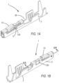
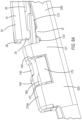
- FIG. 1A shows a front top perspective view of the electrical female terminal, generally referred to as reference number 1.
- the electrical female terminal 1 is integrally formed as a continuous piece, being folded, creased, or curved, to form a single construct, and one which includes a main body 5, a two-bodied spring 130, and a wire fastening portion 3.
- the main body 5 further includes a tang member 15.
- the wire fastening portion 3 may be of a foldable crimp or clamping type as shown here, but may further be of an insulation displacement contact (IDC) type, or other similarly formed wire fastening means being integrally formed and preferably extending substantially with or in the lengthwise direction of the electrical female terminal 1, and more specifically extending from a rear portion of the main body 5 of the electrical female terminal 1 which is able to interact with an wire insulation portion 120 and or wire core portion 110 of the electrical wire or cable 100 to securely connect the electrical wire or cable 100 to the electrical female terminal 1.
- IDC insulation displacement contact
- an additional or sole wire fastening of the electrical wire or cable 100 to the electrical female terminal 1 may be accomplished by including means of creating a secure and or an electrically conductive fastening by including but not limited to, for example, welding, brazing, soldering and or other similar means.
- the wire fastening portion 3 transitions to and is integrally formed with and to the main body 5 by a neck member 52 (see also, FIGS. 3A, 3B ).
- the tang member 15 includes a lever member 25, the lever member 25 having an unattached end portion 28 and an attached end portion 30.
- the lever member 25, is shown here in a normal, relaxed state.
- the lever member 25 is resiliently biased to the normal relaxed state whereby, it is not being influenced by outside contact, and whereby the point of subsequent flex of lever member 25 may occur at the attached end portion 30 when the unattached end portion 28 is moved.
- the unattached end portion 28 of the lever member 25 preferably has, in a cross-section along a width thereof, a substantially U-shaped form, or the like, although the form or shape thereof is not restricted thereto (see, FIGS.
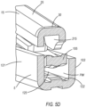
- the attached end portion 30 of the lever member 25 preferably has, a substantially U-shaped form or the like (see, e.g., FIG. 5D ), although the form thereof is not restricted thereto.
- An upper portion 200a of the main body 5 similarly has a substantially U-shaped form or the like (see, e.g., FIG. 6C), although the form or shape thereof is not restricted thereto.
- the lever member 25 has a protruding member 35, which meets another protruding member 37 that extends from the main body 5 (see, FIGS. 1B , 2B , and 8A ).
- Both protruding members 35, 37 act as an overstress protection for the lever member 25. That is, the protruding members 35, 37 impinge against each other, when the lever member 25 is in a flexed state. This form thereby prevents or protects the lever member 25 from becoming deformed when the female terminal 1 contacts or mates with a connector assembly 90 or the like (see also, FIG. 10A and 10B ).
- the lever member 25 is operative to substantially move between a flexed state and a normal, relaxed state whereby it may return to the normal, relaxed state without being substantially deformed, or be inoperable, and still able to secure the female electrical terminal 1 with a connector housing 90, as discussed later ( FIGS. 10A , 10B ).
- the protruding members 35, 37 are preferably substantially rectangular, round, trapezoid, or the like (see also, FIGS. 4 , 8A ), although the shape or form thereof is not restricted thereto.
- the unattached end portion 28 of the lever member 25 is freely pushed downward and moves from the normal relaxed state, to a flexed state (that is, the protruding member 35 approaches the another protruding member 37) (see, FIG. 10A ).
- the unattached end portion 28 of the lever member 25 freely moves upward, with a return to a normal, relaxed state of the lever member 25 (that is, the protruding member 35 moves away from the another protruding member 37 and when the lever member 25 is resiliently biased back to its normal, relaxed state) (see, FIGS. 2A , 10B ).
- the unattached end portion 28 is preferably thereby impinged onto a member (not shown) inside the connector assembly 90, locking and securing therein the electrical female terminal 1.
- a member not shown
- Such a structural arrangement which has the unattached end portion 28 of the lever member 25 impinged inside the connector assembly 90, acts as a locking and securing feature of the electrical female terminal 1 with the connector assembly 90 (see, FIG. 10B ).
- the lever member 25 and the unattached end portion 28 may be further freely movable in an upward direction away from the normal, relaxed state, and flex away from a floor 122 of main body 5, and as will be discussed later, if the lever member 25 is flexed upward this may result in a resistance in a direction back to the normal relaxed state of the lever member 25. If the two-bodied spring 130 pushes or contacts the lever member 25 to the aforementioned flexed state, the lever member 25 can act upon the two-bodied spring 130 and add to the spring force of the two-bodied spring 130. This, notably, when the two-bodied spring 130 is flexed upward and away from the floor 122 and makes contact the lever member 25 and more specifically as the two-bodied spring 130 interacts with a male pin or male terminal, or further "blade-like" object.
- a protruding member 36 also extends from a side of the lever member 25.
- Protruding member 36 is located substantially above, and further may engage with, a lower spring member 133, and even further provide overstress protection for the lower spring member 133, and generally the two-bodied spring 130, as will be discussed in more detail later (see, e.g., FIGS. 1A , 2A , 6A and 8A ).
- the protruding member 36 moves freely and unobstructed within the movement of the lever member 25, when the lever member 25 moves in a downward travel from its normal, relaxed state, into a flexed state toward the two-bodied spring 130 and a floor 122 of the main body 5.
- Protruding member 36 is preferably substantially rectangular, round, trapezoid, or the like (see, FIG. 6A ), although the shape or form thereof is not restricted thereto. Additionally, and with respect to the side of the lever member 25 from which protruding member 35 extends, protruding member 36 extends on an opposite side thereof of lever member 25, as well as on a different portion and having a different orientation with respect to the side of the lever member 25 from which the protruding member 35 extends, more specifically, the protruding member 36 is closer to the attached end portion 30 and the protruding member 35 is closer to the unattached end portion 28 when comparing their location along the lever member 25 (see, FIGS. 4 , 6A , and 8A ).
- the protruding member 36 and the protruding member 35 are positioned along the lever member 25 wherein they are neither mirror images, nor directly opposed, and further thus do not have portions thereof, respectively, which are mirror images or directly opposed, therefore no portions thereof of protruding member 36 and protruding member 35 overlap along the lengthwise direction of the electrical female terminal 1 (see, FIGS. 2A, 2B ).
- the wire fastening portion 3 of the electrical female terminal 1 has a space or transition area 50 above the neck member 52.
- the space or transition area 50 is located at a front portion 51 of the wire fastening portion 3, and behind the main body 5.
- TPA terminal position assurance
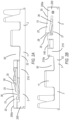
- FIG. 2D is a cross-sectional view illustrating a surface area located on a rear portion of the lower spring member 133, of the electrical female terminal 1. Specifically, the surface area on a rear portion of the lower spring member 133 of the main body 5, may engage with the terminal position assurance (TPA) device 300.
- TPA terminal position assurance
- the rear portion of the lower spring member 133 provides an added interface area or interference surface for the electrical female terminal 1 for it to interact with, and or contact, and thereby interfere with the TPA device 300 when the TPA device 300 is inserted thereinto the space or transition area 50, further assuring that the electrical female terminal 1 remains locked, secured, and correctly positioned within the connector assembly 90 and preventing the electrical female terminal 1 from being removable, ejected, slidably removable or slidably ejected from the connector assembly 90, in use and in operation (see, e.g., FIG. 2C ).
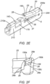
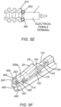
- the electrical female terminal 1 of this invention further includes a protrusion 150 extending from the unattached end portion 28 of the lever member 25, as shown in FIG. 2E .
- the unattached end portion 28 of the lever member 25 preferably has side end portions 28a and a center end portion 28b.
- the protrusion 150 preferably extends from the center end portion 28b, although such a structural arrangement is not limited thereto. That is, the protrusion 150 is not limited to extending from the center end portion 28b of the end portion 28 of the lever member 25, and may also extend from the side end portion 28a of the end portion 28 of the lever member 25.
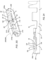
- FIG. 4 Illustrated in FIG. 4 is the tang member 15 and the attached end 30 and unattached end portion 28 of the lever member 25 thereof. As previously discussed with respect to FIGS. 2A and 2B , FIG. 4 further illustrates the protruding member 35 of the unattached end portion 28 of the lever member 25, which is capable of impinging against another protruding member 37 that extends from the main body 5 (more particularly, extending from a lower portion 250 of the main body 5) in preventing the lever member 25 from being deformed when the lever member 25 is flexed.
- the attached end portion 30 of the lever member 25 is attached to an upper portion 200a of main body 5 (see also, FIG. 8B ). Also shown in FIG. 4 is an aperture 113 passing through a side member 121 of the main body 5 for accommodating therein, for support, a support member 115 of an upper guide member 105, as more fully discussed below (see, e.g., FIGS. 5A , 5B ).
- the overstress feature which includes a protruding member 235, is located at a substantially intermediate portion or a substantially middle portion of the tang member 15, as shown in FIG. 4A .
- An angled bottom portion 240 at the unattached end portion 28 of the tang member 15 of the lever member 25 is similarly shown in FIG. 4A to accommodate the protruding member 235 being located at a substantially intermediate or at a substantially middle portion of the tang member 15.
- Such a structural arrangement improves interaction with the tip of the tang member 15 when the electrical female terminal 1 of this invention is in use.
- FIG. 4A further illustrates the protruding member 235 of the unattached end portion 28 of the lever member 25, which is capable of impinging against another protruding member 237 that extends from the main body 5 (more particularly, extending from a lower portion 250 of the main body 5) in preventing the lever member 25 from being deformed when the lever member 25 is flexed.
- the just-described alternative structural arrangement protects the lever member 25 from being overstressed (and thereby prevented from being deformed, over-flexed or inoperable to lock the terminal with connector assembly 90) when the lever member 25 is pushed downward toward the lower portion 250 of the main body 5 and two-bodied spring 130, upon the electrical female terminal 1 entering or slidably entering into the connector assembly 90.
- the front opening 125 of the main body 5 is shown in FIG. 5A .
- the front opening 125 is defined by the front end portion 200, having a floor 122, a side member 103, a side member 121, and the upper guide member 105.
- side member 121 includes the aperture 113, passing through the side member 121, and for accommodating the support member 115 of the upper guide member 105.
- FIG. 5B is a cross-sectional view taken along line 5B-5B in FIG. 5A .
- the aperture 113 substantially accommodates therein the support member 115.
- the support member 115 integrally extends from the upper guide member 105 and in a direction perpendicular to the lengthwise direction of the electrical female terminal 1.
- the support member 115 ensures that the upper guide member 105 remains properly oriented, and stably supported by and within the main body 5 an front opening 125.
- the support member 115 also prevents the deformation of the front opening 125 and stable orientation of the front end portion 200, floor 122, side member 103, side member 121, with respect to the upper guide member 105, further to ensure the shape, polarity or orientation, of the main body 5 is not disrupted by the insertion of the male pin or male terminal, or further "blade-like" object (not shown).
- a substantially hump-like member 120 extending upward from the floor 122, which is further discussed in more detail below.
- FIGS. 5A and 5B Further displayed in FIGS. 5A and 5B is a passageway PW which extends through the lengthwise direction of the electrical female terminal 1 and main body 5 and is defined by the front opening 125, the front end portion 200 (which defines the front opening 125 as described previously), and the space surrounded by the inner surfaces of a lower portion 250 of the main body 5.
- the passageway PW therefore is able to accommodate therein the male pin or male terminal, or further "blade-like" object.
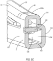
- FIG. 5C is a cross-sectional view taken along line 5C-5C of the electrical female terminal 1 in FIG. 5A , which illustrates a substantially U-shaped configuration or shape across an upper portion 200a of the main body 5 and a support member 215 at a front end portion 200 of the main body 5 of the electrical female terminal 1 of this invention.
- the configuration or shape of the cross-section across the upper portion 200a of the main body 5 and the support member 215 at the front end portion 200 of the main body 5 of the electrical female terminal 1 is substantially U-shaped.
- a connector system is sealed from environmental contaminants by utilizing silicone seals 310.
- the electrical female terminal 1 of this invention must pass through a silicone seal 310, as shown in the schematic view of FIG. 5E ; and during this process, the silicone seal 310 becomes vulnerable to damage or cuts at locations 303, 305 of the silicone seal 310.
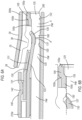
- a recessed top face portion 300 and a recessed bottom face portion 400 are provided, as illustrated in FIG. 5F .
- the recessed top face portion 300 and the recessed bottom face portion 400 spread out the interference between the electrical female terminal 1 of this invention and the silicone seal 310 at a larger distance, along the length of the recessed top face portion 300 or the recessed bottom face portion 400.
- the recessed top face portion 300 includes top 303, side 305, and bottom 307 portions, as illustrated in FIG. 5G and as more fully discussed below.
- the recessed top face portion 300 includes a top portion 303, side portions 305, and a bottom portion 307 located at the front ends or leading portions of the first support member 215 and the upper portion 200a.
- the recessed top face portion 300 may take the shape or form as illustrated in FIGS. 5F and 5G , the shape or form of the recessed top face portion 300 is not limited thereto, and may take any desired shape or form with the objective of preventing any damage or cutting of the silicone seal 310 during mating therewith.
- the shape or form of the recessed top face portion 300 may be a flat surface recess, as illustrated in FIG. 5H , or may be a concave surface recess, as illustrated in FIGS. 5I and 5J . As shown in the top view of FIG. 5J , the top portion 303 is shown to curve in a concave form or shape.
- the male pin or male terminal, or further "blade-like” object may lose contact with the first substantially level portion 105a, a second substantially inclined portion 105b respectively (and depending on the size of the male pin or male terminal or further “blade-like” object, it may lose contact with the third substantially level portion 105c) as the male pin or male terminal, or further "blade-like” object becomes oriented in a substantially level or perpendicular orientation to ⁇ with the topmost surface of the substantially hump-like member 120.
- the resilient force applied by the lever member 25, in the direction of return to its normal, relaxed state is in a direction opposite the movement of the end portion 135 of lower spring member 133 when making contact with the lever member 25 and or protruding member 36, and thereby, increases the spring force of the two-bodied spring 130 in a downward direction towards the floor 122, or the male pin or male terminal or further "blade-like" object under the two-bodied spring 130, and even more specifically directed to an apex A of the two-bodied spring 130, as will be discussed below.
- the space 160 becomes enlarged or expansive wherein the two-bodied spring 130 moves in an upward direction, away from the floor 122, while further interacting with the male pin or male terminal (not shown).
- the two-bodied spring 130 moves in an upward direction, away from the floor 122, and this increases the distance between the substantially curved portion 137, and the topmost surface of the hump-like member 120, and thus increases the space 160.
- the substantially curved portion 137 at its apex A, provides preferably for a single point of contact between the two-body spring 130 and an inserted male pin or male terminal (not shown), within space 160.
- top retainer member 140 maintains the folded construction of the two-bodied spring 130 by preventing the upper spring member 131 and lower spring member 133 from being unfurled, unfolded, substantially separated, or deformed as the two-bodied spring 130 is in a normal, unflexed state, or is in a flexed state wherein spring force is exerted against a male pin or male terminal (not shown).
- the front end tip 150, of the end portion 135 of the lower spring member 133 is to be in line or above the lower surface 155 of the second level portion 105c of the upper guide member 105.
- This orientation ensures the male pin or male terminal (not shown) passing through the front opening 125 is effectively guided by the upper guide member 105 and the end portion 135 of the lower spring member 133, along the substantially curved portion 137, and passes through a space 160 between the curved portion 137 of the lower spring 133 and the substantially hump-like member 120 (see also, FIG. 6A ).
- the front end tip 150 of the end portion 135 of the lower spring member 133 is to be in line or above the lower surface 155 of the second level portion 105c of the upper guide member 105 so as to prevent the lower spring member 133 from being impinged or oriented whereby unfavorably the male pin or male terminal passes between the lower surface 155 of the second level portion 105c and the end portion 135 of the lower spring member 133, and or into the gap or space created there between the aforementioned portions when the male pin or male terminal is inserted in an angled orientation with respect to a lengthwise direction of the electrical female terminal 1.
- the upper spring member 131 and the lower spring member 133 of the two-bodied spring 130 are integrally structured with each other and connected by curved side members 170, 133a, and folded one above the other, with the upper spring member 131 being above the lower spring member 133 respectively.
- the two-bodied spring 130 is preferably substantially parallel in a lengthwise direction of electrical female terminal 1 to the floor 122 (also see, FIG. 6A ).
- the upper spring member 131 and lower spring member 133 may also be oriented whereby they contact in full or in part along the lengthwise direction of the electrical female terminal 1 to the floor 122. As further shown in FIG.
- the upper and lower spring members 131, 133 are integrally connected by the curved side member 170 of the two-body spring member 130 (also see FIG. 8A ).
- the curved side member 170 is accommodated, at least in part, within a window or opening 180 of the main body 5.
- the curved side portion 133a of the main body 5 which integrally connects the lower spring member 133 to the lower portion 250 of the main body 5 (also see, FIG. 8B ).
- the curved side member 170 and curved side portion 133a may further influence and allow the resultant spring force of the two-bodied spring 130 to be further dependent or optimized upon the aspects of thickness, length, or radius of curvature etc. of the curved side member 170 and or curved side portion 133a, both respectively.
- a portion of the lower spring member 133 is movable unobstructed in an upward direction, away from the floor 122, until a portion of the lower spring member 133 contacts protruding member 36 of the lever member 25.
- the two-bodied spring 130 will be initially flexed in the upward direction and away from the floor 122, by a male pin or male terminal (not shown), and initially and preferably occurring when the lever member 25 is in a normal unflexed orientation to allow the lower spring member 133 the greatest distance of travel between the floor 122 and the protruding member 36.
- the lower spring member 133 has the end portion 135 which is a portion of the lower spring member 133 projected upward or inclined towards the upper main body 200a and lever member 25.
- FIG. 8B Illustrated in FIG. 8B are both the front and the back end portions 200, 210 of the main body 5, having a first support member 215 and a second support member 220, respectively. More particularly, an upper portion 200a at a front end portion 200 of the main body 5 includes the first support member 215, while the upper portion 210a at the back end portion 210 of the main body 5 includes the second support member 220. A gap 230 may separate the first support member 215 from a lower portion 250 of the main body 5. A gap 240 may separate the second support member 220 from the lower portion 250 of the main body 5.
- the first support member 215 and the second support member 220 are resiliently pushed downward toward, and may substantially contact, the lower portion 250 of the main body 5 through the gaps 230, 240, respectively, which may eliminate the gaps 230, 240.
- the gaps 230, 240 may not exist before the electrical female terminal 1 enters the connector assembly 90, wherein the first support member 215 and second support member 220 are fully contacting the lower portion 250 of the main body 5.
- the first and second support members 215, 220 provide structural resilience and rigidity to the main body 5, providing a support for the upper portions 200a, 210a of the main body by providing an available interface surface thereof facing the lower portion 250 of the main body 5.
- the first and second support members 215, 220 prevent the electrical female terminal 1 of this invention from being overstressed or deformed and as well as when being fitted into the connector assembly 90 and in use (see FIGS. 10A , 10B ).
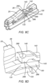
- FIG. 8C shows an alternative embodiment of the electrical female terminal 1 of this invention having the top retainer member 140, which is adjacent to the retainer member 142 and located above the two-bodied spring 130, with a dimple portion 280 to increase the number of contacts to the upper spring 131 of the two-bodied spring 130, so as to increase the stiffness of the two-bodied spring 130. That is, the first contact 143 with the upper spring member 131 is provided beneath the retainer member 142, while the second contact 286 with the upper spring member 131 is provided beneath an extended lower portion 285 beneath the dimple portion 280. As more particularly illustrated in FIG.
- the extended lower portion 285 beneath the dimple portion 280 is the extended lower portion 285, the extended lower portion 285 being in direct contact with the upper spring member 131 of the two-body spring 130 and providing the second contact 286 with the upper spring member 131. Also shown in FIG. 8D is the dimple portion 280 in a substantially angled cup-like shape, although the shape of the dimple portion 280 may take any form or shape, as shown (and not limited thereto) in FIGS. 8E and 8F , as alternative embodiments of the dimple portion 281.
- the dimple portion 281 may take a substantially V-shaped form. Further shown in FIG. 8E , the first contact 143 with the upper spring member 131 is provided beneath the retainer member 142, while the second contact 291 with the upper spring member 131 is provided beneath an extended lower portion 290 beneath the dimple portion 281. That is, as more particularly illustrated in FIG. 8E , beneath the dimple portion 281 is the extended lower portion 291, which directly contacts the upper spring member 131 of the two-body spring 130 and provides the second contact 291 with the upper spring member 131, thereby advantageously increasing the stiffness of the two-bodied spring 130.
- the dimple portion 282 may take a substantially cup-like form.
- the first contact 143 with the upper spring member 131 is provided beneath the retainer member 142
- the second contact 296 with the upper spring member 131 is provided beneath an extended lower portion 295 beneath the dimple portion 282. That is, as more particularly illustrated in FIG. 8F , beneath the dimple portion 282 is the extended lower portion 295, which directly contacts the upper spring member 131 of the two-bodied spring 130 and provides the second contact 296 with the upper spring member 131.
- dimple portion (as in dimple portions 280, 281, 282) will vary in size and location of the dimple portion within the top retainer member 140 of the retainer member 142.
- the second contacts 286, 291, 296 with the upper spring member 131 of the two-bodied spring 130 in addition to the first contact 143 with the upper spring member 131 provided beneath the retainer member 142, advantageously increase the stiffness of the two-bodied spring 130.
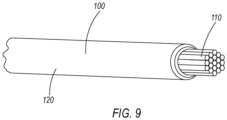
- FIG. 9 illustrates an exemplary electrical wire or cable 100 having the wire core portion 110 and the wire insulation portion 120, which are accommodated onto the electrical female terminal 1 of this invention.
- the priority or order of accommodation of the wire insulation portion 120 and the wire core portion 110 of electrical wire or cable 100 with the electrical female terminal 1 is not limited. thereto one embodiment of the wire fastening portion 3.
- the wire fastening portion 3 shown in this invention is one such embodiment of a wire fastening portion 3, but the current invention is not limited to this embodiment.
- the wire fastening portion 3 may be of a foldable crimp or clamping type as shown, but further may be an insulation displacement contact (IDC) type, or other similarly formed wire fastening means being integrally formed with a rear portion and preferably extending substantially with or in the lengthwise direction of the electrical female terminal 1, more specifically extending from the rear portion of the main body 3 of the electrical female terminal 1, and preferably able to interact with the wire insulation portion 120 and wire core portion 110 of the electrical wire or cable 100 to securely connect the electrical wire or cable 100 to the electrical female terminal 1.
- IDC insulation displacement contact
- the fastening of the electrical wire or cable 100 to the electrical female terminal 1 may include means of creating a secure and electrically conductive wire fastening including but not limited to welding, brazing, soldering and or other similar means.
- This invention is further not limited to the steps of insertion of the electrical wire or cable 100, wherein, the wire insulation portion 120 can be inserted first and the wire core portion 110 can be inserted second, and vice versa, and both may occur simultaneously depending on the structure and features of the wire fastening portion 3.
- the electrical female terminal 1 After or once the electrical wire or cable 100, having the wire insulation portion 120 and the wire core portion 110 thereof, is securely attached or inserted onto the electrical female terminal 1 by wire fastening means of the wire fastening portion 3 to the electrical female terminal 1, the electrical female terminal 1 is then in condition to be inserted into the connector assembly 90 or the like, as illustrated in FIGS. 10A and 10B .
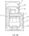
- FIG. 10A Illustrated in FIG. 10A is the electrical female terminal 1, in a pre-lock position, while being inserted into the connector assembly 90 or the like, the electrical female terminal 1 being shown in a front elevational view.
- the electrical female terminal is inserted into the corresponding connector assembly 90, the lever member 25 is consequently positively pushed downward by contact with the connector assembly 90 or by a user or device, to allow the electrical female terminal 1 to move further into, and be further inserted into the connector assembly 90.
- the protruding members 35, 37 see, e.g., FIGS.
- FIG. 10B shows the fully inserted electrical female terminal 1 into the connector assembly 90.
- the lever member 25 retracts upward to a normal, relaxed state and is further preferably locked or secured at the unattached end portion 28 by a member (not shown) inside the connector assembly 90.
- the TPA device 300 is then able to be accommodated within the space 50 located above the neck member 52 and behind the main body 5, thereby assuring that the electrical female terminal 1 remains locked, secured, and correctly positioned within the connector assembly 90.
- the upper portions 200a, 210a and the lower portion 250 of the main body 5 are in such polarity or orientation, so as to assure correct orientation of the electrical female terminal 1 for accurate insertion and fitting of the present electrical female terminal 1 of this invention inside an upper portion 90a and a lower portion 90b of the connector assembly 90, respectively.
- FIGS. 10A and 10B are the upper portion 90a and the lower portion 90b of the connector assembly 90 or the like.
- the orientation or polarity of the electrical female terminal 1 of this invention is such that when the electrical female terminal 1 of this invention is oriented, inserted, and fitted with the connector assembly 90, the upper portion 200a at the front end portion 200 and the upper portion 210a at the back end portion 210 (see, FIG. 8B ) of the main body 5 are respectively accommodated by the upper portion 90a of the connector assembly 90, while the lower portion 250 (see, FIG. 8B ) of the main body 5 is respectively accommodated by the lower portion 90b of the connector assembly 90.
- 10A and 10B of the electrical female terminal 1 of this invention are such that the upper portions 200a, 210a of the main body 5 will reside or fit within the narrower upper portion 90a. Further here the upper portion 200a and upper portion 210a are offset to one side in comparison to the lower portion 250 of the main body 5. The lower portion 250 is wider than the upper portions 200a, 210a and resides within the wider lower portion 90b of the connector assembly 90.
- such structural orientations or polarities of the electrical female terminal 1 of this invention, when inserted or fitted into the connector assembly 90 are not limited thereto.
Landscapes
- Connector Housings Or Holding Contact Members (AREA)
Applications Claiming Priority (5)
| Application Number | Priority Date | Filing Date | Title |
|---|---|---|---|
| US202163209796P | 2021-06-11 | 2021-06-11 | |
| US17/401,869 US12451635B2 (en) | 2021-06-11 | 2021-08-13 | Electrical female terminal |
| US17/575,423 US11699869B2 (en) | 2021-06-11 | 2022-01-13 | Electrical female terminal |
| PCT/US2022/012968 WO2022260716A1 (en) | 2021-06-11 | 2022-01-19 | An electrical female terminal |
| EP22750990.8A EP4352828A4 (de) | 2021-06-11 | 2022-01-19 | Elektrische anschlussklemme |
Related Parent Applications (2)
| Application Number | Title | Priority Date | Filing Date |
|---|---|---|---|
| EP22750990.8A Division EP4352828A4 (de) | 2021-06-11 | 2022-01-19 | Elektrische anschlussklemme |
| EP22750990.8A Division-Into EP4352828A4 (de) | 2021-06-11 | 2022-01-19 | Elektrische anschlussklemme |
Publications (2)
| Publication Number | Publication Date |
|---|---|
| EP4579958A2 true EP4579958A2 (de) | 2025-07-02 |
| EP4579958A3 EP4579958A3 (de) | 2025-10-01 |
Family
ID=84390708
Family Applications (3)
| Application Number | Title | Priority Date | Filing Date |
|---|---|---|---|
| EP22750990.8A Pending EP4352828A4 (de) | 2021-06-11 | 2022-01-19 | Elektrische anschlussklemme |
| EP25176099.7A Pending EP4576448A3 (de) | 2021-06-11 | 2022-01-19 | Elektrische anschlussklemme |
| EP25177442.8A Pending EP4579958A3 (de) | 2021-06-11 | 2022-01-19 | Elektrische anschlussklemme |
Family Applications Before (2)
| Application Number | Title | Priority Date | Filing Date |
|---|---|---|---|
| EP22750990.8A Pending EP4352828A4 (de) | 2021-06-11 | 2022-01-19 | Elektrische anschlussklemme |
| EP25176099.7A Pending EP4576448A3 (de) | 2021-06-11 | 2022-01-19 | Elektrische anschlussklemme |
Country Status (4)
| Country | Link |
|---|---|
| US (1) | US11699869B2 (de) |
| EP (3) | EP4352828A4 (de) |
| JP (1) | JP7748947B2 (de) |
| WO (1) | WO2022260716A1 (de) |
Families Citing this family (2)
| Publication number | Priority date | Publication date | Assignee | Title |
|---|---|---|---|---|
| JP7401500B2 (ja) * | 2020-10-13 | 2023-12-19 | ティーイー コネクティビティ ジャーマニー ゲゼルシャフト ミット ベシュレンクテル ハフツンク | 電気端子 |
| USD1108376S1 (en) * | 2023-12-14 | 2026-01-06 | J.S.T. Corporation | Electrical female terminal |
Citations (1)
| Publication number | Priority date | Publication date | Assignee | Title |
|---|---|---|---|---|
| US20210066836A1 (en) | 2019-08-29 | 2021-03-04 | J.S.T. Corporation | An electrical female terminal |
Family Cites Families (13)
| Publication number | Priority date | Publication date | Assignee | Title |
|---|---|---|---|---|
| JP3007781B2 (ja) | 1993-11-30 | 2000-02-07 | 矢崎総業株式会社 | 防水ゴム栓挿入用端子 |
| JP2003109718A (ja) | 2001-09-27 | 2003-04-11 | Sumitomo Wiring Syst Ltd | 雄側端子金具の製造方法及び雄側端子金具 |
| US6905376B2 (en) | 2003-04-15 | 2005-06-14 | J.S.T. Mfg. Co., Ltd. | Terminal |
| WO2007063193A1 (fr) | 2005-11-30 | 2007-06-07 | Fci | Contact electrique a dispositif de detrompage |
| DE102007049055B3 (de) * | 2007-10-11 | 2009-03-26 | Tyco Electronics Amp Gmbh | Vibrationsdämpfendes Kontaktelement |
| WO2014127817A1 (en) * | 2013-02-21 | 2014-08-28 | Delphi International Operations Luxembourg S.À.R.L. | Electrical terminal with a locking lance |
| DE102013223570B4 (de) | 2013-11-19 | 2021-06-24 | Te Connectivity Germany Gmbh | Stiftkontakt mit einem als Stanzbiegeteil gefertigten Kontaktkörper und einem massiven Kontaktstift |
| DE102015201381A1 (de) * | 2014-01-27 | 2015-07-30 | Hirschmann Automotive Gmbh | Kontaktelement |
| KR101913550B1 (ko) * | 2014-04-24 | 2018-10-30 | 몰렉스 엘엘씨 | 단자 설치부 |
| JP5907300B1 (ja) | 2015-04-30 | 2016-04-26 | 第一精工株式会社 | 導電端子 |
| JP6527633B2 (ja) | 2015-07-23 | 2019-06-05 | モレックス エルエルシー | 端子金具 |
| JP2017139213A (ja) * | 2015-11-30 | 2017-08-10 | タイコ エレクトロニクス (シャンハイ) カンパニー リミテッド | 接続ターミナルおよび接続アッセンブリ |
| DE102016125764A1 (de) * | 2016-12-28 | 2018-06-28 | Lear Corporation | Zweistückige elektrische clean-body-anschlussbuchse |
-
2022
- 2022-01-13 US US17/575,423 patent/US11699869B2/en active Active
- 2022-01-19 EP EP22750990.8A patent/EP4352828A4/de active Pending
- 2022-01-19 EP EP25176099.7A patent/EP4576448A3/de active Pending
- 2022-01-19 JP JP2022538877A patent/JP7748947B2/ja active Active
- 2022-01-19 EP EP25177442.8A patent/EP4579958A3/de active Pending
- 2022-01-19 WO PCT/US2022/012968 patent/WO2022260716A1/en not_active Ceased
Patent Citations (1)
| Publication number | Priority date | Publication date | Assignee | Title |
|---|---|---|---|---|
| US20210066836A1 (en) | 2019-08-29 | 2021-03-04 | J.S.T. Corporation | An electrical female terminal |
Also Published As
| Publication number | Publication date |
|---|---|
| US20220399668A1 (en) | 2022-12-15 |
| WO2022260716A1 (en) | 2022-12-15 |
| EP4576448A3 (de) | 2025-09-17 |
| EP4576448A2 (de) | 2025-06-25 |
| EP4579958A3 (de) | 2025-10-01 |
| EP4352828A4 (de) | 2025-06-25 |
| EP4352828A1 (de) | 2024-04-17 |
| JP7748947B2 (ja) | 2025-10-03 |
| US11699869B2 (en) | 2023-07-11 |
| JP2024521267A (ja) | 2024-05-31 |
Similar Documents
| Publication | Publication Date | Title |
|---|---|---|
| JP7641898B2 (ja) | メス型電気端子 | |
| KR100910717B1 (ko) | 횡방향 가요성 래치 부재가 형성된 전기 커넥터 어셈블리와 커넥터 위치 보장장치 | |
| JP4600874B2 (ja) | コネクタの端子及びコネクタ | |
| US5741162A (en) | Electrical contact having improved locking lances | |
| EP1617521B1 (de) | Anschlussbuchse | |
| EP4579958A2 (de) | Elektrische anschlussklemme | |
| GB2305785A (en) | Electrical receptacle terminal | |
| JP2008282807A (ja) | 電気コンタクト | |
| JPH1041018A (ja) | 短絡用端子金具 | |
| EP4560840A2 (de) | Elektrische anschlussklemme | |
| US6585544B2 (en) | Terminal fitting | |
| US20230198173A1 (en) | Electrical male terminal | |
| CN117378096A (zh) | 电气母端子 | |
| US12088051B2 (en) | Electrical male terminal | |
| WO2022271210A1 (en) | An electrical male terminal | |
| JP3444404B2 (ja) | 雌端子金具 | |
| WO2022271150A1 (en) | An electrical male terminal | |
| CN117397125A (zh) | 公电端子 |
Legal Events
| Date | Code | Title | Description |
|---|---|---|---|
| PUAI | Public reference made under article 153(3) epc to a published international application that has entered the european phase |
Free format text: ORIGINAL CODE: 0009012 |
|
| STAA | Information on the status of an ep patent application or granted ep patent |
Free format text: STATUS: THE APPLICATION HAS BEEN PUBLISHED |
|
| AC | Divisional application: reference to earlier application |
Ref document number: 4352828 Country of ref document: EP Kind code of ref document: P |
|
| AK | Designated contracting states |
Kind code of ref document: A2 Designated state(s): AL AT BE BG CH CY CZ DE DK EE ES FI FR GB GR HR HU IE IS IT LI LT LU LV MC MK MT NL NO PL PT RO RS SE SI SK SM TR |
|
| REG | Reference to a national code |
Ref country code: DE Ref legal event code: R079 Free format text: PREVIOUS MAIN CLASS: H01R0013110000 Ipc: H01R0013432000 |
|
| PUAL | Search report despatched |
Free format text: ORIGINAL CODE: 0009013 |
|
| AK | Designated contracting states |
Kind code of ref document: A3 Designated state(s): AL AT BE BG CH CY CZ DE DK EE ES FI FR GB GR HR HU IE IS IT LI LT LU LV MC MK MT NL NO PL PT RO RS SE SI SK SM TR |
|
| RIC1 | Information provided on ipc code assigned before grant |
Ipc: H01R 13/432 20060101AFI20250825BHEP Ipc: H01R 13/11 20060101ALI20250825BHEP Ipc: H01R 13/52 20060101ALN20250825BHEP Ipc: H01R 4/18 20060101ALN20250825BHEP |
|
| STAA | Information on the status of an ep patent application or granted ep patent |
Free format text: STATUS: REQUEST FOR EXAMINATION WAS MADE |
|
| 17P | Request for examination filed |
Effective date: 20260226 |