EP4579206A2 - Stomaleckerkennungssystem - Google Patents
Stomaleckerkennungssystem Download PDFInfo
- Publication number
- EP4579206A2 EP4579206A2 EP25172023.1A EP25172023A EP4579206A2 EP 4579206 A2 EP4579206 A2 EP 4579206A2 EP 25172023 A EP25172023 A EP 25172023A EP 4579206 A2 EP4579206 A2 EP 4579206A2
- Authority
- EP
- European Patent Office
- Prior art keywords
- trace
- leakage
- arc
- sensing accessory
- level
- Prior art date
- Legal status (The legal status is an assumption and is not a legal conclusion. Google has not performed a legal analysis and makes no representation as to the accuracy of the status listed.)
- Granted
Links
Images


Classifications
-
- G—PHYSICS
- G01—MEASURING; TESTING
- G01M—TESTING STATIC OR DYNAMIC BALANCE OF MACHINES OR STRUCTURES; TESTING OF STRUCTURES OR APPARATUS, NOT OTHERWISE PROVIDED FOR
- G01M3/00—Investigating fluid-tightness of structures
- G01M3/02—Investigating fluid-tightness of structures by using fluid or vacuum
- G01M3/04—Investigating fluid-tightness of structures by using fluid or vacuum by detecting the presence of fluid at the leakage point
- G01M3/16—Investigating fluid-tightness of structures by using fluid or vacuum by detecting the presence of fluid at the leakage point using electric detection means
-
- A—HUMAN NECESSITIES
- A61—MEDICAL OR VETERINARY SCIENCE; HYGIENE
- A61F—FILTERS IMPLANTABLE INTO BLOOD VESSELS; PROSTHESES; DEVICES PROVIDING PATENCY TO, OR PREVENTING COLLAPSING OF, TUBULAR STRUCTURES OF THE BODY, e.g. STENTS; ORTHOPAEDIC, NURSING OR CONTRACEPTIVE DEVICES; FOMENTATION; TREATMENT OR PROTECTION OF EYES OR EARS; BANDAGES, DRESSINGS OR ABSORBENT PADS; FIRST-AID KITS
- A61F5/00—Orthopaedic methods or devices for non-surgical treatment of bones or joints; Nursing devices ; Anti-rape devices
- A61F5/44—Devices worn by the patient for reception of urine, faeces, catamenial or other discharge; Colostomy devices
- A61F5/445—Colostomy, ileostomy or urethrostomy devices
-
- G—PHYSICS
- G01—MEASURING; TESTING
- G01M—TESTING STATIC OR DYNAMIC BALANCE OF MACHINES OR STRUCTURES; TESTING OF STRUCTURES OR APPARATUS, NOT OTHERWISE PROVIDED FOR
- G01M3/00—Investigating fluid-tightness of structures
- G01M3/02—Investigating fluid-tightness of structures by using fluid or vacuum
- G01M3/04—Investigating fluid-tightness of structures by using fluid or vacuum by detecting the presence of fluid at the leakage point
- G01M3/16—Investigating fluid-tightness of structures by using fluid or vacuum by detecting the presence of fluid at the leakage point using electric detection means
- G01M3/18—Investigating fluid-tightness of structures by using fluid or vacuum by detecting the presence of fluid at the leakage point using electric detection means for pipes, cables or tubes; for pipe joints or seals; for valves; for welds; for containers, e.g. radiators
- G01M3/186—Investigating fluid-tightness of structures by using fluid or vacuum by detecting the presence of fluid at the leakage point using electric detection means for pipes, cables or tubes; for pipe joints or seals; for valves; for welds; for containers, e.g. radiators for containers, e.g. radiators
- G01M3/187—Investigating fluid-tightness of structures by using fluid or vacuum by detecting the presence of fluid at the leakage point using electric detection means for pipes, cables or tubes; for pipe joints or seals; for valves; for welds; for containers, e.g. radiators for containers, e.g. radiators for flexible or elastic containers
Definitions
- the following description relates generally to a leakage detection system for medical devices, and more particularly to leakage detection system for ostomy appliances.
- An ostomy pouch system typically includes a pouch formed from opposing walls defining an internal collection area, an inlet opening for receiving a stoma, and an ostomy appliance for attaching the pouch to a user.
- the ostomy appliance may include, for example, an ostomy barrier of a one-piece pouch system, which is attached to a body-side pouch wall proximate an inlet opening, a baseplate for a two-piece pouch system configured to releasably engage a pouch, and a barrier ring.
- the ostomy appliance may include a skin barrier material for adhering to and sealing against user's peristomal skin surrounding the stoma.
- the level traces, the ground traces, and the arc traces may be arranged in eight substantially concentric layers substantially surrounding the center opening.
- the sensing accessory may be configured to measure a resistance of the medical device between the first level trace and the first ground trace, between the first ground trace and the second level trace, between each of the first, second, third, and fourth arc traces and the second ground trace, between the second ground trace and the fourth level trace, and between the fifth level trace and the third ground trace.
- Each of the first, second, third, and fourth arc traces may be arranged in a different quadrant in the sensor region.
- the first, second, third, and fourth arc traces may be arranged in intercardinal directions of the sensor region with the tail region being arranged at south.
- the first arc trace may extend along a southeast (SE) quadrant of the sensor region.
- the second arc trace may be formed from an exposed portion of a curved conductive trace extending along an east half of the sensor region, wherein a lower portion of the curved conductive trace may be covered with a masking layer to provide the second arc trace extending along a northeast (NE) quadrant of the sensor region.
- the severity of a leakage may increase from level 1 leakage to level 5 leakage, wherein level 1 leakage ⁇ level 2 leakage ⁇ level 3 leakage ⁇ level 4 leakage ⁇ level 5 leakage, wherein the level 5 leakage may be a critical leakage.
- the medical device may be an ostomy appliance including an adhesive layer configured for attachment to a peristomal skin of a user, wherein the plurality of sensors may be arranged adjacent the adhesive layer to measure a resistance of the adhesive layer.
- the sensing accessory may include a sensor layer having a body-side and a distal side, an adhesive layer arranged on the body-side of the sensor layer, and a backing layer arranged on the distal side of the sensor layer.
- the sensor layer may include a substrate, wherein the plurality of sensors may be provided on a body-side of the substrate and in contact with the adhesive layer.
- the sensing accessory may be configured to measure a resistance of the adhesive layer using the plurality of sensors.
- the backing layer may be formed from an adhesive.
- the sensing accessory may include a body-side release liner covering the adhesive layer and a distal side release liner covering the backing layer.
- Each of the release liners may include a tab configured to facilitate removal of the release liners, wherein the tabs may be arranged offset from each other.
- the release liners may include indicator labels to guide assembling of the sensing accessory with an ostomy appliance and attachment of the assembled sensing accessory and ostomy appliance to a user.
- exposed portions of the tail region of the sensor layer may be covered with a tail cover.
- the tail cover may also cover a portion of the connector region and include a wing-like extensions in the connector region, wherein an adhesive is provided on the wing-like extensions for attachment to an ostomy pouch or a user.
- the sensing accessory may be configured to attach to an ostomy barrier.
- the backing layer may be attached to the ostomy barrier, and the adhesive layer may be attached to a peristomal skin of a user.
- the adhesive layer may be formed from a hydrocolloid adhesive configured to exhibit a resistance drop from greater than 2 M ⁇ to about 1 k ⁇ when exposed to an ostomy effluent.
- the sensing accessory may be configured to stretch to conform to a convex ostomy barrier, wherein the substrate and the plurality of sensors may be formed from stretchable materials.
- a leakage detection system for an ostomy appliance may include the sensing accessory according to any of the foregoing embodiments and a wearable subsystem configured to communicate with the sensing accessory and receive signals from the sensing accessory to detect an ostomy effluent leakage.
- the wearable subsystem may include a hinged case comprising a bottom housing, a top housing, and a hinge connecting the bottom housing and the top housing.
- the hinged case may be configured to be closed after the wearable subsystem is connected to the connector region to secure the wearable subsystem to the sensing accessory.
- the sensing accessory may include a first alignment member and the wearable subsystem may include a second alignment member, which may be configured to engage with each other to facilitate correct alignment and connection between the sensing accessory and the wearable subsystem.
- the first alignment member may include at least one opening in the connector region of the sensing accessory, and the second alignment member may include at least one raised member, wherein the at least one raised member may be configured to be received in the at least one opening.
- the leakage detection system may include a charging dock configured to connect to the wearable subsystem to charge a rechargeable battery of the wearable subsystem.
- the charging dock may also be configured to wirelessly communicate with the wearable subsystem to receive leakage signals and send an alert to a user.
- the charging dock may comprise a housing configured to receive the wearable subsystem and charging pins.
- the wearable subsystem may include conductive pads configured to electrically connect to the charging pins.
- the charging dock may also include a device for generating a sound and/or light to alert a user and a wireless communication module for communicating with the wearable subsystem and/or a mobile application.
- the mobile application may be configured to provide means for a user to interact with the leakage detection system to set user's preferences for alerts and to review information about the ostomy appliance.
- the information may include leakage patterns, historical data of user's ostomy appliance usage, and/or ostomy appliance usage trends.
- the mobile application may also be configured to connect a user to ostomy training materials, experts at ostomy appliance suppliers, and/or ostomy clinicians. Further, the mobile application may be configured to check a connectivity between the mobile application and the wearable subsystem and/or a connectivity between the mobile application and the charging dock and alert a user.
- the mobile application may be configured to receive a leakage event information from the wearable subsystem and alert a user through alert functions of a mobile phone. Further, the mobile application may be configured to transmit data to a cloud server for storage and analysis to provide a prediction of a leakage event based on user's historical data, comparison data against leakage patterns of other users, product recommendations based on user's leakage patterns, and/or a prompt for re-ordering ostomy products. The mobile application may also be configured to manage a storage of photographs of user's stoma and/or peristomal skin for tracking with user's leakage patterns.
- An ostomy leakage detection system may be configured to detect ostomy effluent leakage under a skin barrier and alert a user.
- the ostomy leakage detection system can provide multiple benefits to the user. For example, the system may allow the user to intervene and change a skin barrier and/or ostomy pouch system before a leak progresses to cause embarrassment and inconvenience to the user. Further, the ostomy leakage detection system can assist in maintaining user's skin health by alerting a leakage in its early stage to prevent a prolonged skin exposure to ostomy effluent, which can lead to skin health complications.
- the ostomy leakage detection system can also support user's emotional well-being by reducing anxiety associated with a risk of leakage.
- the ostomy leakage detection system may comprise four subsystems - a sensing accessory, a wearable subsystem, a mobile application, and a charging dock.
- the sensing accessory may be provided as an accessory for an ostomy pouch system.
- the sensing accessory may include sensors for detecting the presence of ostomy effluent.
- the sensing accessory may be configured to communicates leakage detection signals to the wearable subsystem.
- the wearable subsystem may be configured to perform at least some processing of the leakage detection signals and alert a user of a leakage event.
- the wearable subsystem may be configured to communicate wirelessly with the mobile application.
- the mobile application may be a digital subsystem housed on a mobile device.
- the mobile application may be configured to process leak detection data and provide an alert or other information about an ostomy appliance to a user.
- the charging dock may be configured to recharge and communicate with the wearable subsystem and send out an alert, for example, when the system is in use at night.
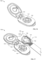
- FIG. 1 shows an ostomy leakage detection system 10 according to an embodiment.
- the ostomy leakage detection system 10 may generally comprise a sensing accessory 12, a wearable subsystem 14, a charging dock 16, and a mobile application (not shown).
- the sensing accessory 12 may be configured as an ostomy accessory that can be attached to an ostomy skin barrier, for example, an ostomy barrier of a one-piece pouch system or a faceplate for a two-piece pouch system.
- a one-piece ostomy pouch system 18 comprising an ostomy barrier 20 according to an embodiment is shown in FIG. 1 .
- the sensing accessory may be configured to detect an ostomy effluent leakage by providing sensors at a site of leakage under an ostomy barrier.
- the sensing accessory may comprise a plurality of sensors configured to detect the presence of fluid.
- the plurality of sensors may include conductivity sensors, thermistors, or other sensors.
- the sensing accessory may comprise a plurality of conductivity sensors formed from conductive traces arranged in close proximity.
- the conductive traces are also referred to herein as electrodes. When fluid bridges the conductive traces or saturates an adjacent hydrocolloid adhesive, a change in conductivity may be measured, which may be used to determine an ostomy effluent leakage.
- the sensors may be disposed on a circuit substrate.
- the circuit substrate may be configured to provide a suitable mechanical support to preserve the conductivity of the traces.
- the conductive traces may be formed by printing a circuit substrate using a conductive ink via a conventional printing process, for example, screen printing.
- the conductive ink may comprise carbon black, graphite, silver(Ag), or a silver and silver chloride blend (Ag/AgCl).
- Each of the plurality of conductive traces may have a width and arranged spaced apart from each other.
- the parameters of the conductive traces may be configured to provide a particular resistance of a sensor circuit.
- the sensing accessory may be configured to detect a leakage based on a change in resistance across a pair of conductive traces making up a sensor.
- FIG. 2 is a schematic cross-sectional illustration of two pairs of conductive traces configured to measure resistance of a skin barrier adhesive, wherein R1 is resistance between a first pair of conductive traces and R2 is resistance between a second pair of conductive traces.
- the leakage detection system may be configured to determine a leakage event from a decrease in resistance R2 between the second pair of conductive traces upon exposure to ostomy effluent.
- FIG. 3 is a graph displaying resistance data collected from a sensing accessory comprising a plurality of sensors according to an embodiment, wherein a drop of resistance is recorded at multiple sensors as a leakage progresses outward and contacts different sensors.
- the resistance drops from a value exceeding a measurement range of a processor (> 2 M ⁇ ) to very low (approximately 1 k ⁇ ).
- the resistance of the sensors may be negligible when compared to the large magnitude of a resistance change upon exposure to ostomy fluid.
- the sensors for the sensing accessory may be formed from conductive traces of various thicknesses and arrangements as long as the resistance of the conductive trace is low relative to the baseline (dry) resistance between the conductive traces.
- the sensing accessory 12 may comprise a plurality of sensors formed from a plurality of substantially elliptical conductive traces arranged around a center opening for receiving a stoma.
- substantially elliptical conductive traces as used herein include conductive traces having various elliptical shapes, such as circular, oval, etc.
- Each of the plurality of sensors may be arranged at different radial distances from the center opening.
- Each sensor may cover a portion of the area surrounding the central opening.
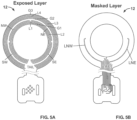
- the sensors may be arranged in five layers at different radial distances. Four sensor layers are labeled L1, L2, L3, and L4 as best shown in FIGS. 5A and 5C .
- FIG. 5A illustrates exposed portions of the conductive traces of the sensing accessory 12, while FIG. 5B illustrates masked portions of the conductive traces.
- the masking layer may be configured to promote adhesion between a hydrocolloid adhesive layer of a skin barrier and the sensing accessory 12.
- the sensor layer 15 may include sensors formed from an electrically conductive circuitry 24, such as a plurality of electrodes, conductive traces or the like.
- the electrically conductive circuitry 24 may be disposed on a circuit substrate 26.
- the sensor layer 15 may include a sensor region 28, a connector region 30 and a tail region 32 arranged therebetween.
- the electrically conductive circuitry 24 may be arranged in a predetermined pattern in the sensor region 28.
- the electrically conductive circuitry 24 may be generally arranged in a circular or semi-circular pattern. Other suitable patterns are envisioned as well, such as an oval or oblong pattern, or other closed or substantially closed loop pattern.
- the electrically conductive circuitry 24 in the sensor region 28 may be arranged at one or more radial distances from the center opening 19.
- the conductive circuitry 24 may comprise a plurality of electrically conductive traces arranged at a plurality of different, radial distances from the center opening 19.
- the tail region 32 may generally be formed as an elongated section extending from the sensor region 28 to the connector region 30.
- the tail region 32 may extend beyond an outer periphery of the first adhesive layer 13 and/or the barrier-side layer 17 in a direction radially outward from the center opening 19.
- the electrically conductive circuitry 24 may extend along the tail region 32.
- the tail region 32 may be flexible along at least a portion of its length such that it may be folded or wrapped.
- the connector region 30 may also include one or more alignment members 36.
- the one or more alignment members 36 may be configured to engage corresponding alignment members of the wearable subsystem 14 to facilitate positioning of the connector region 30 relative to the wearable subsystem 14 to ensure electrical connection therebetween.
- the one or more alignment members 36 of the connector region 30 may be an opening, recess or slot.
- the corresponding alignment members of the wearable subsystem 14 may be one or more projections configured for receipt in the opening, recess or slot of the connector region 30.
- the sensing accessory 12 may be configured to detect a leakage by measuring resistance between electrodes.
- the sensing accessory 12 may be configured to detect a change in resistance between electrodes triggered by ostomy effluent bridging the electrodes as a leakage propagates.
- the electrically conductive circuitry 24 may comprise a plurality of electrodes arranged on the proximal side of the sensor region 28, such that the electrodes may be positioned adjacent and in contact with the adhesive layer 13 to measure resistance of the adhesive layer 13.
- the plurality of electrodes 24 may extend along the proximal side of the tail region 32 and along a portion of the connector region 30 to the connection points 34.
- a masking element may be used to prevent shorting between electrodes in the areas where detection is not desired.
- a masking element 38 may be provided on the body-side of the sensing accessory 12 to cover the plurality of electrodes 24 in the tail region 32.
- FIG. 22 is a schematic illustration of the sensing accessory 12 attached to an ostomy barrier 20 and fitted around a stoma 2 according to an embodiment.
- the sensing accessory 12 may be configured such that a first conductive trace or electrode 25 of the electrically conductive circuitry 24 may be arranged adjacent a center opening 19 with a minimum space therebetween of about 0.25 inches to allow for fitting around the stoma 2 without damaging the electrically conductive circuitry 24.
- FIGS. 8 and 9 illustrate a sensing accessory 112 according to another embodiment.
- the sensing accessory 112 may be configured similar to the sensing accessory 12, generally comprising an adhesive layer 113, a sensor layer 115 and a barrier-side layer 117.
- the adhesive layer 113 may be formed from a hydrocolloid adhesive and disposed on a body-side of the sensing accessory 112 for attachment to a user.
- a release liner 121 including a tab 123 may be provided on the proximal side of the adhesive layer 113.
- the barrier-side layer 117 may be formed from an adhesive, and a release liner 122 including a tab 125 may be provided on a distal side of the barrier-side layer 117.
- the release liners 121, 122 may be arranged such that the tabs 123, 125 are offset from each other as best shown in FIG. 8 .
- Indicator labels 127, 129 may be provided on each side of the sensing accessory 112 to guide assembling of the sensing accessory 112 with an ostomy appliance and attachment of the same to a user.
- the sensor layer 115 may comprise a generally ring-shaped sensor region 128, a connector region 130 and a tail region 132 connecting the sensor region 128 and the connector region 130.
- the sensor region 128 may comprise sensors formed from an electrically conductive circuitry 124, which may extend through the tail region 132 and to connection points 134 in the connector region 130.
- the tail region 132 may be formed as an elongated section extending between the sensor region 128 and the connector region 130.
- the connection points 134 may be configured to electrical connect the sensing accessory 112 to an external device, such as the wearable subsystem 14.
- the exposed portions of the tail region 132 that are not covered by the adhesive layer 113 and the barrier-side layer 117 may be covered by tail covers 135, 137.
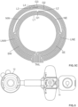
- FIG. 10 illustrates an electrically conductive circuitry 224 arranged on a proximal side of the sensor region 128 according to an embodiment.
- the electrically conductive circuitry 224 may comprise a plurality of substantially circular conductive traces, also referred to herein as circular electrodes, L1, L2, L4, L5, G1, G2, G3, and a plurality of arc shaped conductive traces, also referred to herein as electrode arcs, Q1, Q2, Q3, Q4.
- Each of the circular electrodes may be arranged at a different radial distance from a center opening 119 and configured to determine a radial progress of ostomy effluent leakage.
- the electrically conductive circuitry 224 may include four electrode arcs arranged in different sections of the sensor region 128 to determine a location of a leak in the sensor region 128.
- a first electrode arc Q1 may be arranged to extend along a southeast (SE) quadrant of the sensor region 128.
- a second electrode arc Q2 may be arranged to extend along an east half of the sensor region 128, wherein a lower portion of the second electrode arc Q2 that extends adjacent the first electrode arc Q1 may be covered with a making layer (similar to the masked LNE shown in FIG. 5B ), such that the exposed portion the second electrode arc Q2 only extends along a northeast (NE) quadrant of the sensor region 128.
- a third electrode arc Q3 may be arranged to extend along a west half of the sensor region 128, wherein a lower portion of the third electrode arc Q3 that extends adjacent a fourth electrode arc Q4 may be covered with a making layer (similar to the masked LNW shown in FIG. 5B ), such that the exposed portion the third electrode arc Q3 only extends along a northwest (NW) quadrant of the sensor region 128.
- the fourth electrode arc Q4 may be arranged to extend along a southwest (SW) quadrant of the sensor region 128.
- SW southwest
- a change in electrical resistance measured by one of the four electrode arcs may be used to determine the location of a leakage.
- the electrically conductive circuitry 224 may include less than four electrode arcs or more than four electrode arcs, which may be arranged in different sections of the sensor region 128 and configured to identify a leakage location.
- the circular electrodes may comprise four level sensors L1, L2, L4, L5 and three ground electrodes G1, G2, G3, wherein resistance measured between a level sensor and a ground electrode may be analyzed to determine a leakage.
- first and second level sensors L1, L2 may share a first ground electrode G1, wherein resistance measured between a first lever sensor L1 and the first ground electrode G1 may be analyzed to determine a level 1 leakage, and resistance measured between the first ground electrode G1 and a second level sensor L2 may be analyzed to determine a level 2 leakage.
- a second ground electrode G2 may be shared between the electrode arcs Q1, Q2, Q3, Q4 and a fourth level sensor L4, wherein resistance measured between the electrode arcs Q1, Q2, Q3, Q4 and the second ground electrode G2 may be analyzed to determine a level 3 leakage at a specific quadrant, and resistance measured between the second ground electrode G2 and the fourth level sensor L4 may be analyzed to determine a level 4 leakage.
- a level 5 leakage which is the most critical leakage level in this embodiment, may be determined by analyzing resistance measured between a fifth level sensor L5 and a third ground electrode G3.
- FIG. 11 illustrates an electrically conductive circuitry 324 arranged on a proximal side of the sensor region 128 according to another embodiment.
- the electrically conductive circuitry 324 may comprise a plurality of substantially circular conductive traces C1, C2, C3, C4, and a plurality of arc shaped conductive traces Q1, Q2, Q3, Q4.
- the electrically conductive circuitry 324 may include four electrode arcs arranged in different sections of the sensor region 128 to determine a location of a leak in the sensor region 128.
- a first electrode arc Q1 may be arranged to extend along a SE quadrant of the sensor region 128.
- a second electrode arc Q2 may be arranged to extend along an east half of the sensor region 128, wherein an upper portion Q2U extends along a NE quadrant of the sensor region 128 and a lower portion Q2L, which may be masked, extends along a SE quadrant of the sensor region 128.
- a third electrode arc Q3 may be arranged to extend along a west half of the sensor region 128, wherein an upper portion Q3U extends along a NW quadrant of the sensor region 128 and a lower portion Q3L, which may be masked, extends along a SW quadrant of the sensor region 128.
- a fourth electrode arc Q4 may be arranged to extend along a southwest (SW) quadrant of the sensor region 128.
- a change in resistance measured between a first circular electrode C1 and a second circular electrode C2 may be analyzed to determine a level 1 leakage.
- a change in resistance measured between the second circular electrode C2 and the first electrode arc Q1 may be analyzed to determine a level 2 leakage in the SE quadrant.
- a change in resistance measured between the second circular electrode C2 and the upper portion of the second electrode arc Q2U may be analyzed to determine a level 2 leakage in the NE quadrant.
- a change in resistance measured between the second circular electrode C2 and the upper portion of the third electrode arc Q3U may be analyzed to determine a level 2 leakage in the NW quadrant.
- a change in resistance measured between the second circular electrode C2 and the fourth electrode arc Q4 may be analyzed to determine a level 2 leakage in the SW quadrant.
- a change in resistance measured between the first electrode arc Q1 and a third circular electrode C3 may be analyzed to determine a level 3 leakage in the SE quadrant, wherein a detection algorithm may set a higher threshold for leakage detection to compensate for a greater distance between the first electrode arc Q1 and the third circular electrode C3.
- a change in resistance measured between the upper portion of the second electrode arc Q2U and the third circular electrode C3 may be analyzed to determine a level 3 leakage in the NE quadrant.
- a change in resistance measured between the upper portion of the third electrode arc Q3U and the third circular electrode C3 may be analyzed to determine a level 3 leakage in the NW quadrant.
- a change in resistance measured between the fourth electrode arc Q4 and the third circular electrode C3 may be analyzed to determine a level 3 leakage in the SW quadrant, wherein a detection algorithm may set a higher threshold for leakage detection to compensate for a greater distance between the first electrode arc Q4 and the third circular electrode C3.
- a change in resistance measured between the third circular electrode C3 and a fourth circular electrode C4 may be analyzed to determine a level 4 leakage.
- the wearable subsystem 14 may function as a relay between the sensing accessory 12 and a user or other subsystems of the leakage detection system 10.
- the wearable subsystem 14 may be configured to physically and electronically connect to the sensing accessory 12 and receive and analyze signals from the sensing accessory 12.
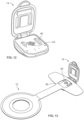
- the wearable subsystem 14 according to an embodiment is shown in FIGS. 12 and 13 .
- the wearable subsystem 14 may comprise a hinged case, an imbedded circuit board, a battery, a motor, and alignment members 40 that correspond to alignment members 36 of the sensing accessory 12.
- the circuit board may include conductive members 24 configured to contact terminal ends of sensing traces of the sensing accessory 12, such as the connecting points 34 ( FIG. 7 ).
- the conductive members 24 comprising a plurality of raised conductive pads may be arranged generally in a center area of a bottom housing of the wearable subsystem 14.
- the alignment members 40 may comprise two raised members, each of which may be arranged on each side of the conductive members 24 as shown in FIG. 12 .
- the alignment members 36 of the sensing accessory 12 may be defined by two openings in the connector region 30, which may be configured to receive the raised alignment members 40 of the wearable subsystem 14.
- the alignment members 36, 40 may be configured to facilitate correct attachment of the wearable subsystem 14 to the sensing accessory 12 to ensure electrical connection therebetween.
- a user may form a connection between the sensing accessory 12 and the wearable subsystem 14 by aligning the corresponding alignment members 36, 40 as shown in FIG. 13 and closing the wearable subsystem 14.
- the circuit board of the wearable subsystem 14 may include a processor and other components to analyze signals received from the sensing accessory 12, communicate with external devices, such as a mobile device and a charging dock 16, and alert a user vis sound, vibration, LEDs, etc. to notify a system status.
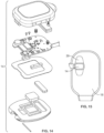
- FIG. 14 is an exploded view of a wearable subsystem 14 according to an embodiment.
- the wearable subsystem 14 may be secured to an ostomy pouch 18 or user via adhesive pads 39 attached to the sensing accessory 12 as shown in FIG. 15 .
- the adhesive pads 39 may be covered with release liners, which may be removed before use.
- FIGS. 16 and 17 show a wearable subsystem 114 according to another embodiment.
- the wearable subsystem 114 may be configured similar to the wearable subsystem 14, generally comprising a hinged case, an imbedded circuit board, a battery, a motor, and an alignment member 140 that correspond to an alignment member 136 of the sensing accessory 112.
- the circuit board may include conductive members 124 configured to contact the connecting points 134 of the sensing accessory 112.
- the wearable subsystem alignment member 140 may comprise a center raised key member 141 and a peripheral raised member 143.
- the center raised key member 141 may be arranged generally in the center of a bottom housing of the wearable subsystem 114, while the peripheral raised member 143 may be arranged proximate a hinge 145.
- the alignment member 136 of the sensing accessory 112 may be defined by openings in the connector region 130, which may be configured to receive the raised alignment member 140 of the wearable subsystem 14.
- the alignment member 136 may include a center key opening 138 configured to receive the center raised key member 141 and a peripheral opening 139 configured to receive the peripheral raised member 143.
- the alignment members 136, 140 may be configured to facilitate correct attachment of the wearable subsystem 114 to the sensing accessory 112 to ensure electrical connection therebetween.
- the wearable subsystem 114 may be attached to an ostomy pouch or user via an adhesive pad 102 as shown in FIGS. 18-21 .
- the wearable subsystem 14, 114 may poll resistance measurements from conductive traces to collect resistance data, which may be processed through an algorithm for determining an ostomy effluent leakage event.
- the algorithm may consider resistance measurements and other factors, such as resistance measurements from neighboring conductive traces, a change in resistance from recent prior resistance measurements, historical data from prior uses, etc.
- the wearable subsystem 14, 114 may alert a user via sound, vibration, light, etc. according the leakage event.
- An alert may be sent based on resistance measurements received from multiple sensors, patterns in measurements, user preference inputs, signals received from other components of the ostomy leakage detection system, such as a mobile application and/or charging dock.
- the wearable subsystem 14, 114 may be configured to communicate data to a mobile application.
- the data may be raw sensor data as received from the sensing accessory 12, 112 or processed data processed by the wearable subsystem 14, 114, which may include a summarized data and/or a leakage event information.
- the wearable subsystem 14, 114 may also be configured to communicate system conditions, such as the connectivity of the sensing accessory 12, 112, a faulty sensor, a state of battery, etc.
- the wearable subsystem 14, 114 may be powered by a battery or recharged by the charging dock 16.
- the wearable subsystem 14, 114 may include conductive pads on a charge circuit portion of the circuit board, which may be configured to contact pins on the charging dock 16.
- the charging dock 16 may comprise a medical grade power supply unit and a housing including charging pins 52 for electronically connecting to the wearable subsystem 14, 114.
- the housing may also include additional components, for example, a speaker and LEDs for sending alerts and feedback to a user, and a wireless communication module for communicating with the wearable subsystem 14, 114 and a mobile application.
- the charging dock 16 may be configured to recharge a rechargeable battery of the wearable subsystem 14, 114.
- an electrical connection may be formed between the charging pins 52 and conductive pads of the wearable subsystem 14, 114.
- a charging circuit of the wearable subsystem 14, 114 may be configured to ensure a safe recharge.
- the charging dock 16 may be configured to provide an additional means for alerting a user about leakage events.
- the user may have an option to receive leak alerts from the charging dock 16. This option may be most advantageous at night when other means of alerting may not be as effective for users during sleep. For example, a vibration alert from the wearable subsystem 14, 114 may not be effective to rouse a sleeping user.
- the user may also power down or disable sounds from a mobile phone at night. As such, the user may opt to receive alerts from the charging dock 16.
- the wearable subsystem 14, 114 may be configured to determines a leakage event and send a signal to the charging dock 16 via Bluetooth communication.
- the charging dock 15 may be configured to send an audible alert through a speaker and/ or a visual alert through LEDs when a leakage event signal is received. Certain aspects of the alert, such as volume and duration, may be configurable by the user.
- the mobile application may be configured to provide means for users to interact with the ostomy leakage detection system 10. For example, a user may set preferences for alerts and review historical data, such as analysis of leakage patterns and usage trends, by using the mobile application.
- the mobile application may also be configured to functions as a resource for connecting the user to support, such as training materials, experts at the manufacturer, and ostomy clinicians.
- the mobile application may be configured to communicate with the wearable subsystem 14, 114 and the charging dock 16 over Bluetooth.
- the mobile application may be configured to confirm these connections and alerts if a subsystem is unavailable.
- the mobile application may be configured to alert the user about leakage events and/or system issues through alert functions of a mobile phone, such as sound and vibration.
- the mobile application may be configured to relay data to a cloud server for storage and/or data analysis, for example prediction of leaks based on repeated wears, comparison to the leakage patterns of other users of the system, or other factors.
- a communication link between a cloud system and the mobile application may allow for additional features, such as product recommendations based on leakage patterns or other data, re-ordering of products in a convenient or automatic format, direct consultation with a clinician, storage of photographs of the stoma or peristomal skin for tracking alongside leakage patterns, etc.
- FIG. 25 A diagram of communication between subsystems of the ostomy leakage detection system 10 and communication between the ostomy leakage detection system 10 and a cloud system according to an embodiment is shown in FIG. 25 .
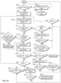
- FIG. 24 is a block diagram for a method of detecting an ostomy effluent leakage using the ostomy leakage detection system 10 according to an embodiment.
- the steps of the method of detecting an ostomy effluent leakage may be configured for accurate determination of leakage events and to minimize false detections.
- the method may include the step of providing a sensing accessory 12, 112 comprising a plurality of sensors, for example, 8 sensors, arranged adjacent an adhesive or embedded in the adhesive. Each of the plurality of sensors may be formed from a pair of conductive traces configured to measure resistance of the adhesive.
- the method may also include the step of determining whether the sensing accessory 12, 112 is electrically connected to the wearable subsystem 14, 114.
- the wearable subsystem 14, 114 may send a signal to the sensing accessory 12, 112 requesting a return signal. If no signal is returned, the wearable subsystem 14, 114 may determine that the sensing accessory 12, 112 is not connected and increase a disconnect timer in the step of "Increment disconnect timer" 402.
- the wearable subsystem 14, 114 may also send the disconnect timer data to an external device, such as user's phone, when the sensing accessory 12, 112 is not connected to the wearable device 14, 114 in the step of "Push time to phone" 404.
- the sensor may be flagged in the step of "Increment sensor flag" 412.
- the ring buffer may be configured to hold a current resistance measurement and four previous resistance measurements for each sensor, wherein the resistance measurements may be used to calculate a median filter value (a median of the five resistance measurements) in the step of "Median filter” 426.
- the ring buffer may be continuously pushed through the median filter which is a median of the last five resistance measurements.
- the predetermined range of acceptable resistance values may be set at less than a threshold resistance value of 1 M ⁇ . In the step of "Is resistance ⁇ 1000 k ⁇ ?" 428, whether a median filter value of a sensor is less than the threshold value may be determined. If the median filter value of the sensor is less than the threshold value, the status of that sensor is checked in the step of "Is sensor in leak state?" 430.
- a leak count of the sensor may be incremented in the step of "Increment Leak Count" 432.
Landscapes
- Health & Medical Sciences (AREA)
- General Physics & Mathematics (AREA)
- Physics & Mathematics (AREA)
- Life Sciences & Earth Sciences (AREA)
- General Health & Medical Sciences (AREA)
- Biomedical Technology (AREA)
- Heart & Thoracic Surgery (AREA)
- Vascular Medicine (AREA)
- Orthopedic Medicine & Surgery (AREA)
- Animal Behavior & Ethology (AREA)
- Engineering & Computer Science (AREA)
- Public Health (AREA)
- Veterinary Medicine (AREA)
- Nursing (AREA)
- Epidemiology (AREA)
- Orthopedics, Nursing, And Contraception (AREA)
- Measuring And Recording Apparatus For Diagnosis (AREA)
Applications Claiming Priority (4)
| Application Number | Priority Date | Filing Date | Title |
|---|---|---|---|
| US202063030713P | 2020-05-27 | 2020-05-27 | |
| US202163139034P | 2021-01-19 | 2021-01-19 | |
| EP21739822.1A EP4158298B1 (de) | 2020-05-27 | 2021-05-20 | Stomaleckerkennungssystem |
| PCT/US2021/033417 WO2021242603A1 (en) | 2020-05-27 | 2021-05-20 | Ostomy leakage detection system |
Related Parent Applications (2)
| Application Number | Title | Priority Date | Filing Date |
|---|---|---|---|
| EP21739822.1A Division-Into EP4158298B1 (de) | 2020-05-27 | 2021-05-20 | Stomaleckerkennungssystem |
| EP21739822.1A Division EP4158298B1 (de) | 2020-05-27 | 2021-05-20 | Stomaleckerkennungssystem |
Publications (3)
| Publication Number | Publication Date |
|---|---|
| EP4579206A2 true EP4579206A2 (de) | 2025-07-02 |
| EP4579206A3 EP4579206A3 (de) | 2025-07-16 |
| EP4579206B1 EP4579206B1 (de) | 2026-04-22 |
Family
ID=76845303
Family Applications (2)
| Application Number | Title | Priority Date | Filing Date |
|---|---|---|---|
| EP25172023.1A Active EP4579206B1 (de) | 2020-05-27 | 2021-05-20 | Stomaleckerkennungssystem |
| EP21739822.1A Active EP4158298B1 (de) | 2020-05-27 | 2021-05-20 | Stomaleckerkennungssystem |
Family Applications After (1)
| Application Number | Title | Priority Date | Filing Date |
|---|---|---|---|
| EP21739822.1A Active EP4158298B1 (de) | 2020-05-27 | 2021-05-20 | Stomaleckerkennungssystem |
Country Status (9)
| Country | Link |
|---|---|
| US (1) | US12292355B2 (de) |
| EP (2) | EP4579206B1 (de) |
| AU (1) | AU2021281459B2 (de) |
| CA (1) | CA3175645A1 (de) |
| DK (1) | DK4158298T3 (de) |
| HU (1) | HUE072705T2 (de) |
| LT (1) | LT4158298T (de) |
| PT (1) | PT4158298T (de) |
| WO (1) | WO2021242603A1 (de) |
Families Citing this family (8)
| Publication number | Priority date | Publication date | Assignee | Title |
|---|---|---|---|---|
| DK4158298T3 (da) | 2020-05-27 | 2025-08-18 | Hollister Inc | System til registrering af stomilækage |
| CA3245122A1 (en) * | 2022-03-21 | 2023-09-28 | Hollister Incorporated | Charging docking station for stoma leak detection system |
| USD1051039S1 (en) | 2022-09-19 | 2024-11-12 | Hollister Incorporated | Charging dock |
| WO2025006274A1 (en) * | 2023-06-28 | 2025-01-02 | Hollister Incorporated | Method and graphical user interface for determining and displaying ostomy leakage information |
| WO2025006071A1 (en) * | 2023-06-28 | 2025-01-02 | Hollister Incorporated | Sensing accessory for ostomy leakage detection system |
| WO2025006098A1 (en) * | 2023-06-28 | 2025-01-02 | Hollister Incorporated | Wearable device for ostomy leakage detection system |
| WO2025006828A1 (en) * | 2023-06-28 | 2025-01-02 | Hollister Incorporated | Release liners for ostomy leakage sensing accessory |
| CN120983204A (zh) * | 2025-10-22 | 2025-11-21 | 义乌市中心医院(义乌市中心医院医共体) | 一种智能化造口底盘智能监控系统 |
Family Cites Families (118)
| Publication number | Priority date | Publication date | Assignee | Title |
|---|---|---|---|---|
| US2327514A (en) * | 1942-08-21 | 1943-08-24 | Ivy D Fenwick | Colostomy protector |
| US2542233A (en) * | 1949-03-03 | 1951-02-20 | Harry F Carroll | Colostomy closure or guard |
| US2544579A (en) * | 1949-06-20 | 1951-03-06 | Frank J Ardner | Colostomy protector |
| US5672163A (en) * | 1996-04-26 | 1997-09-30 | Bristol-Myers Squibb Company | Ostomy pouch with intervening membrane and superabsorbent |
| DE69825585T2 (de) * | 1997-04-08 | 2005-08-11 | Coloplast A/S | Stoma-vorrichtung |
| FR2785526B1 (fr) * | 1998-11-06 | 2001-03-30 | Plasto Sa | Dispositif de securite pour colostomie |
| DK175870B1 (da) * | 2001-09-05 | 2005-05-02 | Coloplast As | Stomiindretning |
| DK175356B1 (da) * | 2002-02-28 | 2004-09-06 | Coloplast As | Stomiindretning |
| SE0201907D0 (sv) * | 2002-06-19 | 2002-06-19 | Atos Medical Ab | Plaster for tracheostoma valves |
| US7625362B2 (en) * | 2003-09-16 | 2009-12-01 | Boehringer Technologies, L.P. | Apparatus and method for suction-assisted wound healing |
| US7166091B1 (en) * | 2003-12-11 | 2007-01-23 | Keith Zeltner | Recreational belt for supporting and housing an ostomy appliance |
| CA2467413A1 (en) * | 2004-05-18 | 2005-11-18 | Wayne Conrad | Improved ostomy appliance |
| EP2412306B1 (de) * | 2005-03-09 | 2017-08-30 | DELTA, Dansk Elektronik, Lys & Akustik | Dreidimensionale Klebevorrichtung mit darin eingebettetem mikroelektronischem System |
| US7326190B2 (en) * | 2005-05-25 | 2008-02-05 | Hollister Incorporated | Ostomy pouch and high performance deodorizing gas filter assembly therefor |
| US7641612B1 (en) * | 2006-01-17 | 2010-01-05 | Mccall Kenneth Shawn | Blood loss detection for hemodialysis system |
| BRPI0707961A2 (pt) * | 2006-02-28 | 2011-05-10 | Coloplast As | mÉtodo para detectar o desprendimento de um curativo, curativo apropriado para aplicar o mÉtodo, conjunto sensor e blindagem para reduzir o acoplamento capacitivo a partir das vizinhanÇas ambientais para os eletrodos do curativo |
| US11389171B2 (en) * | 2006-11-21 | 2022-07-19 | David S. Goldsmith | Integrated system for the infixion and retrieval of implants |
| US10646370B2 (en) * | 2008-04-01 | 2020-05-12 | Donaldson Company, Inc. | Enclosure ventilation filter and assembly method |
| US8979811B2 (en) * | 2008-04-01 | 2015-03-17 | Donaldson Company, Inc. | Enclosure ventilation filter and assembly method |
| US7981099B2 (en) * | 2008-07-10 | 2011-07-19 | Hollister Incorporated | Deodorizing gas filter assembly for a body waste collection pouch, and method of making |
| BR112012000377B1 (pt) * | 2009-07-07 | 2019-10-08 | Coloplast A/S | Dispositivo de ostomia com um indicador de vazamento |
| CN102470042B (zh) * | 2009-07-07 | 2015-03-18 | 科洛普拉斯特公司 | 一种带有泄漏指示器的造口术器具 |
| EP2754426B1 (de) * | 2010-06-04 | 2015-08-19 | Coloplast A/S | Künstlicher Darmausgang mit einer Filterkonstruktion |
| DE102010024654A1 (de) * | 2010-06-22 | 2011-12-22 | Fresenius Medical Care Deutschland Gmbh | Vorrichtung zum Detektieren von Feuchtigkeit zur Verwendung mit einer Vorrichtung zur Überwachung eines Zugangs zu einem Patienten, insbesondere zur Überwachung des Gefäßzugangs bei einer extrakorporalen Blutbehandlung |
| US8684982B2 (en) * | 2010-10-29 | 2014-04-01 | Convatec Technologies Inc. | Controlled evacuation ostomy appliance |
| JP6783519B2 (ja) | 2012-11-20 | 2020-11-11 | コンバテック・テクノロジーズ・インコーポレイテッドConvatec Technologies Inc | ワンピースオストミーパウチの改良 |
| WO2014152863A2 (en) * | 2013-03-14 | 2014-09-25 | Hollister Corporation | Three-dimensional adhesive patch |
| GB201313721D0 (en) * | 2013-07-31 | 2013-09-11 | Univ Ulster | Leak detection sensor for a stoma pouch and a process for making same |
| US10531977B2 (en) | 2014-04-17 | 2020-01-14 | Coloplast A/S | Thermoresponsive skin barrier appliances |
| EP3034054B1 (de) * | 2014-12-16 | 2021-01-20 | Absorbest AB | Wundauflage mit einem Sensor und Verfahren zur Herstellung davon |
| US9928341B2 (en) * | 2015-11-12 | 2018-03-27 | Vivante Health, Inc. | Systems and methods for providing comprehensive care for stoma patients |
| WO2017088153A1 (zh) | 2015-11-26 | 2017-06-01 | 深圳市泽智知识产权有限公司 | 用于医疗器械的漏液检测装置 |
| GB201609954D0 (en) * | 2016-06-07 | 2016-07-20 | Monty Stephanie | A dressing |
| CN109561980B (zh) * | 2016-08-12 | 2021-09-21 | 科洛普拉斯特公司 | 造口术器具 |
| EP3409248B1 (de) * | 2017-06-01 | 2019-11-06 | Absorbest AB | Wundauflage |
| WO2019094635A1 (en) * | 2017-11-09 | 2019-05-16 | 11 Health and Technologies Inc. | Ostomy monitoring system and method |
| WO2019120441A1 (en) | 2017-12-22 | 2019-06-27 | Coloplast A/S | Sensor assembly part and a base plate for an ostomy appliance and a method for manufacturing a sensor assembly part and a base plate |
| AU2018386865B2 (en) * | 2017-12-22 | 2024-03-14 | Coloplast A/S | Ostomy system and monitor device with angular leakage detection |
| WO2019120452A1 (en) | 2017-12-22 | 2019-06-27 | Coloplast A/S | Coupling part with a hinge for an ostomy base plate and sensor assembly part |
| WO2019120458A1 (en) | 2017-12-22 | 2019-06-27 | Coloplast A/S | Base plate for an ostomy appliance, a monitor device and a system for an ostomy appliance |
| CN111432756B (zh) | 2017-12-22 | 2022-07-29 | 科洛普拉斯特公司 | 具有泄漏传感器的造口术系统的底板和传感器组件部 |
| EP3727247B1 (de) * | 2017-12-22 | 2022-04-20 | Coloplast A/S | Werkzeuge und verfahren zur platzierung einer stomavorrichtung an einem benutzer |
| EP3729456B1 (de) * | 2017-12-22 | 2021-12-01 | Coloplast A/S | Überwachungsvorrichtung eines stomasystems und zugehöriges verfahren zum betrieb einer überwachungsvorrichtung |
| US11612508B2 (en) * | 2017-12-22 | 2023-03-28 | Coloplast A/S | Sensor assembly part for a medical appliance and a method for manufacturing a sensor assembly part |
| US12064369B2 (en) * | 2017-12-22 | 2024-08-20 | Coloplast A/S | Processing schemes for an ostomy system, monitor device for an ostomy appliance and related methods |
| US10849781B2 (en) * | 2017-12-22 | 2020-12-01 | Coloplast A/S | Base plate for an ostomy appliance |
| EP3998051B1 (de) * | 2017-12-22 | 2025-05-07 | Coloplast A/S | Zubehörvorrichtungen eines stomasystems und zugehörige verfahren zur kommunikation des betriebszustands |
| US10500084B2 (en) * | 2017-12-22 | 2019-12-10 | Coloplast A/S | Accessory devices of an ostomy system, and related methods for communicating leakage state |
| EP4595934A3 (de) * | 2017-12-22 | 2025-11-05 | Coloplast A/S | Überwachungsvorrichtung für ein stomasystem mit einem verbinder zur verbindung mit einer grundplatte und einer zubehörvorrichtung |
| US11654043B2 (en) * | 2017-12-22 | 2023-05-23 | Coloplast A/S | Sensor assembly part and a base plate for a medical appliance and a method for manufacturing a base plate or a sensor assembly part |
| EP3727220B1 (de) * | 2017-12-22 | 2023-07-12 | Coloplast A/S | Stomasystem, überwachungsvorrichtung und verfahren zur überwachung eines stomas |
| EP3727223B1 (de) * | 2017-12-22 | 2024-02-07 | Coloplast A/S | Stomavorrichtung mit elektrodenmultiplexierung und zugehörige verfahren |
| EP3727230B1 (de) | 2017-12-22 | 2025-03-12 | Coloplast A/S | Thermoreaktive hautbarrierevorrichtungen |
| JP7282781B2 (ja) * | 2017-12-22 | 2023-05-29 | コロプラスト アクティーゼルスカブ | 角度範囲漏出検出機能を備えるオストミー装具 |
| US10799385B2 (en) * | 2017-12-22 | 2020-10-13 | Coloplast A/S | Ostomy appliance with layered base plate |
| EP3727241A1 (de) * | 2017-12-22 | 2020-10-28 | Coloplast A/S | Datensammelschemata für eine stomavorrichtung und zugehörige verfahren |
| US11819443B2 (en) * | 2017-12-22 | 2023-11-21 | Coloplast A/S | Moisture detecting base plate for a medical appliance and a system for determining moisture propagation in a base plate and/or a sensor assembly part |
| LT3727228T (lt) * | 2017-12-22 | 2022-08-10 | Coloplast A/S | Pagrindinė plokštė ir jutiklių konstrukcijos dalis ostomijos prietaisui ir būdas pagrindinei plokštei ir jutiklių konstrukcijos daliai gaminti |
| EP3727227B1 (de) * | 2017-12-22 | 2023-06-07 | Coloplast A/S | Grundplatte für eine stomavorrichtung und sensorbauteil für eine grundplatte und verfahren zur herstellung einer grundplatte und eines sensorbauteil |
| EP3727224B1 (de) * | 2017-12-22 | 2022-11-02 | Coloplast A/S | Grundplatte und sensorbauteil eines stomasystems mit feuchtigkeitssensor |
| BR112020011316B1 (pt) * | 2017-12-22 | 2023-12-05 | Coloplast A/S | Placa-base para um aparelho de ostomia, e, método para fabricar uma placa-base de um aparelho de ostomia |
| EP4640191A3 (de) | 2017-12-22 | 2026-01-07 | Coloplast A/S | Datenübertragungsschemata für ein stomasystem, überwachungsvorrichtung für eine stomavorrichtung und zugehörige verfahren |
| AU2018386864A1 (en) * | 2017-12-22 | 2020-06-25 | Coloplast A/S | System including a skin-engageable element of an ostomy appliance |
| US11628084B2 (en) * | 2017-12-22 | 2023-04-18 | Coloplast A/S | Sensor assembly part and a base plate for a medical appliance and a device for connecting to a base plate or a sensor assembly part |
| US11291577B2 (en) * | 2018-02-02 | 2022-04-05 | 11 Health And Technologies Limited | Ostomy patient care system and method |
| US11918507B2 (en) * | 2018-02-05 | 2024-03-05 | Coloplast A/S | Medical system and monitor device with sensor unit |
| EP4631480A3 (de) | 2018-02-20 | 2025-12-10 | Coloplast A/S | Zubehörgeräte für ein stomasystem und zugehörige verfahren zum wechseln einer stomavorrichtung auf der grundlage eines zukünftigen betriebszustands |
| EP3755280B1 (de) | 2018-02-20 | 2024-07-31 | Coloplast A/S | Zubehörvorrichtungen eines stomasystems, stomasysteme und zugehörige verfahren für den zukünftigen betriebszustand |
| EP3755283B1 (de) * | 2018-02-20 | 2024-05-01 | Coloplast A/S | Sensorbaugruppenteil und eine grundplatte und ein stomabeutel für eine stomavorrichtung und vorrichtung zum anschluss an eine grundplatte und/oder ein sensorbaugruppenteil |
| WO2019161861A1 (en) | 2018-02-20 | 2019-08-29 | Coloplast A/S | Sensor assembly part and a base plate for an ostomy appliance and a device for connecting to a base plate and/or a sensor assembly part |
| US20200395120A1 (en) * | 2018-02-20 | 2020-12-17 | Coloplast A/S | Methods for medical appliance change and related accessory devices of a medical system |
| EP4079266B1 (de) | 2018-03-15 | 2024-06-05 | Coloplast A/S | Verfahren zur verwaltung der resttragezeit einer stomavorrichtung und zugehörige zubehörgeräte |
| US20210007663A1 (en) * | 2018-03-15 | 2021-01-14 | Coloplast A/S | Medical system, server device, and accessory device for medical appliance base plate monitoring based on user types |
| WO2019174698A1 (en) | 2018-03-15 | 2019-09-19 | Coloplast A/S | Methods of configuring ostomy notifications and related accessory devices |
| US20210000414A1 (en) * | 2018-03-15 | 2021-01-07 | Coloplast A/S | Medical system, server device, and accessory device for medical appliance base plate monitoring |
| WO2019174692A1 (en) | 2018-03-15 | 2019-09-19 | Coloplast A/S | Apparatus and methods for determining ostomy appliance wear time based on location data |
| WO2019174696A1 (en) | 2018-03-15 | 2019-09-19 | Coloplast A/S | Apparatus and methods for determining ostomy appliance wear time based on sensor data |
| AU2019233298B2 (en) | 2018-03-15 | 2024-08-15 | Coloplast A/S | Ostomy system, accessory device, and related methods |
| EP4470512A3 (de) | 2018-03-15 | 2025-01-22 | Coloplast A/S | Verfahren für zukünftigen betriebszustand und entsprechendes zubehör eines stomasystems und stomasysteme |
| US11998474B2 (en) * | 2018-03-15 | 2024-06-04 | Coloplast A/S | Apparatus and methods for navigating ostomy appliance user to changing room |
| EP3806785B1 (de) | 2018-06-15 | 2026-04-08 | Coloplast A/S | Wundverband mit elektrodenmultiplexing und zugehörige verfahren |
| WO2019238181A1 (en) | 2018-06-15 | 2019-12-19 | Coloplast A/S | Moisture sensing wound dressing |
| EP3806792B1 (de) | 2018-06-15 | 2024-11-06 | Coloplast A/S | Feuchtigkeitsbeurteilungssystem und verfahren zur wundversorgung |
| US12097040B2 (en) | 2018-06-15 | 2024-09-24 | Coloplast A/S | Wound dressing system and method with data collection based on environmental factor of geographic location |
| US20200000624A1 (en) * | 2018-06-28 | 2020-01-02 | Jennifer Gibbons | Ostomy Leakage Alert System |
| JP7460603B2 (ja) | 2018-08-15 | 2024-04-02 | コロプラスト アクティーゼルスカブ | オストミーシステムの付属デバイス及び問題識別の関連方法 |
| WO2020076607A1 (en) * | 2018-10-09 | 2020-04-16 | Hollister Incorporated | Ostomy appliance having conductive ink circuit for leakage detection |
| CN113473948B (zh) | 2018-12-13 | 2026-03-17 | 康沃特克科技公司 | 造口术监测系统和方法 |
| US11529253B2 (en) * | 2019-01-31 | 2022-12-20 | Coloplast A/S | Base plate for an ostomy appliance and a sensor assembly part for a base plate and a method for manufacturing a base plate and sensor assembly part |
| US12232998B2 (en) | 2019-01-31 | 2025-02-25 | Coloplast A/S | Application of a stomal sensor patch |
| US11517469B2 (en) * | 2019-01-31 | 2022-12-06 | Coloplast A/S | Base plate and sensor assembly part of an ostomy system having a moisture sensor |
| EP4674392A3 (de) | 2019-01-31 | 2026-04-01 | Coloplast A/S | Sensoreinrichtung für eine ostomievorrichtung |
| US11612512B2 (en) * | 2019-01-31 | 2023-03-28 | Coloplast A/S | Moisture detecting base plate for an ostomy appliance and a system for determining moisture propagation in a base plate and/or a sensor assembly part |
| US12558250B2 (en) * | 2019-01-31 | 2026-02-24 | Coloplast A/S | Base plate and a sensor assembly part for an ostomy appliance |
| KR102807748B1 (ko) | 2019-01-31 | 2025-05-14 | 컬러플라스트 에이/에스 | 스토마용 센서 패치 |
| EP3927291B1 (de) | 2019-02-21 | 2025-07-16 | Coloplast A/S | Überwachungsvorrichtung für stoma |
| EP3930642B1 (de) | 2019-02-28 | 2023-10-25 | Coloplast A/S | Sensorpflaster zur befestigung an einer grundplatte |
| US20220192860A1 (en) | 2019-04-26 | 2022-06-23 | Coloplast A/S | Sensor Patch for Attachment to a Base Plate |
| BR112021020978A2 (pt) | 2019-04-26 | 2021-12-14 | Coloplast As | Método, sistema de ostomia, e, dispositivo de monitor |
| US12310878B2 (en) | 2019-04-26 | 2025-05-27 | Coloplast A/S | Alignment aid for aligning a sensor patch to a base plate |
| WO2020259775A1 (en) | 2019-06-24 | 2020-12-30 | Coloplast A/S | A stomal sensor patch |
| US12485033B2 (en) * | 2019-06-26 | 2025-12-02 | Coloplast A/S | Device for connecting a base plate and/or a sensor patch for a medical device |
| EP3989888B1 (de) * | 2019-06-26 | 2023-10-25 | Coloplast A/S | Eine stomavorrichtung |
| WO2020259785A1 (en) * | 2019-06-26 | 2020-12-30 | Coloplast A/S | Ostomy system and electrode assembly with angular leakage detection |
| EP4675296A3 (de) | 2019-09-25 | 2026-03-18 | Coloplast A/S | Geräteschnittstelle, system und verfahren zur flüssigkeitseintrittserkennung in die geräteschnittstelle |
| WO2021063466A1 (en) | 2019-10-04 | 2021-04-08 | Coloplast A/S | A medical device system |
| US20210100533A1 (en) * | 2019-10-08 | 2021-04-08 | 11 Health and Technologies Inc. | Systems and methods for analysis of urine and fecal matter |
| CN115003261A (zh) * | 2020-01-20 | 2022-09-02 | 科洛普拉斯特公司 | 用于造口术器具的底板 |
| GB202002407D0 (en) | 2020-02-20 | 2020-04-08 | Eakin R&D Ltd | A collecting device |
| GB202002396D0 (en) | 2020-02-20 | 2020-04-08 | Eakin R&D Ltd | A collecting device |
| US20240009019A1 (en) | 2020-03-20 | 2024-01-11 | Coloplast A/S | Monitor device with human-readable identifier |
| WO2021209104A1 (en) | 2020-04-14 | 2021-10-21 | Coloplast A/S | Personal care system with monitor device and a plurality of accessory devices, and related methods |
| DK4158298T3 (da) | 2020-05-27 | 2025-08-18 | Hollister Inc | System til registrering af stomilækage |
| GB202008262D0 (en) | 2020-06-02 | 2020-07-15 | Convatec Ltd | Ostomy pouch |
| EP4545056A3 (de) | 2020-09-28 | 2025-07-16 | Coloplast A/S | Medizinische vorrichtung |
| CN116348962A (zh) | 2020-10-14 | 2023-06-27 | 科洛普拉斯特公司 | 用于个人护理系统的具有传感器分类器的监测设备和相关方法 |
| JP2023545504A (ja) | 2020-10-15 | 2023-10-30 | コンバテック・テクノロジーズ・インコーポレイテッド | オストミーシステムおよび方法 |
| WO2022207049A1 (en) | 2021-03-29 | 2022-10-06 | Coloplast A/S | Liquid sensing in ostomy appliance |
-
2021
- 2021-05-20 DK DK21739822.1T patent/DK4158298T3/da active
- 2021-05-20 EP EP25172023.1A patent/EP4579206B1/de active Active
- 2021-05-20 US US17/917,164 patent/US12292355B2/en active Active
- 2021-05-20 LT LTEPPCT/US2021/033417T patent/LT4158298T/lt unknown
- 2021-05-20 AU AU2021281459A patent/AU2021281459B2/en active Active
- 2021-05-20 PT PT217398221T patent/PT4158298T/pt unknown
- 2021-05-20 HU HUE21739822A patent/HUE072705T2/hu unknown
- 2021-05-20 EP EP21739822.1A patent/EP4158298B1/de active Active
- 2021-05-20 CA CA3175645A patent/CA3175645A1/en active Pending
- 2021-05-20 WO PCT/US2021/033417 patent/WO2021242603A1/en not_active Ceased
Also Published As
| Publication number | Publication date |
|---|---|
| US20230160771A1 (en) | 2023-05-25 |
| LT4158298T (lt) | 2025-08-11 |
| AU2021281459A1 (en) | 2022-11-10 |
| CA3175645A1 (en) | 2021-12-02 |
| PT4158298T (pt) | 2025-08-12 |
| EP4158298B1 (de) | 2025-07-09 |
| EP4158298A1 (de) | 2023-04-05 |
| DK4158298T3 (da) | 2025-08-18 |
| WO2021242603A1 (en) | 2021-12-02 |
| EP4579206A3 (de) | 2025-07-16 |
| US12292355B2 (en) | 2025-05-06 |
| EP4579206B1 (de) | 2026-04-22 |
| HUE072705T2 (hu) | 2025-12-28 |
| AU2021281459B2 (en) | 2026-03-05 |
Similar Documents
| Publication | Publication Date | Title |
|---|---|---|
| AU2021281459B2 (en) | Ostomy leakage detection system | |
| US11896512B2 (en) | Method of detecting leakage in medical devices | |
| US11737907B2 (en) | Moisture detecting base plate for an ostomy appliance and a system for determining moisture propagation in a base plate and/or a sensor assembly part | |
| US20240041635A1 (en) | Moisture detecting base plate for an ostomy appliance and a system for determining moisture propagation in a base plate and/or a sensor assembly part | |
| JP7460603B2 (ja) | オストミーシステムの付属デバイス及び問題識別の関連方法 | |
| US11517469B2 (en) | Base plate and sensor assembly part of an ostomy system having a moisture sensor | |
| EP3727224B1 (de) | Grundplatte und sensorbauteil eines stomasystems mit feuchtigkeitssensor | |
| JP7372919B2 (ja) | 動作状態を通信するオストミーシステムの付属デバイス及び関連方法 | |
| EP3764957B1 (de) | Stomasystem, zubehör und entsprechende verfahren | |
| JP7293230B2 (ja) | 漏出状態を通信するオストミーシステムの付属デバイス及び関連方法 | |
| US11717433B2 (en) | Medical appliance with angular leakage detection | |
| US12369853B2 (en) | Ostomy system for predicting a site of leakage |
Legal Events
| Date | Code | Title | Description |
|---|---|---|---|
| PUAI | Public reference made under article 153(3) epc to a published international application that has entered the european phase |
Free format text: ORIGINAL CODE: 0009012 |
|
| STAA | Information on the status of an ep patent application or granted ep patent |
Free format text: STATUS: THE APPLICATION HAS BEEN PUBLISHED |
|
| REG | Reference to a national code |
Ref country code: DE Free format text: PREVIOUS MAIN CLASS: G01M0003160000 Ref country code: DE Ref legal event code: R079 Ref document number: 602021052928 Country of ref document: DE Free format text: PREVIOUS MAIN CLASS: G01M0003160000 Ipc: G01M0003180000 |
|
| PUAL | Search report despatched |
Free format text: ORIGINAL CODE: 0009013 |
|
| AC | Divisional application: reference to earlier application |
Ref document number: 4158298 Country of ref document: EP Kind code of ref document: P |
|
| AK | Designated contracting states |
Kind code of ref document: A2 Designated state(s): AL AT BE BG CH CY CZ DE DK EE ES FI FR GB GR HR HU IE IS IT LI LT LU LV MC MK MT NL NO PL PT RO RS SE SI SK SM TR |
|
| AK | Designated contracting states |
Kind code of ref document: A3 Designated state(s): AL AT BE BG CH CY CZ DE DK EE ES FI FR GB GR HR HU IE IS IT LI LT LU LV MC MK MT NL NO PL PT RO RS SE SI SK SM TR |
|
| RIC1 | Information provided on ipc code assigned before grant |
Ipc: G01M 3/18 20060101AFI20250606BHEP Ipc: A61F 5/445 20060101ALI20250606BHEP Ipc: G01M 3/16 20060101ALI20250606BHEP |
|
| STAA | Information on the status of an ep patent application or granted ep patent |
Free format text: STATUS: REQUEST FOR EXAMINATION WAS MADE |
|
| 17P | Request for examination filed |
Effective date: 20250724 |
|
| GRAP | Despatch of communication of intention to grant a patent |
Free format text: ORIGINAL CODE: EPIDOSNIGR1 |
|
| STAA | Information on the status of an ep patent application or granted ep patent |
Free format text: STATUS: GRANT OF PATENT IS INTENDED |
|
| GRAS | Grant fee paid |
Free format text: ORIGINAL CODE: EPIDOSNIGR3 |
|
| GRAA | (expected) grant |
Free format text: ORIGINAL CODE: 0009210 |
|
| STAA | Information on the status of an ep patent application or granted ep patent |
Free format text: STATUS: THE PATENT HAS BEEN GRANTED |
|
| INTG | Intention to grant announced |
Effective date: 20260219 |
|
| AC | Divisional application: reference to earlier application |
Ref document number: 4158298 Country of ref document: EP Kind code of ref document: P |
|
| AK | Designated contracting states |
Kind code of ref document: B1 Designated state(s): AL AT BE BG CH CY CZ DE DK EE ES FI FR GB GR HR HU IE IS IT LI LT LU LV MC MK MT NL NO PL PT RO RS SE SI SK SM TR |
|
| REG | Reference to a national code |
Ref country code: CH Ref legal event code: F10 Free format text: ST27 STATUS EVENT CODE: U-0-0-F10-F00 (AS PROVIDED BY THE NATIONAL OFFICE) Effective date: 20260422 |