EP4579167A1 - Heat exchanger, and refrigeration cycle device - Google Patents
Heat exchanger, and refrigeration cycle device Download PDFInfo
- Publication number
- EP4579167A1 EP4579167A1 EP22956403.4A EP22956403A EP4579167A1 EP 4579167 A1 EP4579167 A1 EP 4579167A1 EP 22956403 A EP22956403 A EP 22956403A EP 4579167 A1 EP4579167 A1 EP 4579167A1
- Authority
- EP
- European Patent Office
- Prior art keywords
- refrigerant
- heat exchanger
- tube
- end portion
- flat tubes
- Prior art date
- Legal status (The legal status is an assumption and is not a legal conclusion. Google has not performed a legal analysis and makes no representation as to the accuracy of the status listed.)
- Pending
Links
Images






Classifications
-
- F—MECHANICAL ENGINEERING; LIGHTING; HEATING; WEAPONS; BLASTING
- F25—REFRIGERATION OR COOLING; COMBINED HEATING AND REFRIGERATION SYSTEMS; HEAT PUMP SYSTEMS; MANUFACTURE OR STORAGE OF ICE; LIQUEFACTION SOLIDIFICATION OF GASES
- F25B—REFRIGERATION MACHINES, PLANTS OR SYSTEMS; COMBINED HEATING AND REFRIGERATION SYSTEMS; HEAT PUMP SYSTEMS
- F25B39/00—Evaporators; Condensers
- F25B39/04—Condensers
-
- F—MECHANICAL ENGINEERING; LIGHTING; HEATING; WEAPONS; BLASTING
- F24—HEATING; RANGES; VENTILATING
- F24F—AIR-CONDITIONING; AIR-HUMIDIFICATION; VENTILATION; USE OF AIR CURRENTS FOR SCREENING
- F24F1/00—Room units for air-conditioning, e.g. separate or self-contained units or units receiving primary air from a central station
- F24F1/06—Separate outdoor units, e.g. outdoor unit to be linked to a separate room comprising a compressor and a heat exchanger
- F24F1/14—Heat exchangers specially adapted for separate outdoor units
- F24F1/18—Heat exchangers specially adapted for separate outdoor units characterised by their shape
-
- F—MECHANICAL ENGINEERING; LIGHTING; HEATING; WEAPONS; BLASTING
- F25—REFRIGERATION OR COOLING; COMBINED HEATING AND REFRIGERATION SYSTEMS; HEAT PUMP SYSTEMS; MANUFACTURE OR STORAGE OF ICE; LIQUEFACTION SOLIDIFICATION OF GASES
- F25B—REFRIGERATION MACHINES, PLANTS OR SYSTEMS; COMBINED HEATING AND REFRIGERATION SYSTEMS; HEAT PUMP SYSTEMS
- F25B6/00—Compression machines, plants or systems, with several condenser circuits
- F25B6/04—Compression machines, plants or systems, with several condenser circuits arranged in series
-
- F—MECHANICAL ENGINEERING; LIGHTING; HEATING; WEAPONS; BLASTING
- F28—HEAT EXCHANGE IN GENERAL
- F28D—HEAT-EXCHANGE APPARATUS, NOT PROVIDED FOR IN ANOTHER SUBCLASS, IN WHICH THE HEAT-EXCHANGE MEDIA DO NOT COME INTO DIRECT CONTACT
- F28D1/00—Heat-exchange apparatus having stationary conduit assemblies for one heat-exchange medium only, the media being in contact with different sides of the conduit wall, in which the other heat-exchange medium is a large body of fluid, e.g. domestic or motor car radiators
- F28D1/02—Heat-exchange apparatus having stationary conduit assemblies for one heat-exchange medium only, the media being in contact with different sides of the conduit wall, in which the other heat-exchange medium is a large body of fluid, e.g. domestic or motor car radiators with heat-exchange conduits immersed in the body of fluid
- F28D1/04—Heat-exchange apparatus having stationary conduit assemblies for one heat-exchange medium only, the media being in contact with different sides of the conduit wall, in which the other heat-exchange medium is a large body of fluid, e.g. domestic or motor car radiators with heat-exchange conduits immersed in the body of fluid with tubular conduits
- F28D1/0408—Multi-circuit heat exchangers, e.g. integrating different heat exchange sections in the same unit or heat exchangers for more than two fluids
- F28D1/0426—Multi-circuit heat exchangers, e.g. integrating different heat exchange sections in the same unit or heat exchangers for more than two fluids with units having particular arrangement relative to the large body of fluid, e.g. with interleaved units or with adjacent heat exchange units in common air flow or with units extending at an angle to each other or with units arranged around a central element
- F28D1/0443—Combination of units extending one beside or one above the other
-
- F—MECHANICAL ENGINEERING; LIGHTING; HEATING; WEAPONS; BLASTING
- F28—HEAT EXCHANGE IN GENERAL
- F28D—HEAT-EXCHANGE APPARATUS, NOT PROVIDED FOR IN ANOTHER SUBCLASS, IN WHICH THE HEAT-EXCHANGE MEDIA DO NOT COME INTO DIRECT CONTACT
- F28D1/00—Heat-exchange apparatus having stationary conduit assemblies for one heat-exchange medium only, the media being in contact with different sides of the conduit wall, in which the other heat-exchange medium is a large body of fluid, e.g. domestic or motor car radiators
- F28D1/02—Heat-exchange apparatus having stationary conduit assemblies for one heat-exchange medium only, the media being in contact with different sides of the conduit wall, in which the other heat-exchange medium is a large body of fluid, e.g. domestic or motor car radiators with heat-exchange conduits immersed in the body of fluid
- F28D1/04—Heat-exchange apparatus having stationary conduit assemblies for one heat-exchange medium only, the media being in contact with different sides of the conduit wall, in which the other heat-exchange medium is a large body of fluid, e.g. domestic or motor car radiators with heat-exchange conduits immersed in the body of fluid with tubular conduits
- F28D1/053—Heat-exchange apparatus having stationary conduit assemblies for one heat-exchange medium only, the media being in contact with different sides of the conduit wall, in which the other heat-exchange medium is a large body of fluid, e.g. domestic or motor car radiators with heat-exchange conduits immersed in the body of fluid with tubular conduits the conduits being straight
- F28D1/05316—Assemblies of conduits connected to common headers, e.g. core type radiators
- F28D1/05341—Assemblies of conduits connected to common headers, e.g. core type radiators with multiple rows of conduits or with multi-channel conduits combined with a particular flow pattern, e.g. multi-row multi-stage radiators
-
- F—MECHANICAL ENGINEERING; LIGHTING; HEATING; WEAPONS; BLASTING
- F28—HEAT EXCHANGE IN GENERAL
- F28F—DETAILS OF HEAT-EXCHANGE AND HEAT-TRANSFER APPARATUS, OF GENERAL APPLICATION
- F28F9/00—Casings; Header boxes; Auxiliary supports for elements; Auxiliary members within casings
- F28F9/02—Header boxes; End plates
- F28F9/026—Header boxes; End plates with static flow control means, e.g. with means for uniformly distributing heat exchange media into conduits
- F28F9/027—Header boxes; End plates with static flow control means, e.g. with means for uniformly distributing heat exchange media into conduits in the form of distribution pipes
-
- F—MECHANICAL ENGINEERING; LIGHTING; HEATING; WEAPONS; BLASTING
- F28—HEAT EXCHANGE IN GENERAL
- F28F—DETAILS OF HEAT-EXCHANGE AND HEAT-TRANSFER APPARATUS, OF GENERAL APPLICATION
- F28F9/00—Casings; Header boxes; Auxiliary supports for elements; Auxiliary members within casings
- F28F9/02—Header boxes; End plates
- F28F9/026—Header boxes; End plates with static flow control means, e.g. with means for uniformly distributing heat exchange media into conduits
- F28F9/027—Header boxes; End plates with static flow control means, e.g. with means for uniformly distributing heat exchange media into conduits in the form of distribution pipes
- F28F9/0273—Header boxes; End plates with static flow control means, e.g. with means for uniformly distributing heat exchange media into conduits in the form of distribution pipes with multiple holes
-
- F—MECHANICAL ENGINEERING; LIGHTING; HEATING; WEAPONS; BLASTING
- F25—REFRIGERATION OR COOLING; COMBINED HEATING AND REFRIGERATION SYSTEMS; HEAT PUMP SYSTEMS; MANUFACTURE OR STORAGE OF ICE; LIQUEFACTION SOLIDIFICATION OF GASES
- F25B—REFRIGERATION MACHINES, PLANTS OR SYSTEMS; COMBINED HEATING AND REFRIGERATION SYSTEMS; HEAT PUMP SYSTEMS
- F25B2339/00—Details of evaporators; Details of condensers
- F25B2339/04—Details of condensers
- F25B2339/044—Condensers with an integrated receiver
- F25B2339/0446—Condensers with an integrated receiver characterised by the refrigerant tubes connecting the header of the condenser to the receiver; Inlet or outlet connections to receiver
-
- F—MECHANICAL ENGINEERING; LIGHTING; HEATING; WEAPONS; BLASTING
- F25—REFRIGERATION OR COOLING; COMBINED HEATING AND REFRIGERATION SYSTEMS; HEAT PUMP SYSTEMS; MANUFACTURE OR STORAGE OF ICE; LIQUEFACTION SOLIDIFICATION OF GASES
- F25B—REFRIGERATION MACHINES, PLANTS OR SYSTEMS; COMBINED HEATING AND REFRIGERATION SYSTEMS; HEAT PUMP SYSTEMS
- F25B2339/00—Details of evaporators; Details of condensers
- F25B2339/04—Details of condensers
- F25B2339/045—Condensers made by assembling a tube on a plate-like element or between plate-like elements
-
- F—MECHANICAL ENGINEERING; LIGHTING; HEATING; WEAPONS; BLASTING
- F25—REFRIGERATION OR COOLING; COMBINED HEATING AND REFRIGERATION SYSTEMS; HEAT PUMP SYSTEMS; MANUFACTURE OR STORAGE OF ICE; LIQUEFACTION SOLIDIFICATION OF GASES
- F25B—REFRIGERATION MACHINES, PLANTS OR SYSTEMS; COMBINED HEATING AND REFRIGERATION SYSTEMS; HEAT PUMP SYSTEMS
- F25B41/00—Fluid-circulation arrangements
- F25B41/40—Fluid line arrangements
- F25B41/42—Arrangements for diverging or converging flows, e.g. branch lines or junctions
-
- F—MECHANICAL ENGINEERING; LIGHTING; HEATING; WEAPONS; BLASTING
- F28—HEAT EXCHANGE IN GENERAL
- F28D—HEAT-EXCHANGE APPARATUS, NOT PROVIDED FOR IN ANOTHER SUBCLASS, IN WHICH THE HEAT-EXCHANGE MEDIA DO NOT COME INTO DIRECT CONTACT
- F28D21/00—Heat-exchange apparatus not covered by any of the groups F28D1/00 - F28D20/00
- F28D2021/0019—Other heat exchangers for particular applications; Heat exchange systems not otherwise provided for
- F28D2021/008—Other heat exchangers for particular applications; Heat exchange systems not otherwise provided for for vehicles
- F28D2021/0084—Condensers
Definitions
- some refrigeration cycle apparatus includes a plurality of groups of heat exchangers, with one or more heat exchangers defined as one group.
- Such a refrigeration cycle apparatus is referable to, for example, Patent Literature 1.
- the heat exchanger in each of the plurality of groups is an air heat exchanger and has an upper header tube, a lower header tube, heat transfer tubes, and fins.
- groups are connected in parallel to each other and a parallel refrigerant flow passage is thus formed through which refrigerant is caused to flow in parallel to respective groups.
- All the heat exchangers in the parallel refrigerant flow passage each have heat transfer tubes through which refrigerant is caused to flow from below to above.
- a refrigerant distributor structured with a single tube is provided on an outflow side of a heat exchanger that serves as an evaporator.
- the refrigerant distributor has the function of distributing refrigerant to a plurality of heat transfer tubes included in the heat exchanger.
- connection states between the plurality of heat exchangers are distinguished between a case in which the series refrigerant flow passage is formed and a case in which the parallel refrigerant flow passage is formed.
- the plurality of heat exchangers mounted on the outdoor unit each serve as a condenser and the plurality of heat exchangers form with each other the series refrigerant flow passage, a heat exchanger located upstream in a flow passage and a heat exchanger located downstream are different in a state of refrigerant that flows in.
- gas refrigerant which is in a single phase, flows.
- refrigerant in a two-phase gas-liquid state in which gas refrigerant and liquid refrigerant is mixed to each other flows because a portion of the gas refrigerant exchanges heat and thus condenses in the heat exchanger located upstream.
- the refrigerant distributor on an inflow side of the heat exchanger located downstream in this case, however, is a refrigerant distributor structured with a single tube. In the heat exchanger located downstream, refrigerant caused to flow in is thus not evenly distributed to the plurality of flat tubes included in the heat exchanger.
- the amounts of the distributed refrigerant vary at different locations of flat tubes.
- the heat exchange amount is insufficient around the flat tubes into which a large amount of refrigerant is distributed.
- the heat exchange amount is excessive around the flat tubes into which a small amount of refrigerant is distributed. Such an uneven distribution causes a problem in that efficiency of heat exchange is reduced.
- Fig. 1 is a refrigerant circuit diagram that illustrates a configuration of a refrigeration cycle apparatus 100 according to Embodiment 1.
- the refrigeration cycle apparatus 100 has an outdoor unit 101 and an indoor unit 201 and forms a refrigeration cycle such that the outdoor unit 101 and the indoor unit 201 are connected to each other by a refrigerant pipe 310.
- the refrigerant pipe 310 includes a plurality of refrigerant pipes 300 to 308. These refrigerant pipes 300 to 308 described herein may be collectively referred to as the refrigerant pipe 310.
- the outdoor unit 101 and the indoor unit 201 are connected to each other at connection ports P1 and P2.
- the connection port P1 and the connection port P2 are each included in the refrigerant pipe 310.
- a refrigerant circuit included in the refrigeration cycle apparatus 100 is filled with a refrigerant such as a fluorocarbon refrigerant and an HFO refrigerant.
- fluorocarbon refrigerant also include a refrigerant mixture in which HFC refrigerants described above are mixed with each other.
- a refrigerant mixture include a refrigerant mixture R410A in which R32 and R125 are mixed with each other, a refrigerant mixture R407C in which R32, R125, and R134a are mixed with each other, and a refrigerant mixture R404A in which R125, R143a, and R134a are mixed with each other.
- HFO refrigerant which stands for a hydrofluoroolefin refrigerant
- HFO-1234yf HFO-1234ze(E)
- HFO-1234ze(Z) HFO-1234ze(Z)
- the outdoor unit 101 has a compressor 1, a four-way valve 2, an outdoor heat exchanger 3, an outdoor heat exchanger 4, an expansion valve 5, an expansion valve 6, a solenoid valve 7, a solenoid valve 8, two outdoor air-sending devices 9, an accumulator 10, and the refrigerant pipes 300 to 306 through which these components are connected to each other.
- the compressor 1 is a fluid machine configured to compress sucked low-pressure refrigerant and discharge the refrigerant as high-pressure refrigerant.
- the compressor 1 is, for example, a rotary compressor or a scroll compressor.
- the compressor 1 may also be, for example, a compressor of which rotational frequency is constant or a compressor of which rotational frequency is controllable with an inverter mounted.
- connection port 3b located across inside from the opposite connection port 3a is connected to the expansion valve 5 through the refrigerant pipe 302.
- the refrigerant pipe 302 is branched from between the outdoor heat exchanger 3 and the expansion valve 5 to the refrigerant pipe 303.
- the refrigerant pipe 303 is connected to the solenoid valve 7.
- the outdoor heat exchanger 3 allows air that passes through and refrigerant that flows inside to exchange heat with each other.
- the outdoor air-sending devices 9 are, for example, centrifugal fans, such as sirocco fans and turbo fans, cross-flow fans, diagonal-flow fans, or propeller fans.
- the outdoor heat exchanger 3 corresponds to a second heat exchanger described in Embodiment 1.
- the solenoid valve 7 and the solenoid valve 8 are each configured to open and close a flow passage depending on whether voltage is applied.
- the solenoid valve 7 and the solenoid valve 8 are configured block and open respective flows of refrigerant and thus switch flow passages of refrigerant.
- the controller 11 is formed by a processor circuit.
- the processor circuit is formed by dedicated hardware or a processor. Examples of the dedicated hardware include an application specific integrated circuit, which is also referred to as an ASIC, and a field programmable gate array, which is also referred to as an FPGA.
- the processor executes a program stored in a memory.
- the controller 11 has unillustrated memory circuitry.
- the memory circuitry is formed by a memory.
- the expansion valve 23 is configured to serve as a pressure reducing valve or an expansion valve and reduce the pressure of refrigerant and thus expand the refrigerant.
- the expansion valve 23 is, for example, a pressure reducing device such as a linear electronic expansion valve of which opening degree is multi-stepwise or serially adjustable.
- the controller 11 exercises control such that the expansion valve 5 is in a fully closed state, the solenoid valve 7 is in an open state, the solenoid valve 8 is in a closed state, and the expansion valve 6 is in a fully open state.
- the compressor 1 sucks in refrigerant from the accumulator 10 and then compresses the refrigerant.
- the compressed refrigerant turns into gas refrigerant, is then discharged from the compressor 1, and flows into the outdoor heat exchanger 3 through the four-way valve 2.
- the outdoor heat exchanger 3 a portion of the gas refrigerant condenses and the gas refrigerant then turns into a two-phase gas-liquid state of gas refrigerant and liquid refrigerant.
- the refrigerant flows out from the four-way valve 2, passes through the refrigerant pipe 306, and flows into the accumulator 10.
- the refrigerant is then sucked from the accumulator 10 into the compressor 1 again and circulates in the refrigerant circuit. This operation establishes a refrigerant circuit that has a refrigerant flow passage through which the outdoor heat exchanger 3 and the outdoor heat exchanger 4 are connected in series to each other.
- the controller 11 exercises control such that the expansion valve 5 is in a fully closed state, the solenoid valve 7 is in an open state, the solenoid valve 8 is in a closed state, and the expansion valve 6 is in a fully open state.
- the compressor 1 sucks in refrigerant from the accumulator 10 and then compresses the refrigerant.
- the compressed refrigerant turns into gas refrigerant, is then discharged from the compressor 1, and flows out through the four-way valve 2 from the outdoor unit 101 into the indoor unit 201.
- the refrigerant flows out from the four-way valve 2, passes through the refrigerant pipe 306, and flows into the accumulator 10.
- the refrigerant is then sucked from the accumulator 10 into the compressor 1 again and circulates in the refrigerant circuit. This operation establishes a refrigerant circuit that has a refrigerant flow passage through which the outdoor heat exchanger 3 and the outdoor heat exchanger 4 are connected in series to each other.
- a case is described in "Heating Operation State in Case of Series Refrigerant Flow Passage" in which a series refrigerant flow passage is formed in which the outdoor heat exchanger 3 and the outdoor heat exchanger 4 are connected in series to each other.
- a state of connection is not limited to such a case. That is, a configuration may also be established such that, depending on an operation state of the refrigeration cycle apparatus 100, connection between the outdoor heat exchanger 3 and the outdoor heat exchanger 4 may also be switched to connection by use of a series refrigerant flow passage or connection by use of a parallel refrigerant flow passage.
- a parallel refrigerant flow passage may also be formed in which the outdoor heat exchanger 3 and the outdoor heat exchanger 4 are connected in parallel to each other. This case is described later with reference to Fig. 14 and Fig. 15 .
- Fig. 2 is a perspective view that illustrates a connection state in which the outdoor heat exchanger 3 and the outdoor heat exchanger 4 are connected to each other in the refrigeration cycle apparatus 100 according to Embodiment 1.
- Fig. 2 illustrates a case in which the refrigeration cycle apparatus 100 is in a cooling operation state.
- Fig. 2 illustrates a refrigerant flow passage through which the outdoor heat exchanger 3 and the outdoor heat exchanger 4 are connected in series to each other, which is expressed by simple connection of refrigerant pipes.
- Solid arrows illustrated in Fig. 2 each represent a direction in which refrigerant flows and outlined arrows illustrated in Fig. 2 each represent a direction of wind generated by its corresponding one of the outdoor air-sending devices 9, that is, a direction of airflow.
- Fig. 3 is a cross-sectional view that illustrates a configuration of the outdoor heat exchanger 3 illustrated in Fig. 2 .
- Fig. 4 is a cross-sectional view that illustrates a configuration of the outdoor heat
- the outdoor heat exchanger 3 is formed by a refrigerant distributor 31, a refrigerant distributor 32, a plurality of heat exchange bodies 33, and a reverse header 34.
- a refrigerant pipe 35 is connected to the refrigerant distributor 31 and a refrigerant pipe 36 is connected to the refrigerant distributor 32.
- the fins 38 are arranged between the flat tubes 37, which are adjacent to each other in the X direction.
- the fins 38 are each joined to a side face portion of the flat tube 37 that is adjacent to the fin 38 and each transfer heat to the flat tube 37.
- the fin 38 such as a corrugated fin, is used to improve efficiency of heat exchange between air and refrigerant.
- the fin 38 is, however, not limited to a corrugated fin and may also be, for example, a flat-plate fin. Also, air and refrigerant exchange heat with each other even at a surface of the flat tube 37, and the fins 38 thus do not necessarily have to be provided. In a case in which the plurality of heat exchange bodies 33 have fins 38, the same fins 38 may also be shared among the plurality of heat exchange bodies 33.
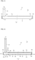
- Fig. 5 is a cross-sectional view that illustrates a configuration of the refrigerant distributor 31 provided in the outdoor heat exchanger 3 illustrated in Fig. 3 .
- Fig. 6 is a cross-sectional view that illustrates a configuration of the refrigerant distributor 32 provided in the outdoor heat exchanger 3 illustrated in Fig. 3 .
- the plurality of flat tubes 37 included in the heat exchange body 33A each have tube end portions 37a and 37b at both respective ends in the axial direction.
- the refrigerant distributor 31 is provided under, between the tube end portions 37a and 37b, the tube end portion 37a, which is lower than the tube end portion 37b.
- the refrigerant distributor 31 is, as illustrated in Fig. 5 , formed by an outer tube 51 and a connection tube 52.
- the refrigerant distributor 31 has a single-tube structure.
- the outer tube 51 is a circular tube and its axial direction is the X direction.
- a plurality of flat-tube insertion holes 51e are provided in an upper face portion of the outer tube 51.
- connection tube 52 is, as illustrated in Fig. 5 , connected to the outer tube 51.
- An axial direction of the connection tube 52 is the Z direction.
- a lower end portion 52a of the connection tube 52 is inserted into the outer tube 51.
- An internal space in the connection tube 52 and an internal space in the outer tube 51 communicate with each other.
- the refrigerant distributor 31 is, as illustrated in Fig. 2 , connected to the refrigerant pipe 35.
- the outer tube 51 of the refrigerant distributor 31 is connected to the refrigerant pipe 35 through the connection tube 52.
- An inside of the refrigerant distributor 31 is, as illustrated in Fig. 5 , one space formed by the internal space in the connection tube 52 and the internal space in the outer tube 51.
- Refrigerant having flowed from the refrigerant pipe 35 into the space inside the refrigerant distributor 31 is directly distributed to the plurality of flat tubes 37 included in the heat exchange body 33A.
- the reverse header 34 thus allows directions in which refrigerant flows to be switched.
- An example is herein provided in which the flat tubes 37 located leeward and the flat tubes 37 located windward are connected through the reverse header 34; however, the configuration is not limited to such a case.
- the flat tubes 37 may also not be divided into windward ones and leeward ones and may also be formed by one flat tube. The case in which the flat tube 37 is formed by one flat tube is described later in Embodiment 2 with reference to Fig. 19 .
- the refrigerant distributor 32 is provided under the tube end portions 37a, which are lower portions of the plurality of flat tubes 37 included in the heat exchange body 33B.
- the refrigerant distributor 32 is, as illustrated in Fig. 6 , formed by the outer tube 53, an inner tube 54, and a connection tube 56.
- the refrigerant distributor 32 has a double-tube structure.
- the outer tube 53 is a circular tube and its axial direction is the X direction.
- a plurality of flat-tube insertion holes 53e are provided in an upper face portion of the outer tube 53.
- the plurality of flat-tube insertion holes 53e are spaced from each other and arranged in the X direction.
- the plurality of flat-tube insertion holes 53e are through holes that pass through the upper face portion of the outer tube 53.
- the tube end portion 37a of each of the flat tubes 37 is directly inserted into a flat-tube insertion hole 53e of the outer tube 53.
- a closure plate 53c is provided between the tube end portions 53a and 53b of the outer tube 53, at the tube end portion 53a, a closure plate 53c is provided and, at the tube end portion 53b, a closure plate 53d is provided.
- the tube end portion 53a and the tube end portion 53b are each in a closed state by the closure plate 53c and the closure plate 53d, respectively, and are not open.
- connection tube 56 is, as illustrated in Fig. 6 , connected to the outer tube 53.
- An axial direction of the connection tube 56 is the Z direction.
- a lower end portion 56a of the connection tube 56 is inserted into the outer tube 53.
- An internal space in the connection tube 56 and a first internal space 53g which is an internal space that faces the tube end portion 53a of the outer tube 53, communicate with each other.
- a cross-sectional shape of the first internal space 53g is circular.
- the refrigerant distributor 32 is, as illustrated in Fig. 2 , connected to the refrigerant pipe 36.
- the outer tube 53 of the refrigerant distributor 32 is connected to the refrigerant pipe 36 through the connection tube 56.
- the refrigerant distributor 32 has a double-tube structure such that, inside the outer tube 53, the inner tube 54 is located. Between an internal wall 53f of the outer tube 53 and an external wall 54f of the inner tube 54, a gap is defined as a second internal space 53h in the outer tube 53. A cross-sectional shape of the second internal space 53h is doughnut-shaped, that is, ring-shaped.
- the inner tube 54 is provided with a plurality of refrigerant outflow holes 54c arranged in parallel to each other in a side face portion of the inner tube 54.
- the inner tube 54 is joined to the outer tube 53 with a partition plate 55 in between.
- the partition plate 55 is located between the first internal space 53g and the closure plate 53d of the outer tube 53.
- the partition plate 55 is, as described above, joined to the internal wall 53f of the outer tube 53 and the external wall 54f of the inner tube 54.
- the refrigerant that flows inside the refrigerant distributor 32 is thus allowed to pass through between the first internal space 53g at the tube end portion 53a to which the connection tube 56 is connected and the closure plate 53d at the opposite tube end portion 53b only through the internal space in the inner tube 54.
- the outdoor heat exchanger 4 is formed by a refrigerant distributor 41, a refrigerant distributor 42, a plurality of heat exchange bodies 43, and a reverse header 44.
- the refrigerant pipe 36 is connected to the refrigerant distributor 41 and a refrigerant pipe 45 is connected to the refrigerant distributor 42.
- the plurality of heat exchange bodies 43 includes, as illustrated in Fig. 4 , a heat exchange body 43A and a heat exchange body 43B.
- the heat exchange body 43A and the heat exchange body 43B are arranged in a direction of airflow and face each other.
- the heat exchange body 43A and the heat exchange body 43B are located such that the two heat exchange bodies form layers in a direction along a direction of wind generated by its corresponding one of the outdoor air-sending devices 9.
- a heat exchange body 43 located windward is referred to as the heat exchange body 43B and a heat exchange body 43 located leeward is referred to as the heat exchange body 43A.
- the heat exchange body 43A and the heat exchange body 43B are basically the same in configuration and are thus collectively described below as the heat exchange body 43.
- the heat exchange body 43 is formed by a plurality of flat tubes 47 and a plurality of fins 48.
- the plurality of flat tubes 47 are spaced from each other and arranged in a horizontal direction, that is, the X direction. This configuration causes wind generated by its corresponding one of the outdoor air-sending devices 9 to flow between the flat tubes 47, which are adjacent to each other, in a direction represented by its corresponding one of outlined arrows illustrated in Fig. 2 .
- the axial direction of the plurality of flat tubes 47 is the Z direction. Refrigerant flows inside the flat tubes 47 in the Z direction. Refrigerant flows inside the flat tubes 47 and the refrigerant and air thus exchange heat with each other.
- the fins 48 are arranged between the flat tubes 47, which are adjacent to each other in the X direction.
- the fins 48 are each joined to a side face portion of the flat tube 47 that is adjacent to the fin 48 and each transfer heat to the flat tube 47.
- the fin 48 such as a corrugated fin, is used to improve efficiency of heat exchange between air and refrigerant.
- the fin 48 is, however, not limited to a corrugated fin and may also be, for example, a flat-plate fin. Also, air and refrigerant exchange heat with each other even at a surface of the flat tube 47, and the fins 48 thus do not necessarily have to be provided. In a case in which the plurality of heat exchange bodies 43 have fins 48, the same fins 48 may also be shared among the plurality of heat exchange bodies 43.
- Fig. 7 is a cross-sectional view that illustrates a configuration of the refrigerant distributor 41 provided in the outdoor heat exchanger 4 illustrated in Fig. 4 .
- Fig. 8 is a cross-sectional view that illustrates a configuration of the refrigerant distributor 42 provided in the outdoor heat exchanger 4 illustrated in Fig. 4 .
- the refrigerant distributor 41 is provided under, between the tube end portions 47a and 47b of each of the plurality of flat tubes 47 included in the heat exchange body 43A, the tube end portion 47a, which is lower than the tube end portion 47b.
- the refrigerant distributor 41 is, as illustrated in Fig. 7 , formed by the outer tube 57, an inner tube 58, and a connection tube 60.
- the refrigerant distributor 41 has a double-tube structure.
- the outer tube 57 is a circular tube and its axial direction is the X direction.
- a plurality of flat-tube insertion holes 57e are provided in an upper face portion of the outer tube 57.
- the plurality of flat-tube insertion holes 57e are spaced from each other and arranged in the X direction.
- the plurality of flat-tube insertion holes 57e are through holes that pass through the upper face portion of the outer tube 57.
- the tube end portion 47a of each of the flat tubes 47 is directly inserted into a flat-tube insertion hole 57e of the outer tube 57.
- a closure plate 57c is provided between the tube end portions 57a and 57b of the outer tube 57, at the tube end portion 57a, a closure plate 57c is provided and, at the tube end portion 57b, a closure plate 57d is provided.
- the tube end portion 57a and the tube end portion 57b are each in a closed state by the closure plate 57c and the closure plate 57d, respectively, and are not open.
- connection tube 60 is, as illustrated in Fig. 7 , connected to the outer tube 57.
- An axial direction of the connection tube 60 is the Z direction.
- a lower end portion 60a of the connection tube 60 is inserted into the outer tube 57.
- An internal space in the connection tube 60 and a first internal space 57g which is an internal space that faces the tube end portion 57a of the outer tube 57, communicate with each other.
- a cross-sectional shape of the first internal space 57g is circular.
- the refrigerant distributor 41 is, as illustrated in Fig. 2 , connected to the refrigerant pipe 36.
- the outer tube 57 of the refrigerant distributor 41 is connected to the refrigerant pipe 36 through the connection tube 60.
- the refrigerant distributor 41 has a double-tube structure such that, inside the outer tube 57, the inner tube 58 is located. Between an internal wall 57f of the outer tube 57 and an external wall 58f of the inner tube 58, a gap is defined as a second internal space 57h in the outer tube 57. A cross-sectional shape of the second internal space 57h is doughnut-shaped, that is, ring-shaped.
- the inner tube 58 is provided with a plurality of refrigerant outflow holes 58c arranged in parallel to each other in a side face portion of the inner tube 58.
- An inner diameter of the refrigerant outflow hole 58c may also be the same as or different from an inner diameter of the refrigerant outflow hole 54c illustrated in Fig. 6 and the inner diameter of the refrigerant outflow hole 62c illustrated in Fig. 8 .
- the inner tube 58 is joined to the outer tube 57 with a partition plate 59 in between.
- the partition plate 59 is located between the first internal space 57g and the closure plate 57d of the outer tube 57.
- the partition plate 59 partitions an area into the first internal space 57g and the second internal space 57h. In the central portion of the partition plate 59, a through hole 59a is formed.
- the tube end portion 58a is fitted into the through hole 59a.
- the tube end portion 58a opens toward the first internal space 57g.
- the first internal space 57g and an internal space in the inner tube 58 thus communicate with each other.
- the tube end portion 58b of the inner tube 58 is joined to the closure plate 57d and is in a closed state.
- An outer circumference portion of the partition plate 59 is joined to the internal wall 57f of the outer tube 57.
- the partition plate 59 is, as described above, joined to the internal wall 57f of the outer tube 57 and the external wall 58f of the inner tube 58.
- the refrigerant that flows inside the refrigerant distributor 41 is thus allowed to pass through between the first internal space 57g at the tube end portion 57a to which the connection tube 60 is connected and the closure plate 57d at the opposite tube end portion 58b only through the internal space in the inner tube 58.
- the reverse header 44 On top of the tube end portions 47b that are upper ends of the flat tubes 47 in the heat exchange body 43A and on top of the tube end portions 47b that are upper ends of the flat tubes 47 in the heat exchange body 43B, the reverse header 44 is provided.
- the heat exchange body 43A is thus connected to the heat exchange body 43B through the reverse header 44.
- the reverse header 44 has the function of reversing an upward flow of refrigerant into a downward flow by causing refrigerant having flowed in from the plurality of flat tubes 47 included in the heat exchange body 43A to flow out into the plurality of flat tubes 47 included in the heat exchange body 43B.
- the outer tube 57 may be referred to as a first outer tube, the inner tube 58 as a first inner tube, the refrigerant outflow hole 58c as a first refrigerant outflow hole, and the partition plate 59 as a first partition plate.
- the outer tube 61 may be referred to as a second outer tube, the inner tube 62 as a second inner tube, the refrigerant outflow hole 62c as a second refrigerant outflow hole, and the partition plate 63 as a second partition plate.
- the reverse header 44 may be referred to as a first reverse header.
- Refrigerant having flowed into the refrigerant distributor 41 flows, when the refrigerant passes through inside the inner tube 58, out through the refrigerant outflow holes 58c into the second internal space 57h. Subsequently, the refrigerant is distributed from the second internal space 57h into the respective flat tubes 47.
- the inner tube 58 is thus provided with the refrigerant outflow holes 58c, which enables refrigerant to be evenly distributed to the respective flat tubes 47 in the heat exchange body 43A.
- Refrigerant having condensed inside the heat exchange body 43A and the heat exchange body 43B passes through the refrigerant distributor 42 and flows out into the refrigerant pipe 45.
- the refrigerant distributor 41 which is located on an inflow side of the outdoor heat exchanger 4 located downstream between the plurality of outdoor heat exchanger 3 and outdoor heat exchanger 4 that form a series refrigerant flow passage in cooling operation, has a double-tube structure.
- the inner tube 58 in the refrigerant distributor 41 has a large number of refrigerant outflow holes 58c arranged in parallel to each other. This configuration improves the uniformity of distribution of refrigerant in a two-phase gas-liquid state into the heat exchange body 43A in the outdoor heat exchanger 4 located downstream.
- refrigerant distributor 41 refrigerant flows into the first internal space 57g in the outer tube 57 through the connection tube 60. Subsequently, the refrigerant enters the inner tube 58 from the first internal space 57g once and then flows out through a large number of refrigerant outflow holes 58c arranged in parallel to each other included in the inner tube 58 into the second internal space 57h in the outer tube 57. At this time, in the outer tube 57, the second internal space 57h is separated from the first internal space 57g by the partition plate 59.
- This configuration causes the refrigerant having flowed into the second internal space 57h in the outer tube 57 does not flow toward the first internal space 57g and flows out through the flat-tube insertion holes 57e into the plurality of flat tubes 47 connected to the outer tube 57.
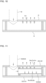
- Fig. 10 is a diagram that schematically illustrates distribution acts of refrigerant at the refrigerant distributor 31 provided in the refrigeration cycle apparatus 100 according to Embodiment 1.
- Fig. 11 is a diagram that schematically illustrates distribution acts of refrigerant at the refrigerant distributor 32, 41, 42 provided in the refrigeration cycle apparatus 100 according to Embodiment 1.
- Fig. 10 and Fig. 11 illustrate a case for clarity in which the refrigerant outflow holes 54c, 58c, 62c open directly downward.
- refrigerant spouts out through a plurality of refrigerant outflow holes 54c, 58c, 62c provided in the inner tube 54, 58, 62.
- This configuration disturbs liquid refrigerant that accumulates inside the outer tube 53, 57, 61 and thus prevents liquid refrigerant from accumulating at a lower portion of the outer tube 51. As a result, the amount of liquid refrigerant that accumulates in the outer tube 51 decreases and refrigerant is thus caused to effectively circulate in the refrigerant circuit.
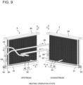
- Fig. 9 is a perspective view that illustrates a connection state in which the outdoor heat exchanger 3 and the outdoor heat exchanger 4 each in a heating operation state are connected to each other in the refrigeration cycle apparatus 100 according to Embodiment 1.
- Fig. 9 illustrates a refrigerant flow passage through which the outdoor heat exchanger 3 and the outdoor heat exchanger 4 are connected to each other, which is expressed by simple connection of refrigerant pipes.
- Solid arrows illustrated in Fig. 9 each represent a direction in which refrigerant flows and outlined arrows illustrated in Fig. 9 each represent a direction of wind generated by its corresponding one of the outdoor air-sending devices 9.
- the outdoor heat exchanger 3 and the outdoor heat exchanger 4 each serve as an evaporator.
- the refrigerant distributor 41 which is provided on an outflow side of the outdoor heat exchanger 4, is a refrigerant distributor structured by a double pipe such that, in its inner tube 58, a large number of the refrigerant outflow holes 58c are arranged in parallel to each other.
- the double-tube structured refrigerant distributor 41 thus increases pressure loss in a refrigerant flow passage and decreases pressure on a suction side of the compressor 1, compared to a case in which a single-tube structured refrigerant distributor is in use as the refrigerant distributor 41. Problems thus arise in that the required amount of work of the compressor 1 is increased and the performance of the refrigeration cycle apparatus is decreased.
- the refrigerant flows through the four-way valve 2 and the refrigerant pipe 306 into the accumulator 10.
- the refrigerant is sucked from the accumulator 10 into the compressor 1 again and circulates in the refrigerant circuit.
- the compressed refrigerant turns into gas refrigerant, is then discharged from the compressor 1, flows through the four-way valve 2 and the refrigerant pipe 305 out from the outdoor unit 101, and flows into the indoor unit 201.
- the refrigerant condenses in the indoor heat exchanger 21 and supplies heating energy to air.
- the refrigerant then flows out from the indoor unit 201 and then flows into the outdoor unit 101.
- the refrigerant branches off into the refrigerant pipe 302 and the refrigerant pipe 304 and the respective branches of the refrigerant flow into the expansion valve 5 and the expansion valve 6.
- a series refrigerant flow passage may also be formed in which the outdoor heat exchangers 3A and 3B and the outdoor heat exchanger 4 are connected in series to each other.
- the flows of refrigerant in this case are opposite to the flows of refrigerant in a cooling operation state described above with reference to Fig. 17 . Their descriptions are thus omitted here.
- the function of the refrigerant distributor 41 prevents a situation in which refrigerant is unevenly distributed to the plurality of flat tubes 47 in the outdoor heat exchanger 4. Refrigerant is thus evenly distributed to the plurality of flat tubes 47, which ensures that the required heat exchange amount is uniform across all faces of the heat exchange body 43 included in the outdoor heat exchanger 4 and that a reduction in heat exchange efficiency is thus prevented.
- the outdoor heat exchanger 4 has the refrigerant distributor 41 and the refrigerant distributor 42.
- the refrigerant distributors 41 and 42 each have a double-tube structure formed by an outer tube and an inner tube. Also, in the inner tubes 58 and 62, the respective refrigerant outflow holes 58c and 62c are formed, through which refrigerant flows from the inner tubes out into the inside of the outer tubes.
- the flat tubes 47 are inserted. Also in a case in which two-phase gas-liquid refrigerant is caused to flow into the refrigerant distributor 41 or 42, the refrigerant is thus evenly distributed to all the flat tubes 47.
- the refrigerant distributor 31 provided in the outdoor heat exchanger 3 is a single-tube structured and is thus designed to reduce pressure loss in cooling operation and heating operation.
- Fig. 19 is a perspective view that illustrates a connection state in which an outdoor heat exchanger 3C and an outdoor heat exchanger 4C are connected to each other in a refrigeration cycle apparatus 100 according to Embodiment 2.
- the configuration of the refrigeration cycle apparatus 100 according to Embodiment 2 is basically the same as the configuration of the refrigeration cycle apparatus 100 according to Embodiment 1.
- Embodiment 2 differs from Embodiment 1 in that, instead of the outdoor heat exchangers 3 and 4 in Embodiment 1, the respective outdoor heat exchangers 3C and 4C are provided in Embodiment 2.
- the other configurations are the same as those in Embodiment 1 and their descriptions are thus omitted here.
- the heat exchange bodies 33 included in the outdoor heat exchanger 3 and the heat exchange bodies 43 included in the outdoor heat exchanger 4 are each located as two layers in a direction along a direction of wind generated by their corresponding one of the outdoor air-sending devices 9.
- a heat exchange body 33 included in the outdoor heat exchanger 3 and a heat exchange body 43 included in the outdoor heat exchanger 4 are each located as a single layer in a direction along a direction of wind generated by its corresponding one of the outdoor air-sending devices 9.
- Fig. 19 illustrates a refrigerant flow passage through which the outdoor heat exchanger 3C and the outdoor heat exchanger 4C are connected in series to each other, which is expressed by simple connection of refrigerant pipes.
- Outlined arrows each represent a direction of wind generated by its corresponding one of the outdoor air-sending devices 9.
- arrows illustrated around a refrigerant pipe 35A, a refrigerant pipe 36A, and a refrigerant pipe 45A represent flows of refrigerant.
- Solid arrows represent flows of refrigerant in cooling operation and dashed arrows represent flows of refrigerant in heating operation.
- the outdoor heat exchanger 3C is formed by a refrigerant distributor 31, a refrigerant distributor 32, and the heat exchange body 33.
- the heat exchange body 33 is formed by a plurality of flat tubes 37 and a plurality of fins 38.
- the configuration of the heat exchange body 33 is as described in Embodiment 1 and its description is thus omitted here.
- the refrigerant distributor 31, which is single-tube structured is provided on top of the heat exchange body 33 and the refrigerant distributor 32, which is double-tube structured, is provided under the heat exchange body 33.
- the refrigerant pipe 35A is connected to the refrigerant distributor 31 through a connection tube 52 and the refrigerant pipe 36A is connected to the refrigerant distributor 32 through a connection tube 56.
- the outdoor heat exchanger 4C is formed by a refrigerant distributor 41, a refrigerant distributor 42, and the heat exchange body 43.
- the heat exchange body 43 is formed by a plurality of flat tubes 47 and a plurality of fins 48.
- the configuration of the heat exchange body 43 is as described in Embodiment 1 and its description is thus omitted here.
- the refrigerant distributor 41 which is double-tube structured, is provided on top of the heat exchange body 43 and the refrigerant distributor 42, which is double-tube structured, is provided under the heat exchange body 43.
- the configurations of the refrigerant distributor 41 and the refrigerant distributor 42 are as described in Embodiment 1 and their description is thus omitted here.
- the refrigerant pipe 36A is connected to the refrigerant distributor 41 through a connection tube 60 and the refrigerant pipe 45A is connected to the refrigerant distributor 42 through a connection tube 64.
- the outdoor heat exchanger 4C may be referred to as a heat exchanger.
- the heat exchange body 43 may be referred to as a first heat exchange body.
- the flat tube 47 may be referred to as a first flat tube.
- the refrigerant distributor 41 may be referred to as a first refrigerant distributor and the refrigerant distributor 42 may be referred to as a second refrigerant distributor.
- an outer tube 57 may be referred to as a first outer tube, an inner tube 58 as a first inner tube, and a partition plate 59 as a first partition plate.
- an outer tube 61 may be referred to as a second outer tube, an inner tube 62 as a second inner tube, and a partition plate 63 as a second partition plate.
- a tube end portion 47c of the flat tube 47, which is inserted into the refrigerant distributor 41, may be referred to as one end portion of a first flat tube and a tube end portion 47d of the flat tube 47, which is inserted into the refrigerant distributor 42, may be referred to as the other end portion of a first flat tube.
- the outdoor heat exchanger 3C may be referred to as a second heat exchanger.
- the heat exchange body 33 may be referred to as a second heat exchange body.
- the flat tube 37 may be referred to as a second flat tube.
- the refrigerant distributor 31 may be referred to as a third refrigerant distributor and the refrigerant distributor 32 may be referred to as a fourth refrigerant distributor.
- an outer tube 51 may be referred to as a third outer tube.
- An outer tube 53 may be referred to as a fourth outer tube, an inner tube 54 as a fourth inner tube, and a partition plate 55 as a fourth partition plate.
- a tube end portion 37c of the flat tube 37, which is inserted into the refrigerant distributor 31, may be referred to as one end portion of a second flat tube and a tube end portion 37d of the flat tube 37, which is inserted into the refrigerant distributor 32, may be referred to as the other end portion of a second flat tube.
- gas refrigerant discharged from the compressor 1, which is referable to Fig. 1 flows from the refrigerant pipe 35A through the connection tube 52 into the refrigerant distributor 31.
- a portion of the refrigerant having flowed in condenses in the outdoor heat exchanger 3 and the refrigerant thus transitions into a two-phase gas-liquid state and flows out through the refrigerant distributor 32 into the refrigerant pipe 36A.
- the refrigerant which remains in a two-phase gas-liquid state, flows into the outdoor heat exchanger 4.
- the refrigerant having flowed into the outdoor heat exchanger 4 is first caused to flow through the connection tube 60 into the refrigerant distributor 41.
- the refrigerant distributor 41 has a double-tube structure such that, in its inner tube 58, a large number of the refrigerant outflow holes 58c are arranged in parallel to each other. Refrigerant having flowed into the refrigerant distributor 41 flows, when the refrigerant passes through inside the inner tube 58, out through the refrigerant outflow holes 58c into the second internal space 57h in the outer tube 57.
- the inner tube 58 is thus provided with the refrigerant outflow holes 58c, which enables refrigerant to be evenly distributed to the respective flat tubes 47 in the heat exchange body 43A. Refrigerant having condensed inside the heat exchange body 43 flows out from the refrigerant distributor 42 through the connection tube 64 into the refrigerant pipe 45A.
- the refrigerant distributor 41 which is located on an inflow side of the outdoor heat exchanger 4C located downstream between the plurality of outdoor heat exchanger 3C and outdoor heat exchanger 4C that form a series refrigerant flow passage in refrigerant operation, has a double-tube structure.
- the inner tube 58 in the refrigerant distributor 41 has a large number of refrigerant outflow holes 58c arranged in parallel to each other. This configuration improves the uniformity of distribution of refrigerant in a two-phase gas-liquid state into the heat exchange body 43 in the outdoor heat exchanger 4C located downstream.
- refrigerant flows in a heating operation state are described below. As seen in comparison of the solid arrows and the dashed arrows illustrated in Fig. 19 , the direction in which refrigerant flows in a heating operation state is opposite the direction in a cooling operation state.
- Both the refrigerant distributor 32 and the refrigerant distributor 42 are each a refrigerant distributor provided with a double-tube structure.
- This configuration improves the uniformity of distribution of refrigerant in the outdoor heat exchanger 4C located upstream and the outdoor heat exchanger 3C located downstream, in which refrigerant in a two-phase gas-liquid state is evenly distributed to the heat exchange body 43 and the heat exchange body 33.
- the refrigerant distributor 41 of the outdoor heat exchanger 4C which is located downstream in a cooling operation state, is double-tube structured, the same advantageous effects are obtained as in Embodiment 1 described above.
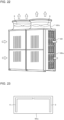
- Fig. 20 is a perspective view that illustrates an external view of an outdoor unit 101 provided in a refrigeration cycle apparatus 100 according to Embodiment 3.
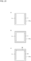
- Fig. 21 includes plan views that schematically illustrate examples of a configuration of the outdoor unit 101 provided in the refrigeration cycle apparatus 100 according to Embodiment 3.
- the outdoor unit 101 has outdoor heat exchangers 3 and 4, refrigerant pipes 35, 36, and 45, which are referable to Fig. 2 and through which the outdoor heat exchangers 3 and 4 are connected to each other, a housing 101a, and an outdoor air-sending device 9.
Landscapes
- Engineering & Computer Science (AREA)
- Mechanical Engineering (AREA)
- General Engineering & Computer Science (AREA)
- Physics & Mathematics (AREA)
- Thermal Sciences (AREA)
- Chemical & Material Sciences (AREA)
- Combustion & Propulsion (AREA)
- Heat-Exchange Devices With Radiators And Conduit Assemblies (AREA)
- Other Air-Conditioning Systems (AREA)
Abstract
Description
- The present disclosure relates to a heat exchanger and a refrigeration cycle apparatus that have a plurality of flat tubes.
- Among refrigeration cycle apparatuses that each have a plurality of heat exchangers, some refrigeration cycle apparatus includes a plurality of groups of heat exchangers, with one or more heat exchangers defined as one group. Such a refrigeration cycle apparatus is referable to, for example,
Patent Literature 1. The heat exchanger in each of the plurality of groups is an air heat exchanger and has an upper header tube, a lower header tube, heat transfer tubes, and fins. - In cooling operation, groups are connected in series to each other and a series refrigerant flow passage is thus formed through which refrigerant is caused to flow in series between groups. All the heat exchangers in the series refrigerant flow passage each have heat transfer tubes through which refrigerant is caused to flow from above to below.
- In heating operation, groups are connected in parallel to each other and a parallel refrigerant flow passage is thus formed through which refrigerant is caused to flow in parallel to respective groups. All the heat exchangers in the parallel refrigerant flow passage each have heat transfer tubes through which refrigerant is caused to flow from below to above.
- Also, in some heat exchanger, a refrigerant distributor structured with a double tube provided with an inner tube and an outer tube is used as a lower header, for example. A plurality of outer tubes are provided. Between outer tubes adjacent to each other among the plurality of outer tubes, a gap is defined. A single inner tube is provided and sequentially connected to the plurality of outer tubes. To the outer tubes, a plurality of heat transfer tubes are connected in a tubular-axial direction of the outer tubes. Refrigerant that has flowed between the inner tube and the outer tubes is distributed to the plurality of heat transfer tubes.
- Patent Literature 1: International Publication No.
2019/008664 - Usually, a case in which a heat exchanger serves as an evaporator, refrigerant in a two-phase gas-liquid state in which gas refrigerant and liquid refrigerant is mixed to each other flows into the heat exchanger. In this case, as a refrigerant distributor located on an inflow side of the heat exchanger, a refrigerant distributor structured with a double tube provided with an inner tube and an outer tube may be used. In the refrigerant distributor structured with a double tube, a large number of refrigerant outflow holes are arranged in parallel to each other in the inner tube. The refrigerant distributor structured with a double tube is formed such that refrigerant is evenly distributed to a plurality of heat transfer tubes included in a heat exchanger and the refrigerant distributor is reduced in capacity.
- On an outflow side of a heat exchanger that serves as an evaporator, a refrigerant distributor structured with a single tube is provided. In a case in which the heat exchanger serves as a condenser, the refrigerant distributor has the function of distributing refrigerant to a plurality of heat transfer tubes included in the heat exchanger.
- However, as in
Patent Literature 1 described above, in a case in which a plurality of heat exchangers are mounted on one outdoor unit, connection states between the plurality of heat exchangers are distinguished between a case in which the series refrigerant flow passage is formed and a case in which the parallel refrigerant flow passage is formed. In a case in which, to perform cooling operation, the plurality of heat exchangers mounted on the outdoor unit each serve as a condenser and the plurality of heat exchangers form with each other the series refrigerant flow passage, a heat exchanger located upstream in a flow passage and a heat exchanger located downstream are different in a state of refrigerant that flows in. That is, into the heat exchanger located upstream, gas refrigerant, which is in a single phase, flows. On the other hand, into the heat exchanger located downstream, refrigerant in a two-phase gas-liquid state in which gas refrigerant and liquid refrigerant is mixed to each other flows, because a portion of the gas refrigerant exchanges heat and thus condenses in the heat exchanger located upstream. The refrigerant distributor on an inflow side of the heat exchanger located downstream in this case, however, is a refrigerant distributor structured with a single tube. In the heat exchanger located downstream, refrigerant caused to flow in is thus not evenly distributed to the plurality of flat tubes included in the heat exchanger. In the heat exchanger located downstream, the amounts of the distributed refrigerant vary at different locations of flat tubes. The heat exchange amount is insufficient around the flat tubes into which a large amount of refrigerant is distributed. The heat exchange amount is excessive around the flat tubes into which a small amount of refrigerant is distributed. Such an uneven distribution causes a problem in that efficiency of heat exchange is reduced. - The present disclosure is made to solve such a problem, and an object of the present disclosure is to provide a refrigeration cycle apparatus and a heat exchanger that is one heat exchanger among a plurality of heat exchangers that each serve as a condenser in cooling operation and is provided with a refrigerant distributor that evenly distributes refrigerant to a plurality of flat tubes also in a case in which, when the plurality of heat exchangers are connected in series to each other and a series refrigerant flow passage is thus formed, the heat exchanger is located downstream in a direction through refrigerant flows.
- A heat exchanger according to one embodiment of the present disclosure includes a first heat exchange body that has a plurality of first flat tubes arranged and spaced from each other in a first direction and each of which tube axis extends in a second direction that intersects the first direction; a first refrigerant distributor into which one end portion of each of the plurality of first flat tubes is inserted; and a second refrigerant distributor into which the other end portion of each of the plurality of first flat tubes is inserted, the first refrigerant distributor having a first outer tube that extends in the first direction and into which the one end portion of each of the plurality of first flat tubes is inserted, a first inner tube that extends in the first direction, is located inside the first outer tube, and has a plurality of first refrigerant outflow holes arranged and spaced from each other in the first direction, and a first partition plate joined to an internal wall of the first outer tube in a state in which the first inner tube passes through a plate thickness, the second refrigerant distributor having a second outer tube that extends in the first direction and into which the other end portion of each of the plurality of first flat tubes is inserted, a second inner tube that extends in the first direction, is located inside the second outer tube, and has a plurality of second refrigerant outflow holes arranged and spaced from each other in the first direction, and a second partition plate joined to an internal wall of the second outer tube in a state in which the second inner tube passes through a plate thickness.
- A refrigeration cycle apparatus according to another embodiment of the present disclosure is provided with an outdoor unit, in which the outdoor unit is provided with the heat exchanger described above, a second heat exchanger, a refrigerant pipe through which the heat exchanger and the second heat exchanger are connected to each other, a housing that is box-shaped and houses the heat exchanger and the second heat exchanger inside, and an air-sending device located at a upper portion of the housing and configured to form a flow of air by being driven to rotate and blow out the air that passes through the heat exchanger and the second heat exchanger upward from an upper face of the housing, and the heat exchanger and the second heat exchanger are located along a part or all of four side faces of the housing.
- The heat exchanger and the refrigeration cycle apparatus according to an embodiment of the present disclosure have a refrigerant distributor structured with a double tube and a plurality of refrigerant outflow holes arranged in parallel to each other in an inner tube of the refrigerant distributor. Also in a case, for example, in which refrigerant in a two-phase gas-liquid state is caused to flow into the heat exchanger, the refrigerant distributor is thus provided, such an uneven situation is therefore addressed in which refrigerant is unevenly distributed to a plurality of flat tubes. Also, refrigerant is thus evenly distributed to the plurality of flat tubes, which ensures that the required heat exchange amount is uniform across all faces of the heat exchange body and that a reduction in heat exchange efficiency is thus prevented.
-
- [
Fig. 1] Fig. 1 is a refrigerant circuit diagram that illustrates a configuration of arefrigeration cycle apparatus 100 according toEmbodiment 1. - [
Fig. 2] Fig. 2 is a perspective view that illustrates a connection state in which anoutdoor heat exchanger 3 and anoutdoor heat exchanger 4 are connected to each other in therefrigeration cycle apparatus 100 according toEmbodiment 1. - [
Fig. 3] Fig. 3 is a cross-sectional view that illustrates a configuration of theoutdoor heat exchanger 3 illustrated inFig. 2 . - [
Fig. 4] Fig. 4 is a cross-sectional view that illustrates a configuration of theoutdoor heat exchanger 4 illustrated inFig. 2 . - [
Fig. 5] Fig. 5 is a cross-sectional view that illustrates a configuration of arefrigerant distributor 31 provided in theoutdoor heat exchanger 3 illustrated inFig. 3 . - [
Fig. 6] Fig. 6 is a cross-sectional view that illustrates a configuration of arefrigerant distributor 32 provided in theoutdoor heat exchanger 3 illustrated inFig. 3 . - [
Fig. 7] Fig. 7 is a cross-sectional view that illustrates a configuration of arefrigerant distributor 41 provided in theoutdoor heat exchanger 4 illustrated inFig. 4 . - [
Fig. 8] Fig. 8 is a cross-sectional view that illustrates a configuration of arefrigerant distributor 42 provided in theoutdoor heat exchanger 4 illustrated inFig. 4 . - [
Fig. 9] Fig. 9 is a perspective view that illustrates a connection state in which theoutdoor heat exchanger 3 and theoutdoor heat exchanger 4 each in a heating operation state are connected to each other in therefrigeration cycle apparatus 100 according toEmbodiment 1. - [
Fig. 10] Fig. 10 is a diagram that schematically illustrates distribution acts of refrigerant at therefrigerant distributor 31 provided in therefrigeration cycle apparatus 100 according toEmbodiment 1. - [
Fig. 11] Fig. 11 is a diagram that schematically illustrates distribution acts of refrigerant at therefrigerant distributor refrigeration cycle apparatus 100 according toEmbodiment 1. - [
Fig. 12] Fig. 12 is a diagram that schematically illustrates the state of liquid refrigerant in therefrigerant distributor 31 provided in therefrigeration cycle apparatus 100 according toEmbodiment 1. - [
Fig. 13] Fig. 13 is a diagram that schematically illustrates the state of liquid refrigerant in therefrigerant distributor refrigeration cycle apparatus 100 according toEmbodiment 1. - [
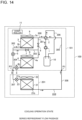
Fig. 14] Fig. 14 is a refrigerant circuit diagram that illustrates a configuration of arefrigeration cycle apparatus 100 according toModification 1 ofEmbodiment 1. - [
Fig. 15] Fig. 15 is a refrigerant circuit diagram that illustrates a configuration of therefrigeration cycle apparatus 100 according toModification 1 ofEmbodiment 1. - [
Fig. 16] Fig. 16 is a refrigerant circuit diagram that illustrates a configuration of arefrigeration cycle apparatus 100 according toModification 2 ofEmbodiment 1. - [
Fig. 17] Fig. 17 is a diagram that illustrates flows of refrigerant in a case in which therefrigeration cycle apparatus 100 according toModification 2 ofEmbodiment 1 is in a cooling operation state. - [
Fig. 18] Fig. 18 illustrates flows of refrigerant in a case in which therefrigeration cycle apparatus 100 according toModification 2 ofEmbodiment 1 is in a heating operation state. - [
Fig. 19] Fig. 19 is a perspective view that illustrates a connection state in which anoutdoor heat exchanger 3C and anoutdoor heat exchanger 4C are connected to each other in arefrigeration cycle apparatus 100 according toEmbodiment 2. - [
Fig. 20] Fig. 20 is a perspective view that illustrates an external view of anoutdoor unit 101 provided in arefrigeration cycle apparatus 100 according toEmbodiment 3. - [
Fig. 21] Fig. 21 includes plan views that schematically illustrate examples of a configuration of theoutdoor unit 101 provided in therefrigeration cycle apparatus 100 according toEmbodiment 3. - [
Fig. 22] Fig. 22 is a perspective view that illustrates an external view of anoutdoor unit 101 provided in arefrigeration cycle apparatus 100 according to Modification ofEmbodiment 3. - [
Fig. 23] Fig. 23 is a plan view that schematically illustrates an example of a configuration of theoutdoor unit 101 provided in therefrigeration cycle apparatus 100 according toEmbodiment 3. - Embodiments of a heat exchanger and a refrigeration cycle apparatus according to the present disclosure are described below with reference to drawings. The present disclosure is not limited to embodiments described below and may be variously changed without departing from the spirit of the present disclosure. The present disclosure also includes any combination of combinable configurations among configurations described in the embodiments and their modifications described below. Also, the same or equivalent elements are denoted by the same reference signs in the drawings. Their descriptions are omitted or simplified as long as resultant descriptions are suited. Furthermore, among a plurality of components or elements of the same kind that are, for example, differentiated by suffixes such as uppercase alphabetic characters postfixed to the reference signs, components or elements not required to be to distinguished or specified in particular may be described without such suffixes. In addition, relative relationships in dimension between components, shapes of components, and other details of components illustrated in the drawings may differ from those of actual components. Shapes, sizes, locations and other details of components illustrated in the drawings may be changed without departing from the scope of the present disclosure as long as resultant configurations are suited.
- Also, in the drawings, each outdoor heat exchanger has a width direction referred to as an X direction, a height direction referred to as a Z direction, and a front-rear direction referred to as a Y direction. The X direction and the Y direction are, for example, horizontal directions. The Z direction is, for example, an up-down direction and may be a vertical direction in some cases. The X direction is a direction in which a plurality of flat tubes are arranged. The Z direction is an axial direction of the flat tube and a direction through which refrigerant flows. The Y direction is a direction through which air flows. The X direction may be referred to as a first direction or a third direction. The Z direction may be referred to as a second direction.
-
Fig. 1 is a refrigerant circuit diagram that illustrates a configuration of arefrigeration cycle apparatus 100 according toEmbodiment 1. Therefrigeration cycle apparatus 100 has anoutdoor unit 101 and anindoor unit 201 and forms a refrigeration cycle such that theoutdoor unit 101 and theindoor unit 201 are connected to each other by arefrigerant pipe 310. In addition, therefrigerant pipe 310 includes a plurality ofrefrigerant pipes 300 to 308. Theserefrigerant pipes 300 to 308 described herein may be collectively referred to as therefrigerant pipe 310. Theoutdoor unit 101 and theindoor unit 201 are connected to each other at connection ports P1 and P2. The connection port P1 and the connection port P2 are each included in therefrigerant pipe 310. The connection port P1 is an inflow connection port through which refrigerant flows into theoutdoor unit 101 when therefrigeration cycle apparatus 100 is in a cooling operation state and is also an outflow connection port through which refrigerant flows out from theoutdoor unit 101 when therefrigeration cycle apparatus 100 is in a heating operation state. The connection port P2 is an outflow connection port through which refrigerant flows out from theoutdoor unit 101 when therefrigeration cycle apparatus 100 is in a cooling operation state and is also an inflow connection port through which refrigerant flows into theoutdoor unit 101 when therefrigeration cycle apparatus 100 is in a heating operation state. In addition,Embodiment 1 describes that oneoutdoor unit 101 and oneindoor unit 201 are provided; however, each of the number of theoutdoor units 101 and the number of theindoor units 201 is not limited to one and may also be two or more. - A refrigerant circuit included in the
refrigeration cycle apparatus 100 is filled with a refrigerant such as a fluorocarbon refrigerant and an HFO refrigerant. - Examples of a fluorocarbon refrigerant include an HFC refrigerant, which stands for fluorinated hydrocarbon or hydrofluorocarbon. Examples of an HFC refrigerant include difluoromethane, which is also referred to as HFC-32 and R32, pentafluoroethane, which is also referred to as HFC-125 and R125, 1,1,1-trifluoroethane, which is also referred to as HFC-143a and R143a, 1,1,1,2-tetrafluoroethane, which is also referred to as HFC-134a and R134a. Furthermore, other examples of a fluorocarbon refrigerant also include a refrigerant mixture in which HFC refrigerants described above are mixed with each other. Examples of a refrigerant mixture include a refrigerant mixture R410A in which R32 and R125 are mixed with each other, a refrigerant mixture R407C in which R32, R125, and R134a are mixed with each other, and a refrigerant mixture R404A in which R125, R143a, and R134a are mixed with each other.
- Examples of a HFO refrigerant, which stands for a hydrofluoroolefin refrigerant, include HFO-1234yf, HFO-1234ze(E), and HFO-1234ze(Z).
- A refrigerant with which the refrigerant circuit included in the
refrigeration cycle apparatus 100 is filled is not limited to the examples described above and any refrigerants used in a vapor-compression heat pump is also usable. Specific examples of usable refrigerants include a CO2 refrigerant, an HC refrigerant, such as a propane refrigerant and an isobutane refrigerant, and an ammonia refrigerant. Furthermore, a refrigerant mixture in which a fluorocarbon refrigerant and an HFO refrigerant are mixed with each other, such as a refrigerant mixture in which R32 and HFO-1234yf are mixed with each other, is also usable as a refrigerant. - The
outdoor unit 101 has acompressor 1, a four-way valve 2, anoutdoor heat exchanger 3, anoutdoor heat exchanger 4, anexpansion valve 5, anexpansion valve 6, asolenoid valve 7, asolenoid valve 8, two outdoor air-sendingdevices 9, anaccumulator 10, and therefrigerant pipes 300 to 306 through which these components are connected to each other. - The
compressor 1 is a fluid machine configured to compress sucked low-pressure refrigerant and discharge the refrigerant as high-pressure refrigerant. Thecompressor 1 is, for example, a rotary compressor or a scroll compressor. In addition, thecompressor 1 may also be, for example, a compressor of which rotational frequency is constant or a compressor of which rotational frequency is controllable with an inverter mounted. - The four-
way valve 2 is a flow switching device provided at a discharge side of thecompressor 1 and configured to switch between a circulation direction of refrigerant in the cooling operation state and a circulation direction of refrigerant in the heating operation state. Fourconnection ports 2a to 2d included in the four-way valve 2 are each connected to its corresponding one of thecompressor 1, theoutdoor heat exchanger 3, theaccumulator 10, and the connection port P1 at which theoutdoor unit 101 and theindoor unit 201 are connected to each other. Among the fourconnection ports 2a to 2d of the four-way valve 2, theconnection port 2a located toward thecompressor 1 is selected to be connected to either theconnection port 2b located toward theoutdoor heat exchanger 3 or theconnection port 2d located toward the connection port P2 of theoutdoor unit 101. Also, between theconnection ports connection port 2c, which is connected to theaccumulator 10. Specifically, in the cooling operation state, theconnection port 2a is connected to theconnection port 2b and theconnection port 2d is connected to theconnection port 2c. In the heating operation state, theconnection port 2a is connected to theconnection port 2d and theconnection port 2b is connected to theconnection port 2c. - The
outdoor heat exchanger 3 is a heat exchanger that allows refrigerant that flows inside and air to exchange heat with each other. Theoutdoor heat exchanger 3 serves as a condenser in the cooling operation state and serves as an evaporator in the heating operation state. Theoutdoor heat exchanger 3 is connected to the four-way valve 2 through therefrigerant pipe 300. Therefrigerant pipe 300 is branched from between theoutdoor heat exchanger 3 and the four-way valve 2 to therefrigerant pipe 301. Therefrigerant pipe 301 is connected to thesolenoid valve 8. Theoutdoor heat exchanger 3 hasconnection ports connection port 3a is connected to the four-way valve 2. Theconnection port 3b located across inside from theopposite connection port 3a is connected to theexpansion valve 5 through therefrigerant pipe 302. Therefrigerant pipe 302 is branched from between theoutdoor heat exchanger 3 and theexpansion valve 5 to therefrigerant pipe 303. Therefrigerant pipe 303 is connected to thesolenoid valve 7. When wind generated by the outdoor air-sendingdevices 9 passes through theoutdoor heat exchanger 3, theoutdoor heat exchanger 3 allows air that passes through and refrigerant that flows inside to exchange heat with each other. The outdoor air-sendingdevices 9 are, for example, centrifugal fans, such as sirocco fans and turbo fans, cross-flow fans, diagonal-flow fans, or propeller fans. In addition, theoutdoor heat exchanger 3 corresponds to a second heat exchanger described inEmbodiment 1. - The
outdoor heat exchanger 4 is a heat exchanger that allows refrigerant that flows inside and air to exchange heat with each other. Theoutdoor heat exchanger 4 serves as a condenser in the cooling operation state and serves as an evaporator in the heating operation state. Theoutdoor heat exchanger 4 is connected to thesolenoid valve 8 through therefrigerant pipe 301. Therefrigerant pipe 301 is branched from between theoutdoor heat exchanger 4 and thesolenoid valve 8 to therefrigerant pipe 303 described above. Theoutdoor heat exchanger 4 hasconnection ports connection port 4a is connected to the four-way valve 2 through thesolenoid valve 8. Theconnection port 4b located across inside from theopposite connection port 4a is connected to theexpansion valve 6 through therefrigerant pipe 304. When wind generated by the outdoor air-sendingdevices 9 passes through theoutdoor heat exchanger 4, theoutdoor heat exchanger 4 allows air that passes through and refrigerant that flows inside to exchange heat with each other. In addition, theoutdoor heat exchanger 4 corresponds to a heat exchanger described inEmbodiment 1. Therefrigerant pipe 304 provided with theexpansion valve 6 is joined to therefrigerant pipe 302 provided withexpansion valve 5. A junction at which therefrigerant pipe 304 and therefrigerant pipe 302 are joined to each other is connected to the connection port P2. The connection port P2 is an outflow connection port through which refrigerant flows out from theoutdoor unit 101 in the cooling operation state and is also an inflow connection port through which refrigerant flows into theoutdoor unit 101 in the heating operation state. - The
expansion valve 5 and theexpansion valve 6 are each configured to serve as a pressure reducing valve or an expansion valve and reduce the pressure of refrigerant and thus expand the refrigerant. Theexpansion valve 5 and theexpansion valve 6 are each, for example, a pressure reducing device such as a linear electronic expansion valve of which opening degree is multi-stepwise or serially adjustable. - The
solenoid valve 7 and thesolenoid valve 8 are each configured to open and close a flow passage depending on whether voltage is applied. Thesolenoid valve 7 and thesolenoid valve 8 are configured block and open respective flows of refrigerant and thus switch flow passages of refrigerant. - The
accumulator 10 is provided such that an outflow side of theaccumulator 10 is connected to a suction side of thecompressor 1. Theaccumulator 10 has the function of separating liquid refrigerant and gas refrigerant from each other and storing surplus refrigerant. An inflow side of theaccumulator 10 is connected to theconnection port 2c of the four-way valve 2 through therefrigerant pipe 306. - To the
outdoor unit 101, acontroller 11 is provided. Thecontroller 11 controls acts of thecompressor 1, the four-way valve 2, theexpansion valve 5, theexpansion valve 6, thesolenoid valve 7, thesolenoid valve 8, and the two outdoor air-sendingdevices 9. - A hardware configuration of the
controller 11 is described below. Thecontroller 11 is formed by a processor circuit. The processor circuit is formed by dedicated hardware or a processor. Examples of the dedicated hardware include an application specific integrated circuit, which is also referred to as an ASIC, and a field programmable gate array, which is also referred to as an FPGA. The processor executes a program stored in a memory. Thecontroller 11 has unillustrated memory circuitry. The memory circuitry is formed by a memory. The memory is non-volatile or volatile semiconductor memory such as a random access memory, which is also referred to as a RAM, a read only memory, which is also referred to as a ROM, a flash memory, and an erasable programmable ROM, which is also referred to as an EPROM, or a disk such as a magnetic disk, a flexible disk, and an optical disk. - The
indoor unit 201 is formed by anindoor heat exchanger 21, an indoor air-sendingdevice 22, anexpansion valve 23, and therefrigerant pipes indoor unit 201 forms, together with theoutdoor unit 101, a refrigeration cycle. Theindoor unit 201 supplies cooling energy or heating energy from theoutdoor unit 101 to a cooling load or a heating load. In addition, the refrigerant load and the heating load correspond to, for example, an indoor space in which theindoor unit 201 is located. - The
indoor heat exchanger 21 is a heat exchanger that allows refrigerant that flows inside and air to exchange heat with each other. Theindoor heat exchanger 21 serves as an evaporator in the cooling operation state and serves as a condenser in the heating operation state. Theindoor heat exchanger 21 hasconnection ports connection port 21a is connected to theexpansion valve 23 through therefrigerant pipe 307. Theconnection port 21b located across inside from theopposite connection port 21a is connected to the connection port P1 through therefrigerant pipe 308. When wind generated by the indoor air-sendingdevice 22 passes through theindoor heat exchanger 21, theindoor heat exchanger 21 allows air that passes through and refrigerant that flows inside to exchange heat with each other. The indoor air-sendingdevice 22 is, for example, a centrifugal fan, such as a sirocco fan and a turbo fan, a cross-flow fan, a diagonal-flow fan, or a propeller fan. - The
expansion valve 23 is configured to serve as a pressure reducing valve or an expansion valve and reduce the pressure of refrigerant and thus expand the refrigerant. Theexpansion valve 23 is, for example, a pressure reducing device such as a linear electronic expansion valve of which opening degree is multi-stepwise or serially adjustable. - When the
refrigeration cycle apparatus 100 is in a cooling operation state, thecontroller 11 exercises control such that theexpansion valve 5 is in a fully closed state, thesolenoid valve 7 is in an open state, thesolenoid valve 8 is in a closed state, and theexpansion valve 6 is in a fully open state. Thecompressor 1 sucks in refrigerant from theaccumulator 10 and then compresses the refrigerant. The compressed refrigerant turns into gas refrigerant, is then discharged from thecompressor 1, and flows into theoutdoor heat exchanger 3 through the four-way valve 2. In theoutdoor heat exchanger 3, a portion of the gas refrigerant condenses and the gas refrigerant then turns into a two-phase gas-liquid state of gas refrigerant and liquid refrigerant. The refrigerant in a two-phase gas-liquid state passes through thesolenoid valve 7 and then flows into theoutdoor heat exchanger 4. The refrigerant compressed in theoutdoor heat exchanger 4 turns into refrigerant in a liquid state. The refrigerant in a liquid state passes through theexpansion valve 6, then flows out from theoutdoor unit 101, and flows into theindoor unit 201. In theindoor unit 201, the refrigerant is reduced in pressure in theexpansion valve 23, then evaporates in theindoor heat exchanger 21, and supplies cooling energy to air. The refrigerant flows out from theindoor unit 201, then flows into theoutdoor unit 101, passes through therefrigerant pipe 305, and flows into the four-way valve 2. Subsequently, the refrigerant flows out from the four-way valve 2, passes through therefrigerant pipe 306, and flows into theaccumulator 10. The refrigerant is then sucked from theaccumulator 10 into thecompressor 1 again and circulates in the refrigerant circuit. This operation establishes a refrigerant circuit that has a refrigerant flow passage through which theoutdoor heat exchanger 3 and theoutdoor heat exchanger 4 are connected in series to each other. - When the
refrigeration cycle apparatus 100 is in a heating operation state, a direction in which refrigerant flows is opposite to a direction in which refrigerant flows in a cooling operation state. Similarly to the states in a cooling operation state, thecontroller 11 exercises control such that theexpansion valve 5 is in a fully closed state, thesolenoid valve 7 is in an open state, thesolenoid valve 8 is in a closed state, and theexpansion valve 6 is in a fully open state. Thecompressor 1 sucks in refrigerant from theaccumulator 10 and then compresses the refrigerant. The compressed refrigerant turns into gas refrigerant, is then discharged from thecompressor 1, and flows out through the four-way valve 2 from theoutdoor unit 101 into theindoor unit 201. In theindoor unit 201, heat is exchanged at theindoor heat exchanger 21 and the refrigerant thus condenses. The refrigerant flows into theexpansion valve 23 and is then reduced in pressure in theexpansion valve 23. Subsequently, the refrigerant flows out from theindoor unit 201 and then flows into theoutdoor unit 101. In theoutdoor unit 101, the refrigerant flows into theoutdoor heat exchanger 4 through theexpansion valve 6 and then evaporates by heat exchange. Subsequently, the refrigerant passes through thesolenoid valve 7 and then flows into theoutdoor heat exchanger 3. The refrigerant of which heat is further exchanged at theoutdoor heat exchanger 3 turns into refrigerant in a gas state. The refrigerant in a gas state flows into the four-way valve 2. Subsequently, the refrigerant flows out from the four-way valve 2, passes through therefrigerant pipe 306, and flows into theaccumulator 10. The refrigerant is then sucked from theaccumulator 10 into thecompressor 1 again and circulates in the refrigerant circuit. This operation establishes a refrigerant circuit that has a refrigerant flow passage through which theoutdoor heat exchanger 3 and theoutdoor heat exchanger 4 are connected in series to each other. - A case is described in "Heating Operation State in Case of Series Refrigerant Flow Passage" in which a series refrigerant flow passage is formed in which the
outdoor heat exchanger 3 and theoutdoor heat exchanger 4 are connected in series to each other. A state of connection, however, is not limited to such a case. That is, a configuration may also be established such that, depending on an operation state of therefrigeration cycle apparatus 100, connection between theoutdoor heat exchanger 3 and theoutdoor heat exchanger 4 may also be switched to connection by use of a series refrigerant flow passage or connection by use of a parallel refrigerant flow passage. Furthermore, in a heating operation state, a parallel refrigerant flow passage may also be formed in which theoutdoor heat exchanger 3 and theoutdoor heat exchanger 4 are connected in parallel to each other. This case is described later with reference toFig. 14 andFig. 15 . -
Fig. 2 is a perspective view that illustrates a connection state in which theoutdoor heat exchanger 3 and theoutdoor heat exchanger 4 are connected to each other in therefrigeration cycle apparatus 100 according toEmbodiment 1.Fig. 2 illustrates a case in which therefrigeration cycle apparatus 100 is in a cooling operation state.Fig. 2 illustrates a refrigerant flow passage through which theoutdoor heat exchanger 3 and theoutdoor heat exchanger 4 are connected in series to each other, which is expressed by simple connection of refrigerant pipes. Solid arrows illustrated inFig. 2 each represent a direction in which refrigerant flows and outlined arrows illustrated inFig. 2 each represent a direction of wind generated by its corresponding one of the outdoor air-sendingdevices 9, that is, a direction of airflow.Fig. 3 is a cross-sectional view that illustrates a configuration of theoutdoor heat exchanger 3 illustrated inFig. 2 .Fig. 4 is a cross-sectional view that illustrates a configuration of theoutdoor heat exchanger 4 illustrated inFig. 2 . - First, the configuration of the
outdoor heat exchanger 3 is described below. As illustrated inFig. 2 andFig. 3 , theoutdoor heat exchanger 3 is formed by arefrigerant distributor 31, arefrigerant distributor 32, a plurality ofheat exchange bodies 33, and areverse header 34. As illustrated inFig. 2 , arefrigerant pipe 35 is connected to therefrigerant distributor 31 and arefrigerant pipe 36 is connected to therefrigerant distributor 32. - The plurality of
heat exchange bodies 33 includes, as illustrated inFig. 3 , a heat exchange body 33A and a heat exchange body 33B. The heat exchange body 33A and the heat exchange body 33B are arranged in a direction of airflow and face each other. In other words, the heat exchange body 33A and the heat exchange body 33B are located such that the two heat exchange bodies form layers in a direction along a direction of wind generated by its corresponding one of the outdoor air-sendingdevices 9. In following description, aheat exchange body 33 located windward is referred to as the heat exchange body 33B and aheat exchange body 33 located leeward is referred to as the heat exchange body 33A. The heat exchange body 33A and the heat exchange body 33B are basically the same in configuration and are thus collectively described below as theheat exchange body 33. - The
heat exchange body 33 is formed by a plurality offlat tubes 37 and a plurality offins 38. The plurality offlat tubes 37 are spaced from each other and arranged in a horizontal direction, that is, the X direction. This configuration causes wind generated by its corresponding one of the outdoor air-sendingdevices 9 to flow between theflat tubes 37, which are adjacent to each other, in a direction represented by its corresponding one of outlined arrows illustrated inFig. 2 . The axial direction of the plurality offlat tubes 37 is the Z direction. Refrigerant flows inside theflat tubes 37 in the Z direction. Refrigerant flows inside theflat tubes 37 and the refrigerant and air thus exchange heat with each other. - The
fins 38 are arranged between theflat tubes 37, which are adjacent to each other in the X direction. Thefins 38 are each joined to a side face portion of theflat tube 37 that is adjacent to thefin 38 and each transfer heat to theflat tube 37. In addition, thefin 38, such as a corrugated fin, is used to improve efficiency of heat exchange between air and refrigerant. Thefin 38 is, however, not limited to a corrugated fin and may also be, for example, a flat-plate fin. Also, air and refrigerant exchange heat with each other even at a surface of theflat tube 37, and thefins 38 thus do not necessarily have to be provided. In a case in which the plurality ofheat exchange bodies 33 havefins 38, thesame fins 38 may also be shared among the plurality ofheat exchange bodies 33. -
Fig. 5 is a cross-sectional view that illustrates a configuration of therefrigerant distributor 31 provided in theoutdoor heat exchanger 3 illustrated inFig. 3 .Fig. 6 is a cross-sectional view that illustrates a configuration of therefrigerant distributor 32 provided in theoutdoor heat exchanger 3 illustrated inFig. 3 . - As illustrated in
Fig. 3 , the plurality offlat tubes 37 included in the heat exchange body 33A each havetube end portions refrigerant distributor 31 is provided under, between thetube end portions tube end portion 37a, which is lower than thetube end portion 37b. Therefrigerant distributor 31 is, as illustrated inFig. 5 , formed by anouter tube 51 and aconnection tube 52. Therefrigerant distributor 31 has a single-tube structure. Theouter tube 51 is a circular tube and its axial direction is the X direction. In an upper face portion of theouter tube 51, a plurality of flat-tube insertion holes 51e are provided. The plurality of flat-tube insertion holes 51e are spaced from each other and arranged in the X direction. The plurality of flat-tube insertion holes 51e are through holes that pass through the upper face portion of theouter tube 51. Thetube end portion 37a of each of theflat tubes 37 is directly inserted into a flat-tube insertion hole 51e of theouter tube 51. Theouter tube 51 hastube end portions tube end portions tube end portion 51a, aclosure plate 51c is provided and, at thetube end portion 51b, aclosure plate 51d is provided. Thetube end portion 51a and thetube end portion 51b are each in a closed state by theclosure plate 51c and theclosure plate 51d, respectively, and are not open. - The
connection tube 52 is, as illustrated inFig. 5 , connected to theouter tube 51. An axial direction of theconnection tube 52 is the Z direction. Alower end portion 52a of theconnection tube 52 is inserted into theouter tube 51. An internal space in theconnection tube 52 and an internal space in theouter tube 51 communicate with each other. As described above, therefrigerant distributor 31 is, as illustrated inFig. 2 , connected to therefrigerant pipe 35. Specifically, theouter tube 51 of therefrigerant distributor 31 is connected to therefrigerant pipe 35 through theconnection tube 52. An inside of therefrigerant distributor 31 is, as illustrated inFig. 5 , one space formed by the internal space in theconnection tube 52 and the internal space in theouter tube 51. Refrigerant having flowed from therefrigerant pipe 35 into the space inside therefrigerant distributor 31 is directly distributed to the plurality offlat tubes 37 included in the heat exchange body 33A. - In addition, the
outer tube 51 is herein illustrated as a shape of one circular cylinder with both ends closed by lids, which are theclosure plates outer tube 51 does not necessarily have to be circular and may also be rectangular or elliptical. Also, theouter tube 51 does not necessarily have to be formed by one cylindrical part. Theouter tube 51 may also be divided into two portions such as an upper half into which theflat tubes 37 are inserted and the other half, that is, a lower half, and may also be formed by joining the upper half and the lower half to each other. The same also applies to anouter tube 53, anouter tube 57, and anouter tube 61, which are described later. - On top of the
tube end portions 37b of theflat tubes 37 in the heat exchange body 33A and on top of thetube end portions 37b of theflat tubes 37 in the heat exchange body 33B, thereverse header 34 is provided. The heat exchange body 33A is thus connected to the heat exchange body 33B through thereverse header 34. Thereverse header 34 has the function of reversing an upward flow of refrigerant into a downward flow by causing refrigerant having flowed in from the plurality offlat tubes 37 included in the heat exchange body 33A to flow out into the plurality offlat tubes 37 included in the heat exchange body 33B. Specifically, in the plurality offlat tubes 37 included in the heat exchange body 33A, refrigerant flows from a lower position toward a higher position in the Z direction. On the other hand, in the plurality offlat tubes 37 included in the heat exchange body 33B, refrigerant flows from a higher position toward a lower position in the Z direction. Thereverse header 34 thus allows directions in which refrigerant flows to be switched. An example is herein provided in which theflat tubes 37 located leeward and theflat tubes 37 located windward are connected through thereverse header 34; however, the configuration is not limited to such a case. Theflat tubes 37 may also not be divided into windward ones and leeward ones and may also be formed by one flat tube. The case in which theflat tube 37 is formed by one flat tube is described later inEmbodiment 2 with reference toFig. 19 . - As illustrated in
Fig. 3 , therefrigerant distributor 32 is provided under thetube end portions 37a, which are lower portions of the plurality offlat tubes 37 included in the heat exchange body 33B. Therefrigerant distributor 32 is, as illustrated inFig. 6 , formed by theouter tube 53, aninner tube 54, and aconnection tube 56. Therefrigerant distributor 32 has a double-tube structure. Theouter tube 53 is a circular tube and its axial direction is the X direction. In an upper face portion of theouter tube 53, a plurality of flat-tube insertion holes 53e are provided. The plurality of flat-tube insertion holes 53e are spaced from each other and arranged in the X direction. The plurality of flat-tube insertion holes 53e are through holes that pass through the upper face portion of theouter tube 53. Thetube end portion 37a of each of theflat tubes 37 is directly inserted into a flat-tube insertion hole 53e of theouter tube 53. Between thetube end portions outer tube 53, at thetube end portion 53a, aclosure plate 53c is provided and, at thetube end portion 53b, aclosure plate 53d is provided. Thetube end portion 53a and thetube end portion 53b are each in a closed state by theclosure plate 53c and theclosure plate 53d, respectively, and are not open. - The
connection tube 56 is, as illustrated inFig. 6 , connected to theouter tube 53. An axial direction of theconnection tube 56 is the Z direction. Alower end portion 56a of theconnection tube 56 is inserted into theouter tube 53. An internal space in theconnection tube 56 and a firstinternal space 53g, which is an internal space that faces thetube end portion 53a of theouter tube 53, communicate with each other. A cross-sectional shape of the firstinternal space 53g is circular. As described above, therefrigerant distributor 32 is, as illustrated inFig. 2 , connected to therefrigerant pipe 36. Specifically, theouter tube 53 of therefrigerant distributor 32 is connected to therefrigerant pipe 36 through theconnection tube 56. - Also, the
refrigerant distributor 32 has a double-tube structure such that, inside theouter tube 53, theinner tube 54 is located. Between aninternal wall 53f of theouter tube 53 and anexternal wall 54f of theinner tube 54, a gap is defined as a secondinternal space 53h in theouter tube 53. A cross-sectional shape of the secondinternal space 53h is doughnut-shaped, that is, ring-shaped. Theinner tube 54 is provided with a plurality ofrefrigerant outflow holes 54c arranged in parallel to each other in a side face portion of theinner tube 54. Theinner tube 54 is joined to theouter tube 53 with apartition plate 55 in between. Thepartition plate 55 is located between the firstinternal space 53g and theclosure plate 53d of theouter tube 53. Thepartition plate 55 partitions an area into the firstinternal space 53g and the secondinternal space 53h. In the central portion of thepartition plate 55, a throughhole 55a is formed. Between thetube end portions inner tube 54, thetube end portion 54a is fitted into the throughhole 55a. Thetube end portion 54a opens toward the firstinternal space 53g. The firstinternal space 53g and an internal space in theinner tube 54 thus communicate with each other. Also, thetube end portion 54b of theinner tube 54 is joined to theclosure plate 53d and is in a closed state. An outer circumference portion of thepartition plate 55 is joined to theinternal wall 53f of theouter tube 53. Thepartition plate 55 is, as described above, joined to theinternal wall 53f of theouter tube 53 and theexternal wall 54f of theinner tube 54. The refrigerant that flows inside therefrigerant distributor 32 is thus allowed to pass through between the firstinternal space 53g at thetube end portion 53a to which theconnection tube 56 is connected and theclosure plate 53d at the oppositetube end portion 53b only through the internal space in theinner tube 54. - Next, the configuration of the
outdoor heat exchanger 4 is described below. As illustrated inFig. 2 andFig. 4 , theoutdoor heat exchanger 4 is formed by arefrigerant distributor 41, arefrigerant distributor 42, a plurality ofheat exchange bodies 43, and areverse header 44. As illustrated inFig. 2 , therefrigerant pipe 36 is connected to therefrigerant distributor 41 and arefrigerant pipe 45 is connected to therefrigerant distributor 42. - The plurality of
heat exchange bodies 43 includes, as illustrated inFig. 4 , a heat exchange body 43A and a heat exchange body 43B. The heat exchange body 43A and the heat exchange body 43B are arranged in a direction of airflow and face each other. In other words, the heat exchange body 43A and the heat exchange body 43B are located such that the two heat exchange bodies form layers in a direction along a direction of wind generated by its corresponding one of the outdoor air-sendingdevices 9. In following description, aheat exchange body 43 located windward is referred to as the heat exchange body 43B and aheat exchange body 43 located leeward is referred to as the heat exchange body 43A. The heat exchange body 43A and the heat exchange body 43B are basically the same in configuration and are thus collectively described below as theheat exchange body 43. - The
heat exchange body 43 is formed by a plurality offlat tubes 47 and a plurality offins 48. The plurality offlat tubes 47 are spaced from each other and arranged in a horizontal direction, that is, the X direction. This configuration causes wind generated by its corresponding one of the outdoor air-sendingdevices 9 to flow between theflat tubes 47, which are adjacent to each other, in a direction represented by its corresponding one of outlined arrows illustrated inFig. 2 . The axial direction of the plurality offlat tubes 47 is the Z direction. Refrigerant flows inside theflat tubes 47 in the Z direction. Refrigerant flows inside theflat tubes 47 and the refrigerant and air thus exchange heat with each other. - The
fins 48 are arranged between theflat tubes 47, which are adjacent to each other in the X direction. Thefins 48 are each joined to a side face portion of theflat tube 47 that is adjacent to thefin 48 and each transfer heat to theflat tube 47. In addition, thefin 48, such as a corrugated fin, is used to improve efficiency of heat exchange between air and refrigerant. Thefin 48 is, however, not limited to a corrugated fin and may also be, for example, a flat-plate fin. Also, air and refrigerant exchange heat with each other even at a surface of theflat tube 47, and thefins 48 thus do not necessarily have to be provided. In a case in which the plurality ofheat exchange bodies 43 havefins 48, thesame fins 48 may also be shared among the plurality ofheat exchange bodies 43. -
Fig. 7 is a cross-sectional view that illustrates a configuration of therefrigerant distributor 41 provided in theoutdoor heat exchanger 4 illustrated inFig. 4 .Fig. 8 is a cross-sectional view that illustrates a configuration of therefrigerant distributor 42 provided in theoutdoor heat exchanger 4 illustrated inFig. 4 . - As illustrated in
Fig. 4 , therefrigerant distributor 41 is provided under, between thetube end portions flat tubes 47 included in the heat exchange body 43A, thetube end portion 47a, which is lower than thetube end portion 47b. Therefrigerant distributor 41 is, as illustrated inFig. 7 , formed by theouter tube 57, aninner tube 58, and aconnection tube 60. Therefrigerant distributor 41 has a double-tube structure. Theouter tube 57 is a circular tube and its axial direction is the X direction. In an upper face portion of theouter tube 57, a plurality of flat-tube insertion holes 57e are provided. The plurality of flat-tube insertion holes 57e are spaced from each other and arranged in the X direction. The plurality of flat-tube insertion holes 57e are through holes that pass through the upper face portion of theouter tube 57. Thetube end portion 47a of each of theflat tubes 47 is directly inserted into a flat-tube insertion hole 57e of theouter tube 57. Between thetube end portions outer tube 57, at thetube end portion 57a, aclosure plate 57c is provided and, at thetube end portion 57b, aclosure plate 57d is provided. Thetube end portion 57a and thetube end portion 57b are each in a closed state by theclosure plate 57c and theclosure plate 57d, respectively, and are not open. - The
connection tube 60 is, as illustrated inFig. 7 , connected to theouter tube 57. An axial direction of theconnection tube 60 is the Z direction. Alower end portion 60a of theconnection tube 60 is inserted into theouter tube 57. An internal space in theconnection tube 60 and a firstinternal space 57g, which is an internal space that faces thetube end portion 57a of theouter tube 57, communicate with each other. A cross-sectional shape of the firstinternal space 57g is circular. As described above, therefrigerant distributor 41 is, as illustrated inFig. 2 , connected to therefrigerant pipe 36. Specifically, theouter tube 57 of therefrigerant distributor 41 is connected to therefrigerant pipe 36 through theconnection tube 60. - Also, the
refrigerant distributor 41 has a double-tube structure such that, inside theouter tube 57, theinner tube 58 is located. Between aninternal wall 57f of theouter tube 57 and anexternal wall 58f of theinner tube 58, a gap is defined as a secondinternal space 57h in theouter tube 57. A cross-sectional shape of the secondinternal space 57h is doughnut-shaped, that is, ring-shaped. Theinner tube 58 is provided with a plurality ofrefrigerant outflow holes 58c arranged in parallel to each other in a side face portion of theinner tube 58. An inner diameter of therefrigerant outflow hole 58c may also be the same as or different from an inner diameter of therefrigerant outflow hole 54c illustrated inFig. 6 and the inner diameter of therefrigerant outflow hole 62c illustrated inFig. 8 . Theinner tube 58 is joined to theouter tube 57 with apartition plate 59 in between. Thepartition plate 59 is located between the firstinternal space 57g and theclosure plate 57d of theouter tube 57. Thepartition plate 59 partitions an area into the firstinternal space 57g and the secondinternal space 57h. In the central portion of thepartition plate 59, a throughhole 59a is formed. Between thetube end portions inner tube 58, thetube end portion 58a is fitted into the throughhole 59a. Thetube end portion 58a opens toward the firstinternal space 57g. The firstinternal space 57g and an internal space in theinner tube 58 thus communicate with each other. Also, thetube end portion 58b of theinner tube 58 is joined to theclosure plate 57d and is in a closed state. An outer circumference portion of thepartition plate 59 is joined to theinternal wall 57f of theouter tube 57. Thepartition plate 59 is, as described above, joined to theinternal wall 57f of theouter tube 57 and theexternal wall 58f of theinner tube 58. The refrigerant that flows inside therefrigerant distributor 41 is thus allowed to pass through between the firstinternal space 57g at thetube end portion 57a to which theconnection tube 60 is connected and theclosure plate 57d at the oppositetube end portion 58b only through the internal space in theinner tube 58. - On top of the
tube end portions 47b that are upper ends of theflat tubes 47 in the heat exchange body 43A and on top of thetube end portions 47b that are upper ends of theflat tubes 47 in the heat exchange body 43B, thereverse header 44 is provided. The heat exchange body 43A is thus connected to the heat exchange body 43B through thereverse header 44. Thereverse header 44 has the function of reversing an upward flow of refrigerant into a downward flow by causing refrigerant having flowed in from the plurality offlat tubes 47 included in the heat exchange body 43A to flow out into the plurality offlat tubes 47 included in the heat exchange body 43B. Specifically, in the plurality offlat tubes 47 included in the heat exchange body 43A, refrigerant flows from a lower position toward a higher position in the Z direction. On the other hand, in the plurality offlat tubes 47 included in the heat exchange body 43B, refrigerant flows from a higher position toward a lower position in the Z direction. Thereverse header 44 thus allows directions in which refrigerant flows to be switched. An example is herein provided in which theflat tubes 47 located leeward and theflat tubes 47 located windward are connected through thereverse header 44; however, the configuration is not limited to such a case. Theflat tubes 47 may also not be divided into windward ones and leeward ones and may also be formed by one flat tube. The case in which theflat tube 47 is formed by one flat tube is described later inEmbodiment 2 with reference toFig. 19 . - As illustrated in
Fig. 4 , therefrigerant distributor 42 is provided under, between thetube end portions flat tubes 47 included in the heat exchange body 43B, thetube end portion 47a, which is lower than thetube end portion 47b. Therefrigerant distributor 42 is, as illustrated inFig. 8 , formed by theouter tube 61, aninner tube 62, and aconnection tube 64. Therefrigerant distributor 42 has a double-tube structure. Theouter tube 61 is a circular tube and its axial direction is the X direction. In an upper face portion of theouter tube 61, a plurality of flat-tube insertion holes 61e are provided. The plurality of flat-tube insertion holes 61e are spaced from each other and arranged in the X direction. The plurality of flat-tube insertion holes 61e are through holes that pass through the upper face portion of theouter tube 61. Thetube end portion 47a of each of theflat tubes 47 is directly inserted into a flat-tube insertion hole 61e of theouter tube 61. Between thetube end portions outer tube 61, at thetube end portion 61a, aclosure plate 61c is provided and, at thetube end portion 61b, aclosure plate 61d is provided. Thetube end portion 61a and thetube end portion 61b are each in a closed state by theclosure plate 61c and theclosure plate 61d, respectively, and are not open. - The
connection tube 64 is, as illustrated inFig. 8 , connected to theouter tube 61. An axial direction of theconnection tube 64 is the Z direction. Alower end portion 64a of theconnection tube 64 is inserted into theouter tube 61. An internal space in theconnection tube 64 and a firstinternal space 61g, which is an internal space that faces thetube end portion 61a of theouter tube 61, communicate with each other. A cross-sectional shape of the firstinternal space 61g is circular. As described above, therefrigerant distributor 42 is, as illustrated inFig. 2 , connected to therefrigerant pipe 45. Specifically, theouter tube 61 of therefrigerant distributor 42 is connected to therefrigerant pipe 45 through theconnection tube 64. - Also, the
refrigerant distributor 42 has a double-tube structure such that, inside theouter tube 61, theinner tube 62 is located. Between aninternal wall 61f of theouter tube 61 and anexternal wall 62f of theinner tube 62, a gap is defined as a secondinternal space 61h in theouter tube 61. A cross-sectional shape of the secondinternal space 61h is doughnut-shaped, that is, ring-shaped. Theinner tube 62 is provided with a plurality ofrefrigerant outflow holes 62c arranged in parallel to each other in a side face portion of theinner tube 62. Theinner tube 62 is joined to theouter tube 61 with apartition plate 63 in between. Thepartition plate 63 is located between the firstinternal space 61g and theclosure plate 61d of theouter tube 61. Thepartition plate 63 partitions an area into the firstinternal space 61g and the secondinternal space 61h. In the central portion of thepartition plate 63, a throughhole 63a is formed. Between thetube end portions inner tube 62, thetube end portion 62a is fitted into the throughhole 63a. Thetube end portion 62a opens toward the firstinternal space 61g. The firstinternal space 61g and an internal space in theinner tube 62 thus communicate with each other. Also, thetube end portion 62b of theinner tube 62 is joined to theclosure plate 61d and is in a closed state. An outer circumference portion of thepartition plate 63 is joined to theinternal wall 61f of theouter tube 61. Thepartition plate 63 is, as described above, joined to theinternal wall 61f of theouter tube 61 and theexternal wall 62f of theinner tube 62. The refrigerant that flows inside therefrigerant distributor 42 is thus allowed to pass through between the firstinternal space 61g at thetube end portion 61a to which theconnection tube 64 is connected and theclosure plate 61d at the oppositetube end portion 61b only through the internal space in theinner tube 62. - The
refrigerant distributor 41 and therefrigerant distributor 42 are thus each the same in configuration as therefrigerant distributor 32 illustrated inFig. 6 and formed by theouter tubes inner tubes partition plates connection tubes refrigerant distributor 41, therefrigerant pipe 36 is connected through theconnection tube 60, and, to therefrigerant distributor 42, therefrigerant pipe 45 is connected through theconnection tube 64. - In addition, the
outdoor heat exchanger 4 may be referred to as a heat exchanger. Theheat exchange body 43 may be referred to as a first heat exchange body. Theflat tube 47 may be referred to as a first flat tube. Furthermore, theflat tube 47 connected to therefrigerant distributor 41 may be referred to as a leeward first flat tube and theflat tube 47 connected to therefrigerant distributor 42 may be referred to as a windward first flat tube. Therefrigerant distributor 41 may be referred to as a first refrigerant distributor and therefrigerant distributor 42 may be referred to as a second refrigerant distributor. Also, theouter tube 57 may be referred to as a first outer tube, theinner tube 58 as a first inner tube, therefrigerant outflow hole 58c as a first refrigerant outflow hole, and thepartition plate 59 as a first partition plate. Also, theouter tube 61 may be referred to as a second outer tube, theinner tube 62 as a second inner tube, therefrigerant outflow hole 62c as a second refrigerant outflow hole, and thepartition plate 63 as a second partition plate. Furthermore, thereverse header 44 may be referred to as a first reverse header. Also, thetube end portion 47a of theflat tube 47 that is inserted into therefrigerant distributor 41 may be referred to as one end portion of a first flat tube and thetube end portion 47a of theflat tube 47 that is inserted into therefrigerant distributor 42 may be referred to as the other end portion of a first flat tube. - Also, the
outdoor heat exchanger 3 may be referred to as a second heat exchanger. Theheat exchange body 33 may be referred to as a second heat exchange body. Theflat tube 37 may be referred to as a second flat tube. Furthermore, theflat tube 37 connected to therefrigerant distributor 31 may be referred to as a leeward second flat tube and theflat tube 37 connected to therefrigerant distributor 32 may be referred to as a windward second flat tube. Therefrigerant distributor 31 may be referred to as a third refrigerant distributor and therefrigerant distributor 32 may be referred to as a fourth refrigerant distributor. Also, theouter tube 51 may be referred to as a third outer tube. Theouter tube 53 may be referred to as a fourth outer tube, theinner tube 54 as a fourth inner tube, therefrigerant outflow hole 54c as a fourth refrigerant outflow hole, and thepartition plate 55 as a fourth partition plate. Furthermore, thereverse header 34 may be referred to as a second reverse header. Also, thetube end portion 37a of theflat tube 37 that is inserted into therefrigerant distributor 31 may be referred to as one end portion of a second flat tube and thetube end portion 37a of theflat tube 37 that is inserted into therefrigerant distributor 32 may be referred to as the other end portion of a second flat tube. - Next, refrigerant flows in the
outdoor heat exchanger 3 and theoutdoor heat exchanger 4 are described below. - First, refrigerant flows in a cooling operation state are described below. As described above,
Fig. 2 is a perspective view that illustrates a connection state in which theoutdoor heat exchanger 3 and theoutdoor heat exchanger 4 each in a cooling operation state are connected to each other and flows of refrigerant. As illustrated inFig. 2 , among four connection tubes included in theoutdoor heat exchanger 3 and theoutdoor heat exchanger 4, that is, theconnection tube 52, theconnection tube 56, theconnection tube 60, and theconnection tube 64, theconnection tube 56 and theconnection tube 60 are connected through therefrigerant pipe 36. Refrigerant flows from therefrigerant pipe 35 connected to theconnection tube 52 into theoutdoor heat exchanger 3, in which a portion of the refrigerant then condenses and the refrigerant thus transitions into a two-phase gas-liquid state, and flows out into therefrigerant pipe 36. Subsequently, the refrigerant, which remains in a two-phase gas-liquid state, flows into theoutdoor heat exchanger 4. The refrigerant having flowed into theoutdoor heat exchanger 4 is first caused to flow into therefrigerant distributor 41. Therefrigerant distributor 41 has a double-tube structure such that, in itsinner tube 58, a large number of therefrigerant outflow holes 58c are arranged in parallel to each other. Refrigerant having flowed into therefrigerant distributor 41 flows, when the refrigerant passes through inside theinner tube 58, out through the refrigerant outflow holes 58c into the secondinternal space 57h. Subsequently, the refrigerant is distributed from the secondinternal space 57h into the respectiveflat tubes 47. Theinner tube 58 is thus provided with therefrigerant outflow holes 58c, which enables refrigerant to be evenly distributed to the respectiveflat tubes 47 in the heat exchange body 43A. Refrigerant having condensed inside the heat exchange body 43A and the heat exchange body 43B passes through therefrigerant distributor 42 and flows out into therefrigerant pipe 45. - As described above, the
refrigerant distributor 41, which is located on an inflow side of theoutdoor heat exchanger 4 located downstream between the plurality ofoutdoor heat exchanger 3 andoutdoor heat exchanger 4 that form a series refrigerant flow passage in cooling operation, has a double-tube structure. Theinner tube 58 in therefrigerant distributor 41 has a large number ofrefrigerant outflow holes 58c arranged in parallel to each other. This configuration improves the uniformity of distribution of refrigerant in a two-phase gas-liquid state into the heat exchange body 43A in theoutdoor heat exchanger 4 located downstream. - Specifically, at the
refrigerant distributor 41, refrigerant flows into the firstinternal space 57g in theouter tube 57 through theconnection tube 60. Subsequently, the refrigerant enters theinner tube 58 from the firstinternal space 57g once and then flows out through a large number ofrefrigerant outflow holes 58c arranged in parallel to each other included in theinner tube 58 into the secondinternal space 57h in theouter tube 57. At this time, in theouter tube 57, the secondinternal space 57h is separated from the firstinternal space 57g by thepartition plate 59. This configuration causes the refrigerant having flowed into the secondinternal space 57h in theouter tube 57 does not flow toward the firstinternal space 57g and flows out through the flat-tube insertion holes 57e into the plurality offlat tubes 47 connected to theouter tube 57. - Distribution acts of refrigerant in a single-tube structure and a double-tube structure are described herein.
Fig. 10 is a diagram that schematically illustrates distribution acts of refrigerant at therefrigerant distributor 31 provided in therefrigeration cycle apparatus 100 according toEmbodiment 1.Fig. 11 is a diagram that schematically illustrates distribution acts of refrigerant at therefrigerant distributor refrigeration cycle apparatus 100 according toEmbodiment 1. In addition,Fig. 10 and Fig. 11 illustrate a case for clarity in which therefrigerant outflow holes - As illustrated in
Fig. 10 , in a case of a single-tube structure, refrigerant flows in through one location, that is, theconnection tube 52, and flows out through a plurality of locations, that is, the flat-tube insertion holes 51e. This configuration tends to cause more refrigerant to flow through the flat-tube insertion hole 51e located closer to theconnection tube 52 than through the other flat-tube insertion holes 51e. - On the other hand, as illustrated in
Fig. 11 , in a case of a double-tube structure, refrigerant flows into theouter tube refrigerant outflow holes inner tube tube insertion holes inner tube inner tube -
Fig. 12 is a diagram that schematically illustrates the state of liquid refrigerant in therefrigerant distributor 31 provided in therefrigeration cycle apparatus 100 according toEmbodiment 1.Fig. 13 is a diagram that schematically illustrates the state of liquid refrigerant in therefrigerant distributor refrigeration cycle apparatus 100 according toEmbodiment 1. In addition,Fig. 12 and Fig. 13 illustrate a case for clarity in which therefrigerant outflow holes -
Fig. 12 and Fig. 13 illustrate a case in which two-phase gas-liquid refrigerant flows into therefrigerant distributor 31 and a case in which two-phase gas-liquid refrigerant flows into therefrigerant distributor Fig. 12 , refrigerant contains liquid refrigerant that accumulates at a lower portion of theouter tube 51 and the amount of refrigerant that circulates in the refrigerant circuit may decrease. On the other hand, in a case of a double-tube structure, as illustrated inFig. 13 , refrigerant spouts out through a plurality ofrefrigerant outflow holes inner tube outer tube outer tube 51. As a result, the amount of liquid refrigerant that accumulates in theouter tube 51 decreases and refrigerant is thus caused to effectively circulate in the refrigerant circuit. - In addition, an example illustrated in
Fig. 12 and Fig. 13 is provided as a case of separated flows, of which gas refrigerant and liquid refrigerant flow separately; however, flows of refrigerant are not limited to the example illustrated inFig. 12 and Fig. 13 . Other examples of flows of refrigerant that flows inside therefrigerant distributors - There are two cases for refrigerant that flows out through the
refrigerant outflow holes inner tubes refrigerant outflow holes inner tube refrigerant outflow holes refrigerant outflow holes refrigerant outflow holes refrigerant outflow holes refrigerant outflow holes refrigerant outflow holes refrigerant outflow holes refrigerant outflow holes refrigerant outflow holes inner tube refrigerant outflow holes inner tube inner tube refrigerant outflow holes - Next, refrigerant flows in a heating operation state are described below.
Fig. 9 is a perspective view that illustrates a connection state in which theoutdoor heat exchanger 3 and theoutdoor heat exchanger 4 each in a heating operation state are connected to each other in therefrigeration cycle apparatus 100 according toEmbodiment 1.Fig. 9 illustrates a refrigerant flow passage through which theoutdoor heat exchanger 3 and theoutdoor heat exchanger 4 are connected to each other, which is expressed by simple connection of refrigerant pipes. Solid arrows illustrated inFig. 9 each represent a direction in which refrigerant flows and outlined arrows illustrated inFig. 9 each represent a direction of wind generated by its corresponding one of the outdoor air-sendingdevices 9. - As seen in comparison of
Fig. 2 andFig. 9 , the direction in which refrigerant flows in a heating operation state is opposite the direction in cooling operation. In a heating operation state, refrigerant flows into theoutdoor heat exchanger 3 and theoutdoor heat exchanger 4 through therefrigerant distributor 32 and therefrigerant distributor 42. Both therefrigerant distributor 32 and therefrigerant distributor 42 are each a refrigerant distributor provided with a double-tube structure. - At the
refrigerant distributor 32, refrigerant flows into the firstinternal space 53g in theouter tube 53 through theconnection tube 56. Subsequently, the refrigerant enters theinner tube 54 from the firstinternal space 53g once and then flows out through a large number ofrefrigerant outflow holes 54c arranged in parallel to each other included in theinner tube 54 into the secondinternal space 53h in theouter tube 53. At this time, in theouter tube 53, the secondinternal space 53h is separated from the firstinternal space 53g by thepartition plate 55. This configuration causes the refrigerant having flowed into the secondinternal space 53h in theouter tube 53 does not flow toward the firstinternal space 53g and flows out through the flat-tube insertion holes 53e into the plurality offlat tubes 37 connected to theouter tube 53. - At the
refrigerant distributor 42, refrigerant flows into the firstinternal space 61g in theouter tube 61 through theconnection tube 64. Subsequently, the refrigerant enters theinner tube 62 from the firstinternal space 61g once and then flows out through a large number ofrefrigerant outflow holes 62c arranged in parallel to each other included in theinner tube 62 into the secondinternal space 61h in theouter tube 61. At this time, in theouter tube 61, the secondinternal space 61h is separated from the firstinternal space 61g by thepartition plate 63. This configuration causes the refrigerant having flowed into the secondinternal space 61h in theouter tube 61 does not flow toward the firstinternal space 61g and flows out through the flat-tube insertion holes 53e into the plurality offlat tubes 47 connected to theouter tube 61. - In a heating operation state, refrigerant flows out from the
outdoor heat exchanger 3 and theoutdoor heat exchanger 4 through therefrigerant distributor 31 and therefrigerant distributor 41. Therefrigerant distributor 31 is a single-tube structured refrigerant distributor, whereas therefrigerant distributor 41 is a double-tube structured refrigerant distributor. Refrigerant having flowed from theflat tubes 37 into therefrigerant distributor 31 passes through inside theouter tube 51 and flows out through theconnection tube 52. On the other hand, refrigerant having flowed from theflat tubes 47 into therefrigerant distributor 41 first flows into the secondinternal space 61h in theouter tube 57 and then subsequently flows into theinner tube 58 through therefrigerant outflow holes 58c. Subsequently, the refrigerant passes through inside theinner tube 58 and flows out from theinner tube 58 into the firstinternal space 57g, which is separated by thepartition plate 59. The refrigerant flows out from the firstinternal space 57g through theconnection tube 60 to the outside of therefrigerant distributor 41. - In heating operation, the
outdoor heat exchanger 3 and theoutdoor heat exchanger 4 each serve as an evaporator. As described above, therefrigerant distributor 41, which is provided on an outflow side of theoutdoor heat exchanger 4, is a refrigerant distributor structured by a double pipe such that, in itsinner tube 58, a large number of therefrigerant outflow holes 58c are arranged in parallel to each other. The double-tube structuredrefrigerant distributor 41 thus increases pressure loss in a refrigerant flow passage and decreases pressure on a suction side of thecompressor 1, compared to a case in which a single-tube structured refrigerant distributor is in use as therefrigerant distributor 41. Problems thus arise in that the required amount of work of thecompressor 1 is increased and the performance of the refrigeration cycle apparatus is decreased. - To address the problems described above, the specifications of the
refrigerant distributor 41 and therefrigerant distributor 42 included in theoutdoor heat exchanger 4 should preferably be defined with consideration given to the balance between the uniformity of distribution of refrigerant in a cooling operation state and the pressure loss caused in theoutdoor heat exchanger 4 in a heating operation state. That is, a part or all of the specifications of therefrigerant distributor 41 may also be designed differently from a part or all of the specifications of therefrigerant distributor 42 such as the uniformity of refrigerant in a cooling operation state is ensured and pressure loss in a heating operation state is controllable. - Here, the following items are listed as modifiable specifications for the
refrigerant distributor 41 and therefrigerant distributor 42. - · Diameters of the refrigerant outflow holes 58c and 62c, that is, hole diameters · Spacings of the refrigerant outflow holes 58c and 62c
- · Locations of the refrigerant outflow holes 58c and 62c
- · Numbers of the refrigerant outflow holes 58c and 62c
- · Diameters of the
inner tubes - · Diameters of the
outer tubes - When the specifications of the
refrigerant distributor 41 and therefrigerant distributor 42 are to be modified, the specifications should preferably be defined to be suited according to data such as results from simulations or experiments with prototypes. Specifically, by increasing the diameters and the numbers of the refrigerant outflow holes 58c and therefrigerant outflow holes 62c, increase in pressure loss is reduced and the distribution characteristics of refrigerant are modified. According to the modified characteristics, the spacings or the locations of the refrigerant outflow holes 58c and therefrigerant outflow holes 62c are modified such that reduction in the uniformity of distribution in cooling operation is prevented. Also, increase in the diameters of theinner tube 58 and theinner tube 62, as well as the diameters of theouter tube 57 and theouter tube 61, helps prevent pressure loss. The specifications of therefrigerant distributor 41 and therefrigerant distributor 42 thus should preferably be adjusted to achieve the balance between the uniformity of distribution of refrigerant in a cooling operation state and the pressure loss in a heating operation state, with consideration given to this balance. - The specifications of the
refrigerant distributor 41 and the specifications of therefrigerant distributor 42 are thus defined according to the uniformity state of distribution of refrigerant when theoutdoor heat exchangers outdoor heat exchangers - Furthermore, a part or all of the specifications of the
refrigerant distributor 41 and therefrigerant distributor 42 may also be designed differently from a part or all of the specifications of therefrigerant distributor 32 included in theoutdoor heat exchanger 3. In this case, for example, the specifications described above of therefrigerant distributor 41 and therefrigerant distributor 42 may also be modified such that total pressure loss of therefrigerant distributor 41 and therefrigerant distributor 42 is smaller than pressure loss of therefrigerant distributor 32 included in theoutdoor heat exchanger 3. - By thus adjusting the specifications of the
refrigerant distributor 41 and therefrigerant distributor 42, increase in pressure loss in heating operation described in the previous paragraph is prevented, without a significant compromise in the aforementioned effect of improving the uniformity of distribution of refrigerant to the heat exchange bodies 43A and 43B in cooling operation. - As described above, the plurality of
outdoor heat exchanger 3 andoutdoor heat exchanger 4 that form a series refrigerant flow passage in heating operation each serve as an evaporator. Therefrigerant distributor 42, which is located on an inflow side of theoutdoor heat exchanger 4 located upstream, and therefrigerant distributor 32, which is located on an inflow side of theoutdoor heat exchanger 3 located downstream, thus each have a double-tube structure. Theinner tube 62 in therefrigerant distributor 42 and theinner tube 54 in therefrigerant distributor 32 respectively have a large number ofrefrigerant outflow holes 62c arranged in parallel to each other and a large number ofrefrigerant outflow holes 54c arranged in parallel to each other. This configuration improves the uniformity of distribution of refrigerant in theoutdoor heat exchanger 4 located upstream and theoutdoor heat exchanger 3 located downstream, in which refrigerant in a two-phase gas-liquid state is evenly distributed to the heat exchange body 43B and the heat exchange body 33B. - Cases are described above in which the
outdoor heat exchanger 3 and theoutdoor heat exchanger 4 form a series refrigerant flow passage in both cooling operation and heating operation. The configuration is, however, not limited to such cases. A circuit may also be formed such that the twooutdoor heat exchangers -
Fig. 14 is a refrigerant circuit diagram that illustrates a configuration of arefrigeration cycle apparatus 100 according toModification 1 ofEmbodiment 1.Fig. 14 illustrates flows of refrigerant in a case in which therefrigeration cycle apparatus 100 according toModification 1 is in a cooling operation state.Fig. 15 is a refrigerant circuit diagram that illustrates a configuration of therefrigeration cycle apparatus 100 according toModification 1 ofEmbodiment 1.Fig. 15 illustrates flows of refrigerant in a case in which therefrigeration cycle apparatus 100 according toModification 1 is in a heating operation state. - In
Modification 1, when therefrigeration cycle apparatus 100 is in a cooling operation state, as illustrated inFig. 14 , the flows of refrigerant are the same as the flows of refrigerant in a cooling operation state described above with reference toFig. 1 . Their descriptions are thus omitted here. As described above, inModification 1, in a cooling operation state, similarly toEmbodiment 1, theoutdoor heat exchanger 3 and theoutdoor heat exchanger 4 form a series refrigerant flow passage. - In
Modification 1, when therefrigeration cycle apparatus 100 is in a heating operation state, as illustrated inFig. 15 , a parallel refrigerant flow passage is formed in which theoutdoor heat exchanger 3 and theoutdoor heat exchanger 4 are connected in parallel to each other. In this case, thecontroller 11 exercises control such that theexpansion valve 5 and theexpansion valve 6 are each in an open state, thesolenoid valve 7 is in a closed state, and thesolenoid valve 8 is in an open state. Thecompressor 1 sucks in refrigerant from theaccumulator 10 and then compresses the refrigerant. The compressed refrigerant turns into gas refrigerant, is then discharged from thecompressor 1, flows through the four-way valve 2 and therefrigerant pipe 305 out from theoutdoor unit 101, and flows into theindoor unit 201. In theindoor unit 201, the refrigerant condenses in theindoor heat exchanger 21 and supplies heating energy to air. The refrigerant then flows out from theindoor unit 201 and then flows into theoutdoor unit 101. In theoutdoor unit 101, the refrigerant branches off into therefrigerant pipe 302 and therefrigerant pipe 304 and the respective branches of the refrigerant flow into theexpansion valve 5 and theexpansion valve 6. Each refrigerant reduced in pressure and expanded by theexpansion valve 5 and theexpansion valve 6 flows into and evaporates in its corresponding one of theoutdoor heat exchanger 3 and theoutdoor heat exchanger 4. The refrigerant having flowed out from theoutdoor heat exchanger 4 passes through thesolenoid valve 8 and then merges with refrigerant having flowed out from theoutdoor heat exchanger 3. Subsequently, the refrigerant having merged flows through the four-way valve 2 and therefrigerant pipe 306 into theaccumulator 10. The refrigerant is sucked from theaccumulator 10 into thecompressor 1 again and circulates in the refrigerant circuit. This operation establishes a refrigerant circuit that has a refrigerant flow passage through which theoutdoor heat exchanger 3 and theoutdoor heat exchanger 4 are connected in parallel to each other. - In a case of
Modification 1, in heating operation, the twooutdoor heat exchangers outdoor heat exchangers refrigerant distributors outdoor heat exchangers expansion valve 5 and theexpansion valve 6 by use of thecontroller 11, the uniformity of distribution to theoutdoor heat exchangers expansion valve 5 and theexpansion valve 6, the opening degree of one of theexpansion valve 5 and theexpansion valve 6 through which more refrigerant easily flows is reduced, while the opening degree of the other of theexpansion valve 5 and theexpansion valve 6 through which refrigerant less easily flows is increased. - Incidentally, a case is described in
Embodiment 1 in which the number of outdoor heat exchangers is two. However, even when the number of outdoor heat exchangers is three or more, the configuration ofEmbodiment 1 may also be applied. Specifically, in a case in which the number of n outdoor heat exchangers are configured to form a series refrigerant flow passage in accordance with control by the refrigerant circuit and serve as condensers, the same configuration of theoutdoor heat exchanger 3 is used for an outdoor heat exchanger located upstream while the same configuration of theoutdoor heat exchanger 4 is used for an outdoor heat exchanger located downstream. This configuration naturally results in an advantageous effect similar to that ofEmbodiment 1. Here, n is a natural number greater than or equal to three. Also, a case of n = 2 is described inEmbodiment 1. Therefore, according toEmbodiment 1 and its modifications, n is a natural number greater than or equal to two. -
Fig. 16 is a refrigerant circuit diagram that illustrates a configuration of arefrigeration cycle apparatus 100 according toModification 2 ofEmbodiment 1.Fig. 17 is a diagram that illustrates flows of refrigerant in a case in which therefrigeration cycle apparatus 100 according toModification 2 ofEmbodiment 1 is in a cooling operation state.Fig. 18 illustrates flows of refrigerant in a case in which therefrigeration cycle apparatus 100 according toModification 2 ofEmbodiment 1 is in a heating operation state. - The configuration illustrated in
Fig. 16 and the configuration illustrated inFig. 1 differ from each other in that, instead of theoutdoor heat exchanger 3 illustrated inFig. 1 , twooutdoor heat exchangers Fig. 16 . The twooutdoor heat exchangers outdoor heat exchangers outdoor heat exchanger 3 illustrated inFig. 1 . The other configurations are the same as those illustrated inFig. 1 and their descriptions are thus omitted here. - Next, refrigerant flows in the
outdoor heat exchanger 3 and theoutdoor heat exchanger 4 inModification 2 are described below. - First, refrigerant flows in a cooling operation state are described below. In
Modification 2, theoutdoor heat exchangers outdoor heat exchanger 4 serve as an outdoor heat exchanger located downstream. As illustrated inFig. 3 , therefrigerant distributors 31 of theoutdoor heat exchangers refrigerant distributors 32 of theoutdoor heat exchangers - In
Modification 2, when therefrigeration cycle apparatus 100 is in a cooling operation state, as illustrated inFig. 17 , a series refrigerant flow passage is formed in which theoutdoor heat exchangers outdoor heat exchanger 4 are connected in series to each other. However, theoutdoor heat exchanger 3A and theoutdoor heat exchanger 3B are connected in parallel to each other. In this case, thecontroller 11 exercises control such that theexpansion valve 5 is in a fully closed state, thesolenoid valve 7 is in an open state, thesolenoid valve 8 is in a closed state, and theexpansion valve 6 is in a fully open state. - Subsequently, as illustrated in
Fig. 17 , gas refrigerant discharged from thecompressor 1 flows into therefrigerant distributors 31 of theoutdoor heat exchangers outdoor heat exchangers outdoor heat exchanger 3A and the two-phase gas-liquid refrigerant having flowed out from theoutdoor heat exchanger 3B merges with each other on an upstream side of thesolenoid valve 7. Subsequently, the refrigerant having merged is caused to flow through thesolenoid valve 7 into therefrigerant distributor 41 of theoutdoor heat exchanger 4. As described with reference toFig. 7 , therefrigerant distributor 41 has a double-tube structure such that, in itsinner tube 58, a large number of therefrigerant outflow holes 58c are arranged in parallel to each other. Refrigerant having flowed into therefrigerant distributor 41 flows, when the refrigerant passes through inside theinner tube 58, out through the refrigerant outflow holes 58c into the secondinternal space 57h. Theinner tube 58 is thus provided with therefrigerant outflow holes 58c, which enables refrigerant to be evenly distributed to the respectiveflat tubes 47 in the heat exchange body 43A. Refrigerant having condensed inside the heat exchange body 43A and the heat exchange body 43B passes through therefrigerant distributor 42 and flows out into therefrigerant pipe 45. The refrigerant having flowed out from theoutdoor heat exchanger 4 flows into theindoor heat exchanger 21. At theindoor heat exchanger 21, the refrigerant exchanges heat with air and thus evaporates. Subsequently, the refrigerant flows out from theindoor unit 201 and then flows into theoutdoor unit 101. In theoutdoor unit 101, the refrigerant flows through the four-way valve 2 and therefrigerant pipe 306 into theaccumulator 10. The refrigerant is sucked from theaccumulator 10 into thecompressor 1 again and circulates in the refrigerant circuit. - As described above, also in
Modification 2, therefrigerant distributor 41, which is located on an inflow side of theoutdoor heat exchanger 4 located downstream between the plurality ofoutdoor heat exchangers outdoor heat exchanger 4 that form a series refrigerant flow passage in refrigerant operation, has a double-tube structure. Theinner tube 58 in therefrigerant distributor 41 has a large number ofrefrigerant outflow holes 58c arranged in parallel to each other. This configuration improves the uniformity of distribution of refrigerant in a two-phase gas-liquid state into the heat exchange body 43A in theoutdoor heat exchanger 4 located downstream. - In
Modification 2, when therefrigeration cycle apparatus 100 is in a heating operation state, as illustrated inFig. 18 , a parallel refrigerant flow passage is formed in which theoutdoor heat exchangers outdoor heat exchanger 4 are connected in parallel to each other. In this case, thecontroller 11 exercises control such that theexpansion valve 5 and theexpansion valve 6 are each in an open state, thesolenoid valve 7 is in a closed state, and thesolenoid valve 8 is in an open state. Thecompressor 1 sucks in refrigerant from theaccumulator 10 and then compresses the refrigerant. The compressed refrigerant turns into gas refrigerant, is then discharged from thecompressor 1, flows through the four-way valve 2 and therefrigerant pipe 305 out from theoutdoor unit 101, and flows into theindoor unit 201. In theindoor unit 201, the refrigerant condenses in theindoor heat exchanger 21 and supplies heating energy to air. The refrigerant then flows out from theindoor unit 201 and then flows into theoutdoor unit 101. In theoutdoor unit 101, the refrigerant branches off into therefrigerant pipe 302 and therefrigerant pipe 304 and the respective branches of the refrigerant flow into theexpansion valve 5 and theexpansion valve 6. Each refrigerant reduced in pressure and expanded by theexpansion valve 5 and theexpansion valve 6 flows into and evaporates in its corresponding one of theoutdoor heat exchangers outdoor heat exchanger 4. The refrigerant having flowed out from theoutdoor heat exchanger 4 passes through thesolenoid valve 8 and then merges with refrigerant having flowed out from theoutdoor heat exchangers way valve 2 and therefrigerant pipe 306 into theaccumulator 10. The refrigerant is sucked from theaccumulator 10 into thecompressor 1 again and circulates in the refrigerant circuit. This operation establishes a refrigerant circuit that has a refrigerant flow passage through which theoutdoor heat exchanger 3 and theoutdoor heat exchanger 4 are connected in parallel to each other. - In
Modification 2, when therefrigeration cycle apparatus 100 is in a heating operation state, a series refrigerant flow passage may also be formed in which theoutdoor heat exchangers outdoor heat exchanger 4 are connected in series to each other. The flows of refrigerant in this case are opposite to the flows of refrigerant in a cooling operation state described above with reference toFig. 17 . Their descriptions are thus omitted here. - As described above, the configurations in
Embodiment 1 and its modifications result in the following advantageous effects. - In a cooling operation state, when the plurality of outdoor heat exchangers are connected in series to each other and caused to serve as condensers, refrigerant in a two-phase gas-liquid state in which gas refrigerant and liquid refrigerant is mixed to each other may flow into an outdoor heat exchanger located downstream. In
Embodiment 1, therefrigeration cycle apparatus 100 is configured to form a refrigerant flow passage such that, in cooling operation, theoutdoor heat exchanger 4 is located downstream and theoutdoor heat exchanger 3 is located upstream. Therefrigerant distributor 41 of theoutdoor heat exchanger 4 located downstream has a double-tube structure such that, in itsinner tube 58, the plurality ofrefrigerant outflow holes 58c are formed. In a case in which refrigerant in a two-phase gas-liquid state flows into theoutdoor heat exchanger 4, the function of therefrigerant distributor 41 thus structured prevents a situation in which refrigerant is unevenly distributed to the plurality offlat tubes 47 in theoutdoor heat exchanger 4. Refrigerant is thus evenly distributed to the plurality offlat tubes 47, which ensures that the required heat exchange amount is uniform across all faces of theheat exchange body 43 included in theoutdoor heat exchanger 4 and that a reduction in heat exchange efficiency is thus prevented. - Specifically, the
outdoor heat exchanger 4 has therefrigerant distributor 41 and therefrigerant distributor 42. Therefrigerant distributors inner tubes outer tubes flat tubes 47 are inserted. Also in a case in which two-phase gas-liquid refrigerant is caused to flow into therefrigerant distributor flat tubes 47. - Also in a case in which the plurality of
outdoor heat exchangers outdoor heat exchanger 4 located downstream is evenly distributed. - The
refrigerant distributor 31 provided in theoutdoor heat exchanger 3 is a single-tube structured and is thus designed to reduce pressure loss in cooling operation and heating operation. -
Fig. 19 is a perspective view that illustrates a connection state in which anoutdoor heat exchanger 3C and anoutdoor heat exchanger 4C are connected to each other in arefrigeration cycle apparatus 100 according toEmbodiment 2. The configuration of therefrigeration cycle apparatus 100 according toEmbodiment 2 is basically the same as the configuration of therefrigeration cycle apparatus 100 according toEmbodiment 1.Embodiment 2 differs fromEmbodiment 1 in that, instead of theoutdoor heat exchangers Embodiment 1, the respectiveoutdoor heat exchangers Embodiment 2. The other configurations are the same as those inEmbodiment 1 and their descriptions are thus omitted here. - In
Embodiment 1 described above, as illustrated inFig. 3 andFig. 4 , theheat exchange bodies 33 included in theoutdoor heat exchanger 3 and theheat exchange bodies 43 included in theoutdoor heat exchanger 4 are each located as two layers in a direction along a direction of wind generated by their corresponding one of the outdoor air-sendingdevices 9. On the other hand, inEmbodiment 2, as illustrated inFig. 19 , aheat exchange body 33 included in theoutdoor heat exchanger 3 and aheat exchange body 43 included in theoutdoor heat exchanger 4 are each located as a single layer in a direction along a direction of wind generated by its corresponding one of the outdoor air-sendingdevices 9. -
Fig. 19 illustrates a refrigerant flow passage through which theoutdoor heat exchanger 3C and theoutdoor heat exchanger 4C are connected in series to each other, which is expressed by simple connection of refrigerant pipes. Outlined arrows each represent a direction of wind generated by its corresponding one of the outdoor air-sendingdevices 9. Also, arrows illustrated around arefrigerant pipe 35A, arefrigerant pipe 36A, and arefrigerant pipe 45A represent flows of refrigerant. Solid arrows represent flows of refrigerant in cooling operation and dashed arrows represent flows of refrigerant in heating operation. - First, the configuration of the
outdoor heat exchanger 3C is described below. As illustrated inFig. 19 , theoutdoor heat exchanger 3C is formed by arefrigerant distributor 31, arefrigerant distributor 32, and theheat exchange body 33. Theheat exchange body 33 is formed by a plurality offlat tubes 37 and a plurality offins 38. The configuration of theheat exchange body 33 is as described inEmbodiment 1 and its description is thus omitted here. InEmbodiment 2, therefrigerant distributor 31, which is single-tube structured, is provided on top of theheat exchange body 33 and therefrigerant distributor 32, which is double-tube structured, is provided under theheat exchange body 33. The configurations of therefrigerant distributor 31 and therefrigerant distributor 32 are as described inEmbodiment 1 and their description is thus omitted here. As illustrated inFig. 19 , therefrigerant pipe 35A is connected to therefrigerant distributor 31 through aconnection tube 52 and therefrigerant pipe 36A is connected to therefrigerant distributor 32 through aconnection tube 56. - Next, the configuration of the
outdoor heat exchanger 4C is described below. As illustrated inFig. 19 , theoutdoor heat exchanger 4C is formed by arefrigerant distributor 41, arefrigerant distributor 42, and theheat exchange body 43. Theheat exchange body 43 is formed by a plurality offlat tubes 47 and a plurality offins 48. - The configuration of the
heat exchange body 43 is as described inEmbodiment 1 and its description is thus omitted here. InEmbodiment 2, therefrigerant distributor 41, which is double-tube structured, is provided on top of theheat exchange body 43 and therefrigerant distributor 42, which is double-tube structured, is provided under theheat exchange body 43. The configurations of therefrigerant distributor 41 and therefrigerant distributor 42 are as described inEmbodiment 1 and their description is thus omitted here. As illustrated inFig. 19 , therefrigerant pipe 36A is connected to therefrigerant distributor 41 through aconnection tube 60 and therefrigerant pipe 45A is connected to therefrigerant distributor 42 through aconnection tube 64. - In addition, the
outdoor heat exchanger 4C may be referred to as a heat exchanger. Theheat exchange body 43 may be referred to as a first heat exchange body. Theflat tube 47 may be referred to as a first flat tube. Therefrigerant distributor 41 may be referred to as a first refrigerant distributor and therefrigerant distributor 42 may be referred to as a second refrigerant distributor. Also, anouter tube 57 may be referred to as a first outer tube, aninner tube 58 as a first inner tube, and apartition plate 59 as a first partition plate. Also, anouter tube 61 may be referred to as a second outer tube, aninner tube 62 as a second inner tube, and apartition plate 63 as a second partition plate. Also, atube end portion 47c of theflat tube 47, which is inserted into therefrigerant distributor 41, may be referred to as one end portion of a first flat tube and atube end portion 47d of theflat tube 47, which is inserted into therefrigerant distributor 42, may be referred to as the other end portion of a first flat tube. - Also, the
outdoor heat exchanger 3C may be referred to as a second heat exchanger. Theheat exchange body 33 may be referred to as a second heat exchange body. Theflat tube 37 may be referred to as a second flat tube. Therefrigerant distributor 31 may be referred to as a third refrigerant distributor and therefrigerant distributor 32 may be referred to as a fourth refrigerant distributor. Also, anouter tube 51 may be referred to as a third outer tube. Anouter tube 53 may be referred to as a fourth outer tube, aninner tube 54 as a fourth inner tube, and apartition plate 55 as a fourth partition plate. Also, atube end portion 37c of theflat tube 37, which is inserted into therefrigerant distributor 31, may be referred to as one end portion of a second flat tube and atube end portion 37d of theflat tube 37, which is inserted into therefrigerant distributor 32, may be referred to as the other end portion of a second flat tube. - First, refrigerant flows in a cooling operation state are described below. As illustrated in
Fig. 19 , gas refrigerant discharged from thecompressor 1, which is referable toFig. 1 , flows from therefrigerant pipe 35A through theconnection tube 52 into therefrigerant distributor 31. A portion of the refrigerant having flowed in condenses in theoutdoor heat exchanger 3 and the refrigerant thus transitions into a two-phase gas-liquid state and flows out through therefrigerant distributor 32 into therefrigerant pipe 36A. Subsequently, the refrigerant, which remains in a two-phase gas-liquid state, flows into theoutdoor heat exchanger 4. The refrigerant having flowed into theoutdoor heat exchanger 4 is first caused to flow through theconnection tube 60 into therefrigerant distributor 41. Therefrigerant distributor 41 has a double-tube structure such that, in itsinner tube 58, a large number of therefrigerant outflow holes 58c are arranged in parallel to each other. Refrigerant having flowed into therefrigerant distributor 41 flows, when the refrigerant passes through inside theinner tube 58, out through the refrigerant outflow holes 58c into the secondinternal space 57h in theouter tube 57. Theinner tube 58 is thus provided with therefrigerant outflow holes 58c, which enables refrigerant to be evenly distributed to the respectiveflat tubes 47 in the heat exchange body 43A. Refrigerant having condensed inside theheat exchange body 43 flows out from therefrigerant distributor 42 through theconnection tube 64 into therefrigerant pipe 45A. - As described above, the
refrigerant distributor 41, which is located on an inflow side of theoutdoor heat exchanger 4C located downstream between the plurality ofoutdoor heat exchanger 3C andoutdoor heat exchanger 4C that form a series refrigerant flow passage in refrigerant operation, has a double-tube structure. Theinner tube 58 in therefrigerant distributor 41 has a large number ofrefrigerant outflow holes 58c arranged in parallel to each other. This configuration improves the uniformity of distribution of refrigerant in a two-phase gas-liquid state into theheat exchange body 43 in theoutdoor heat exchanger 4C located downstream. - Next, refrigerant flows in a heating operation state are described below. As seen in comparison of the solid arrows and the dashed arrows illustrated in
Fig. 19 , the direction in which refrigerant flows in a heating operation state is opposite the direction in a cooling operation state. In a heating operation state, refrigerant flows into theoutdoor heat exchanger 3C and theoutdoor heat exchanger 4C through therefrigerant distributor 32 and therefrigerant distributor 42. Both therefrigerant distributor 32 and therefrigerant distributor 42 are each a refrigerant distributor provided with a double-tube structure. - As described above, the plurality of
outdoor heat exchanger 3C andoutdoor heat exchanger 4C that form a series refrigerant flow passage in a heating operation state each serve as an evaporator. Therefrigerant distributor 42, which is located on an inflow side of theoutdoor heat exchanger 4C located upstream, and therefrigerant distributor 32, which is located on an inflow side of theoutdoor heat exchanger 3C located downstream, thus each have a double-tube structure. Theinner tube 62 in therefrigerant distributor 42 and theinner tube 54 in therefrigerant distributor 32 respectively have a large number ofrefrigerant outflow holes 62c arranged in parallel to each other and a large number ofrefrigerant outflow holes 54c arranged in parallel to each other. This configuration improves the uniformity of distribution of refrigerant in theoutdoor heat exchanger 4C located upstream and theoutdoor heat exchanger 3C located downstream, in which refrigerant in a two-phase gas-liquid state is evenly distributed to theheat exchange body 43 and theheat exchange body 33. - As described above, also in
Embodiment 2, therefrigerant distributor 41 of theoutdoor heat exchanger 4C, which is located downstream in a cooling operation state, is double-tube structured, the same advantageous effects are obtained as inEmbodiment 1 described above. -
Fig. 20 is a perspective view that illustrates an external view of anoutdoor unit 101 provided in arefrigeration cycle apparatus 100 according toEmbodiment 3.Fig. 21 includes plan views that schematically illustrate examples of a configuration of theoutdoor unit 101 provided in therefrigeration cycle apparatus 100 according toEmbodiment 3. - As illustrated in
Fig. 20 andFig. 21 , theoutdoor unit 101 hasoutdoor heat exchangers refrigerant pipes Fig. 2 and through which theoutdoor heat exchangers housing 101a, and an outdoor air-sendingdevice 9. - The
housing 101a has, as illustrated inFig. 20 , a box shape. Inside thehousing 101a, as illustrated inFig. 21 , theoutdoor heat exchangers Fig. 21 ; inside thehousing 101a, other components are further housed such as thecompressor 1, the four-way valve 2, theexpansion valves solenoid valves Fig. 1 , and an unillustrated control box, which houses a control board that forms thecontroller 11. Also, in anupper portion 101b of thehousing 101a, the outdoor air-sendingdevice 9 is located. The outdoor air-sendingdevice 9 is driven to rotate and flows of air are thus generated as represented by the outlined arrows illustrated inFig. 20 . The air is sucked from at least two side faces among four side faces of thehousing 101a into thehousing 101a. Also, the air passes through theoutdoor heat exchangers upper portion 101b of thehousing 101a. - In an example illustrated in
Fig. 21(a) , theoutdoor heat exchanger 3 and theoutdoor heat exchanger 4 each have a rectangular shape in plan view. In the example illustrated inFig. 21(a) , theoutdoor heat exchanger 3 and theoutdoor heat exchanger 4 are located such that they face each other. Also, in the example illustrated inFig. 21(a) , theoutdoor heat exchanger 3 and theoutdoor heat exchanger 4 are each located along a part of side faces of thehousing 101a. That is, theoutdoor heat exchanger 3 and theoutdoor heat exchanger 4 are located along respective two side faces among the four side faces of thehousing 101a. - In an example illustrated in
Fig. 21(b) , theoutdoor heat exchanger 3 and theoutdoor heat exchanger 4 each have an L-shape in plan view. In the example illustrated inFig. 21(b) , theoutdoor heat exchanger 3 and theoutdoor heat exchanger 4 are located in positions that are point-symmetric with each other. Also, in the example illustrated inFig. 21(b) , theoutdoor heat exchanger 3 and theoutdoor heat exchanger 4 are located along all the side faces of thehousing 101a. That is, theoutdoor heat exchanger 3 and theoutdoor heat exchanger 4 are located along the four side faces of thehousing 101a. - In an example illustrated in
Fig. 21(c) , a case is illustrated in which three outdoor heat exchangers are provided, as inModification 2 ofEmbodiment 1 illustrated inFig. 16 to Fig. 18 . In the example illustrated inFig. 21(c) , theoutdoor heat exchangers Fig. 21(c) , theoutdoor heat exchangers housing 101a. That is, theoutdoor heat exchangers housing 101a. -
Fig. 22 is a perspective view that illustrates an external view of anoutdoor unit 101 provided in arefrigeration cycle apparatus 100 according to Modification ofEmbodiment 3.Fig. 23 is a plan view that schematically illustrates an example of a configuration of theoutdoor unit 101 provided in therefrigeration cycle apparatus 100 according toEmbodiment 3. - In the example illustrated in
Fig. 21 , one outdoor air-sendingdevice 9 is located in theupper portion 101b of thehousing 101a. This number is, however, not limited to such a case. The number of outdoor air-sendingdevices 9 may also be one as illustrated inFig. 21 or two as illustrated inFig. 1 , which is referred to inEmbodiment 1.Fig. 22 illustrates a case in which two outdoor air-sendingdevices 9 are provided in anupper portion 101b of ahousing 101a. - In an example illustrated in
Fig. 23 , anoutdoor heat exchanger 3 and anoutdoor heat exchanger 4 each have an L-shape in plan view. In the example illustrated inFig. 23 , theoutdoor heat exchanger 3 and theoutdoor heat exchanger 4 are located in positions that are line-symmetric with each other. Also, in the example illustrated inFig. 23 , theoutdoor heat exchanger 3 and theoutdoor heat exchanger 4 are located along three side faces among four side faces of thehousing 101a. - 1: compressor, 2: four-way valve, 2a: connection port, 2b: connection port, 2c: connection port, 2d: connection port, 3: outdoor heat exchanger, 3A: outdoor heat exchanger, 3B: outdoor heat exchanger, 3C: outdoor heat exchanger, 3a: connection port, 3b: connection port, 4: outdoor heat exchanger, 4C: outdoor heat exchanger, 4a: connection port, 4b: connection port, 5: expansion valve, 6: expansion valve, 7: solenoid valve, 8: solenoid valve, 9: outdoor air-sending device, 10: accumulator, 11: controller, 21: indoor heat exchanger, 21a: connection port, 21b: connection port, 22: indoor air-sending device, 23: expansion valve, 31: refrigerant distributor, 32: refrigerant distributor, 33: heat exchange body, 33A: heat exchange body, 33B: heat exchange body, 34: reverse header, 35: refrigerant pipe, 35A: refrigerant pipe, 36: refrigerant pipe, 36A: refrigerant pipe, 37: flat tube, 37a: tube end portion, 37b: tube end portion, 37c: tube end portion, 37d: tube end portion, 38: fin, 41: refrigerant distributor, 42: refrigerant distributor, 43: heat exchange body, 43A: heat exchange body, 43B: heat exchange body, 44: reverse header, 45: refrigerant pipe, 45A: refrigerant pipe, 47: flat tube, 47a: tube end portion, 47b: tube end portion, 47c: tube end portion, 47d: tube end portion, 48: fin, 51: outer tube, 51a: tube end portion, 51b: tube end portion, 51c: closure plate, 51d: closure plate, 51e: flat-tube insertion hole, 52: connection tube, 52a: lower end portion, 53: outer tube, 53a: tube end portion, 53b: tube end portion, 53c: closure plate, 53d: closure plate, 53e: flat-tube insertion hole, 53f: internal wall, 53g: first internal space, 53h: second internal space, 54: inner tube, 54a: tube end portion, 54b: tube end portion, 54c: refrigerant outflow hole, 54f: external wall, 55: partition plate, 55a: through hole, 56: connection tube, 56a: lower end portion, 57: outer tube, 57a: tube end portion, 57b: tube end portion, 57c: closure plate, 57d: closure plate, 57e: flat-tube insertion hole, 57f: internal wall, 57g: first internal space, 57h: second internal space, 58: inner tube, 58a: tube end portion, 58b: tube end portion, 58c: refrigerant outflow hole, 58f: external wall, 59: partition plate, 59a: through hole, 60: connection tube, 60a: lower end portion, 61: outer tube, 61a: tube end portion, 61b: tube end portion, 61c: closure plate, 61d: closure plate, 61e: flat-tube insertion hole, 61f: internal wall, 61g: first internal space, 61h: second internal space, 62: inner tube, 62a: tube end portion, 62b: tube end portion, 62c: refrigerant outflow hole, 62f: external wall, 63: partition plate, 63a: through hole, 64: connection tube, 100: refrigeration cycle apparatus, 101: outdoor unit, 101a: housing, 101b: upper portion, 201: indoor unit, 300: refrigerant pipe, 301: refrigerant pipe, 302: refrigerant pipe, 303: refrigerant pipe, 304: refrigerant pipe, 305: refrigerant pipe, 306: refrigerant pipe, 307: refrigerant pipe, 308: refrigerant pipe, 310: refrigerant pipe, P1: connection port, P2: connection port
Claims (11)
- A heat exchanger comprising:a first heat exchange body that has a plurality of first flat tubes arranged and spaced from each other in a first direction and each of which tube axis extends in a second direction that intersects the first direction;a first refrigerant distributor into which one end portion of each of the plurality of first flat tubes is inserted; anda second refrigerant distributor into which an other end portion of each of the plurality of first flat tubes is inserted,the first refrigerant distributor havinga first outer tube that extends in the first direction and into which the one end portion of each of the plurality of first flat tubes is inserted,a first inner tube that extends in the first direction, is located inside the first outer tube, and has a plurality of first refrigerant outflow holes arranged and spaced from each other in the first direction, anda first partition plate joined to an internal wall of the first outer tube in a state in which the first inner tube passes through a plate thickness,the second refrigerant distributor havinga second outer tube that extends in the first direction and into which the other end portion of each of the plurality of first flat tubes is inserted,a second inner tube that extends in the first direction, is located inside the second outer tube, and has a plurality of second refrigerant outflow holes arranged and spaced from each other in the first direction, anda second partition plate joined to an internal wall of the second outer tube in a state in which the second inner tube passes through a plate thickness.
- The heat exchanger of claim 1, wherein when the heat exchanger serves as a condenser, refrigerant flows from the first refrigerant distributor into the one end portion of each of the plurality of first flat tubes, flows through inside the plurality of first flat tubes, and flows out from the other end portion of each of the plurality of first flat tubes into the second refrigerant distributor.
- The heat exchanger of claim 2, wherein the refrigerant that flows from the first refrigerant distributor into the one end portion of each of the plurality of first flat tubes is in a two-phase gas-liquid state.
- The heat exchanger of any one of claims 1 to 3, whereina part or all of specifications of the first refrigerant distributor differ from a part or all of specifications of the second refrigerant distributor, andthe specifications of the first refrigerant distributor and the specifications of the second refrigerant distributor are defined according to an uniformity state of distribution of the refrigerant in the first refrigerant distributor and the second refrigerant distributor when the heat exchanger serves as a condenser and pressure loss caused in the first refrigerant distributor and the second refrigerant distributor when the heat exchanger serves as an evaporator.
- The heat exchanger of any one of claims 1 to 4, whereinthe plurality of first flat tubes hasa leeward first flat tube that is located leeward in a direction in which air flows and has the one end portion of each of the plurality of first flat tubes, anda windward first flat tube that is located windward in the direction in which air flows and has the other end portion of each of the plurality of first flat tubes, andan end portion of the leeward first flat tube that is opposite the one end portion and an end portion of the windward first flat tube that is opposite the other end portion are connected to each other through a first reverse header.
- The heat exchanger of any one of claims 1 to 5, whereinwhen the heat exchanger serves as a condenser, the heat exchanger is connected in series to a second heat exchanger, which serves as a condenser, andthe second heat exchanger is located upstream of the heat exchanger in a direction in which the refrigerant flows.
- The heat exchanger of claim 6, whereinthe second heat exchanger includesa second heat exchange body that has a plurality of second flat tubes arranged and spaced from each other in a third direction and each of which tube axis extends in the second direction, which intersects the third direction,a third refrigerant distributor into which one end portion of each of the plurality of second flat tubes is inserted, anda fourth refrigerant distributor into which an other end portion of each of the plurality of second flat tubes is inserted,the third refrigerant distributor has a third outer tube that extends in the third direction and into which the one end portion of each of the plurality of second flat tubes is inserted, andthe fourth refrigerant distributor hasa fourth outer tube that extends in the third direction and into which the other end portion of each of the plurality of second flat tubes is inserted,a fourth inner tube that extends in the third direction, is located inside the fourth outer tube, and has a plurality of fourth refrigerant outflow holes arranged and spaced from each other in the third direction, anda fourth partition plate joined to an internal wall of the fourth outer tube in a state in which the fourth inner tube passes through a plate thickness.
- The heat exchanger of claim 7, wherein when the second heat exchanger serves as a condenser, refrigerant flows from the third refrigerant distributor into the one end portion of each of the plurality of second flat tubes, flows through inside the plurality of second flat tubes, and flows out from the other end portion of each of the plurality of second flat tubes into the fourth refrigerant distributor.
- The heat exchanger of claim 8, wherein the refrigerant that flows from the third refrigerant distributor into the one end portion of each of the plurality of second flat tubes is in a gas state.
- The heat exchanger of any one of claims 7 to 9, whereinthe plurality of second flat tubes hasa leeward second flat tube that is located leeward in a direction in which air flows and has the one end portion of each of the plurality of second flat tubes, anda windward second flat tube that is located windward in the direction in which air flows and has the other end portion of each of the plurality of second flat tubes, andan end portion of the leeward second flat tube that is opposite the one end portion and an end portion of the windward second flat tube that is opposite the other end portion are connected to each other through a second reverse header.
- A refrigeration cycle apparatus comprising an outdoor unit, whereinthe outdoor unit is provided withthe heat exchanger of any one of claims 1 to 5,the second heat exchanger of any one of claims 6 to 10,a refrigerant pipe through which the heat exchanger and the second heat exchanger are connected to each other,a housing that is box-shaped and houses the heat exchanger and the second heat exchanger inside, andan air-sending device located at a upper portion of the housing and configured to form a flow of air by being driven to rotate and blow out the air that passes through the heat exchanger and the second heat exchanger upward from an upper face of the housing, andthe heat exchanger and the second heat exchanger are located along a part or all of four side faces of the housing.
Applications Claiming Priority (1)
| Application Number | Priority Date | Filing Date | Title |
|---|---|---|---|
| PCT/JP2022/031523 WO2024042575A1 (en) | 2022-08-22 | 2022-08-22 | Heat exchanger, and refrigeration cycle device |
Publications (2)
| Publication Number | Publication Date |
|---|---|
| EP4579167A1 true EP4579167A1 (en) | 2025-07-02 |
| EP4579167A4 EP4579167A4 (en) | 2025-07-02 |
Family
ID=90012807
Family Applications (1)
| Application Number | Title | Priority Date | Filing Date |
|---|---|---|---|
| EP22956403.4A Pending EP4579167A4 (en) | 2022-08-22 | 2022-08-22 | HEAT EXCHANGER AND REFRIGERATION CYCLE DEVICE |
Country Status (4)
| Country | Link |
|---|---|
| US (1) | US20250389432A1 (en) |
| EP (1) | EP4579167A4 (en) |
| JP (1) | JP7825721B2 (en) |
| WO (1) | WO2024042575A1 (en) |
Family Cites Families (6)
| Publication number | Priority date | Publication date | Assignee | Title |
|---|---|---|---|---|
| JP2012102992A (en) | 2010-11-11 | 2012-05-31 | Atsuo Morikawa | Parallel flow multi-stage condensation subcooler for outdoor unit |
| KR101372096B1 (en) * | 2011-11-18 | 2014-03-07 | 엘지전자 주식회사 | A heat exchanger |
| JP6827542B2 (en) | 2017-07-04 | 2021-02-10 | 三菱電機株式会社 | Refrigeration cycle equipment |
| EP4279850A3 (en) * | 2018-06-11 | 2024-03-06 | Mitsubishi Electric Corporation | Outdoor unit of air-conditioning apparatus and air-conditioning apparatus |
| JP6664558B1 (en) * | 2019-02-04 | 2020-03-13 | 三菱電機株式会社 | Heat exchanger, air conditioner with heat exchanger, and refrigerant circuit with heat exchanger |
| WO2021234959A1 (en) * | 2020-05-22 | 2021-11-25 | 三菱電機株式会社 | Refrigerant distributor, heat exchanger, and air conditioner |
-
2022
- 2022-08-22 WO PCT/JP2022/031523 patent/WO2024042575A1/en not_active Ceased
- 2022-08-22 EP EP22956403.4A patent/EP4579167A4/en active Pending
- 2022-08-22 JP JP2024542450A patent/JP7825721B2/en active Active
- 2022-08-22 US US18/880,197 patent/US20250389432A1/en active Pending
Also Published As
| Publication number | Publication date |
|---|---|
| EP4579167A4 (en) | 2025-07-02 |
| JP7825721B2 (en) | 2026-03-06 |
| JPWO2024042575A1 (en) | 2024-02-29 |
| US20250389432A1 (en) | 2025-12-25 |
| WO2024042575A1 (en) | 2024-02-29 |
Similar Documents
| Publication | Publication Date | Title |
|---|---|---|
| JP4180801B2 (en) | Refrigeration and air conditioning cycle equipment | |
| EP3147591B1 (en) | Air-conditioning device | |
| US20220214085A1 (en) | Evaporator and refrigeration cycle apparatus including the same | |
| US20180231280A1 (en) | Condenser with tube support structure | |
| JP2010523933A (en) | Heat exchanger | |
| WO2000052396A1 (en) | Refrigerating device | |
| JP2018162900A (en) | Heat exchanger and air conditioner including the same | |
| JP2020506359A (en) | Condenser | |
| EP3575730A1 (en) | Heat source-side unit and refrigeration cycle device | |
| EP3569938A1 (en) | Air conditioner | |
| EP3779326B1 (en) | Refrigeration cycle device | |
| JP2015108463A (en) | Heat exchanger and refrigeration cycle device | |
| EP4321830A1 (en) | Heat exchanger and air-conditioning device | |
| CN113227672A (en) | Refrigeration cycle device | |
| EP4579167A1 (en) | Heat exchanger, and refrigeration cycle device | |
| JP4078786B2 (en) | Refrigeration and air conditioning cycle equipment | |
| CN110418931B (en) | Heat Exchanger or Freezer | |
| US20030062152A1 (en) | Radiator for supercritical vapor compression type refrigerating cycle | |
| US12163706B2 (en) | Refrigeration apparatus | |
| WO2017150221A1 (en) | Heat exchanger and air conditioner | |
| JP6169199B2 (en) | Heat exchanger and refrigeration cycle apparatus | |
| JP7418551B2 (en) | Heat exchangers, outdoor units, and air conditioners | |
| EP4134601A1 (en) | Refrigeration cycle device | |
| EP3604996B1 (en) | Heat exchanger and refrigeration device | |
| JP7155628B2 (en) | air conditioner |
Legal Events
| Date | Code | Title | Description |
|---|---|---|---|
| STAA | Information on the status of an ep patent application or granted ep patent |
Free format text: STATUS: THE INTERNATIONAL PUBLICATION HAS BEEN MADE |
|
| PUAI | Public reference made under article 153(3) epc to a published international application that has entered the european phase |
Free format text: ORIGINAL CODE: 0009012 |
|
| STAA | Information on the status of an ep patent application or granted ep patent |
Free format text: STATUS: REQUEST FOR EXAMINATION WAS MADE |
|
| 17P | Request for examination filed |
Effective date: 20250107 |
|
| A4 | Supplementary search report drawn up and despatched |
Effective date: 20250523 |
|
| AK | Designated contracting states |
Kind code of ref document: A1 Designated state(s): AL AT BE BG CH CY CZ DE DK EE ES FI FR GB GR HR HU IE IS IT LI LT LU LV MC MK MT NL NO PL PT RO RS SE SI SK SM TR |
|
| DAV | Request for validation of the european patent (deleted) | ||
| DAX | Request for extension of the european patent (deleted) | ||
| STAA | Information on the status of an ep patent application or granted ep patent |
Free format text: STATUS: EXAMINATION IS IN PROGRESS |