EP4576956A1 - Gehäuse für elektronische komponenten - Google Patents
Gehäuse für elektronische komponenten Download PDFInfo
- Publication number
- EP4576956A1 EP4576956A1 EP23219800.2A EP23219800A EP4576956A1 EP 4576956 A1 EP4576956 A1 EP 4576956A1 EP 23219800 A EP23219800 A EP 23219800A EP 4576956 A1 EP4576956 A1 EP 4576956A1
- Authority
- EP
- European Patent Office
- Prior art keywords
- housing
- hollow chamber
- groove
- profile
- sealing profile
- Prior art date
- Legal status (The legal status is an assumption and is not a legal conclusion. Google has not performed a legal analysis and makes no representation as to the accuracy of the status listed.)
- Pending
Links
Images


Classifications
-
- H—ELECTRICITY
- H05—ELECTRIC TECHNIQUES NOT OTHERWISE PROVIDED FOR
- H05K—PRINTED CIRCUITS; CASINGS OR CONSTRUCTIONAL DETAILS OF ELECTRIC APPARATUS; MANUFACTURE OF ASSEMBLAGES OF ELECTRICAL COMPONENTS
- H05K5/00—Casings, cabinets or drawers for electric apparatus
- H05K5/06—Hermetically-sealed casings
- H05K5/061—Hermetically-sealed casings sealed by a gasket held between a removable cover and a body, e.g. O-ring, packing
Definitions
- the invention relates to a housing for electronic components, in particular photovoltaic inverter housings, with at least two housing parts that can be connected to one another and a sealing profile for sealing the interior of the housing from the exterior of the housing, which sealing profile is arranged in at least one groove of at least one housing part.
- any housing for electronic components that has a seal to protect the interior of the housing, i.e. the corresponding electronics, from external influences is included.
- the housing consists of two housing parts: a tub-shaped housing part and a cover.
- a wide variety of housing shapes are conceivable, and they can also consist of more than two housing parts.
- the primary goal is to prevent dust from entering the interior as much as possible in order to ensure the longest possible service life for the respective electronic components.
- more stringent requirements may apply.
- photovoltaic inverters are often placed outdoors, where they are sometimes exposed to enormous temperature fluctuations and other environmental influences, such as rain and storms. For this reason, some electrical devices must meet certain standards or protection classes.
- the IP65 protection class of the International Electrotechnical Commission (IEC 60529) often applies to photovoltaic inverters.
- This protection class requires the highest level of protection against the ingress of solid foreign bodies and a high level of protection against a light jet of pressurized water and other liquids, i.e. dust and water resistance.
- sealing profiles are also primarily used to seal the interior of the enclosure from the exterior. Sealing profiles have the advantage over foam seals of being replaceable during service and a high level of compliance. of tolerances between the components.
- sealing profiles In order for such sealing profiles to be suitable for protection classes, for example the aforementioned IP65, they must be arranged in a ring whose ends are glued. In the case of a hollow chamber profile seal, this must also be perforated on the inside of the housing to allow pressure equalization between the hollow chamber and the interior of the housing.
- the sealing profiles must be available in a relatively precise length and the ends must be cut exactly perpendicular and glued together.
- the bond is subsequently sanded manually so that the sealing profile fits tightly against at least one groove of at least one housing part in the bonding area. This work is particularly labor-intensive and cost-intensive. Automation is difficult or not feasible with such seals.
- the CN 21937229 U a housing of a photovoltaic inverter in which a circumferential sealing profile is arranged in a circumferential groove of a housing part.
- a housing with a circumferential sealing profile has also become known, with a special sealing profile contour in the area of the holes for the screws connecting the housing parts.
- the sealing profile is held in the desired position by appropriate structural elements on the housing parts.
- the object of the present invention is to create a housing for electronic components, in particular photovoltaic inverters, that is sufficiently sealed and, if necessary, designed according to specific protection classes.
- the seals should be able to be inserted into the housing components as quickly and easily as possible, possibly even automatically. Disadvantages of known housings, in particular photovoltaic inverter housings, should be avoided or at least reduced.
- the object of the invention is achieved by a housing mentioned above, in which the at least one groove in at least one
- the housing part is designed in the form of an open section, wherein the beginning and the end of the at least one groove are arranged next to one another in an overlapping region with a predetermined length, and the sealing profile is preferably arranged adhesive-free in the at least one groove and in contact with one another at least over part of the predetermined length of the overlapping region.
- At least one groove in one housing part is necessary.
- the at least one further housing part can also be designed accordingly without a groove, as long as it is ensured that when the housing parts are connected and the housing is closed, the sealing profile lies tightly against the housing parts.
- both or more housing parts of the housing can also be provided with corresponding opposing grooves, so that the sealing profile is enclosed by the opposing grooves of the housing parts.
- the arrangement of the sealing profile is preferably adhesive-free, whereby the sealing profile can be removed and for example, can be replaced.
- a further advantage of the open sealing profile is the higher tolerances it can accommodate. While in the prior art, closed rings of the sealing profile that were too short could not be used because they did not fit into the specified groove, the current housing design allows for larger tolerances.
- sealing profile were cut too short, only the area where the ends of the sealing profile touch in the overlap area would be slightly shorter. However, the tightness of the housing would still be guaranteed if the length of contact does not fall below a certain level. Under certain circumstances, it may still be advantageous or even required for some applications to glue the seal to a housing part, at least in places.
- the sealing profile must, of course, be made of an elastic material.
- the overlapping area of the grooves and the sealing profile is arranged essentially parallel to an outer side of the housing in the overlapping area. This ensures that only a minimal amount of the housing's interior space is occupied by the overlapping area.
- the overlap area can also be arranged essentially perpendicular to an outer side of the housing within the overlap area. In this case, more of the housing's interior space is occupied by the overlap area, but both ends of the sealing profile are directed inward, which can be advantageous for some applications.
- the predetermined length of the overlap area can, for example, be between 10 mm and 80 mm.
- the length of the overlap area should ensure that the ends of the sealing profile are arranged in contact with each other for a certain minimum length, so that no dust or moisture can penetrate from the exterior of the housing into the interior between the sealing profiles, thus ensuring the required tightness.
- the sealing profile is a hollow chamber profile seal with at least one They are formed by a hollow chamber extending longitudinally.
- Such hollow chamber profiles are frequently used for sealing housings. Since the hollow chamber profile remains open at least at one end, pressure equalization with the environment is possible via the open end. This eliminates the necessary step of punching the hollow chamber profile seal, which is necessary for self-contained hollow chamber profile seals. This simplifies the assembly of the housing and thus further reduces overall costs.
- a clamping profile is arranged on the opposite side of the at least one hollow chamber of the hollow chamber profile seal, such a sealing profile can be inserted particularly easily and quickly into a groove of a housing part. Thanks to the appropriately designed clamping profile, for example in the form of several protruding webs on both sides, the hollow chamber profile seal automatically holds sufficiently firmly in the groove of a housing part without the need for adhesive.
- the beginning of the hollow chamber profile seal in the overlap area is ideally positioned and closed towards the outside of the housing, and the end of the hollow chamber profile seal in the overlap area is ideally positioned and open towards the inside of the housing.
- the closed beginning of the hollow chamber profile seal prevents moisture from penetrating the at least one hollow chamber of the hollow chamber profile seal.
- the open end of the hollow chamber profile seal facing the inside of the housing enables pressure equalization between the hollow chamber and the inside of the housing. This means that the perforation of the hollow chamber profile seal described above for pressure equalization can be omitted. Pressure equalization can be particularly important in the event of very strong temperature fluctuations in the area surrounding the housing.
- additional pressure equalization valves can be installed on the housing.
- the beginning of the hollow chamber profile seal is preferably closed by clamping. This type of clamping can be carried out particularly quickly and easily and essentially requires no prior processing of the hollow chamber profile seal.
- This clamping of the beginning of the hollow chamber profile seal can be particularly suitably achieved by a projection in the groove of one housing part and a counterpart on the other housing part.
- the beginning of the hollow chamber profile seal is automatically clamped and sealed when the housing parts are attached or when the housing is closed. All that is required is a corresponding design of the aforementioned projection and the counterpart on the other housing part.
- the projection and counterpart are integrated directly into the respective housing parts and incorporated into the manufacturing process (e.g., through an injection molding or casting process).
- the distance between the aforementioned extension and the counterpart is between 20% and 50% of the height of the hollow chamber profile seal. This degree of clamping is usually sufficient to securely close the beginning of the hollow chamber profile seal and the at least one hollow chamber located therein.
- the height of the hollow chamber profile seal refers to the height of the cross-section of the hollow chamber profile seal without any clamping profile.
- At least one pressure element in particular a pressure bar, is arranged between the grooves of a housing part in the overlap area, the beginning and end of the sealing profile can be slightly squeezed and thus pressed together. This ensures a good seal of the space between the overlapping ends of the sealing profile in the overlap area.
- the area of the hollow chamber profile seal in which the at least one hollow chamber is arranged can be optimally clamped by the measures described above, thus closing the at least one hollow chamber.
- the step-like cutting of the hollow chamber profile seal is preferably also carried out automatically.
- the end of the hollow chamber profile can also remain provided with the step-like cut, even if there is a clamping of the The end of the hollow chamber profile seal is not necessary. However, it can prevent waste and eliminate a further work step in which the end of the hollow chamber profile seal would be cut off.
- a marking can be placed near the beginning of a groove in a housing part, indicating the location where the sealing profile should be inserted.
- the marking which can be formed by a notch or a preferably colored line or similar, shows the installer during manual insertion of the sealing profile where the beginning of the sealing profile should be placed before the sealing profile is inserted into the groove, until the end of the sealing profile ends again at the desired location in the overlap area.
- the marking can also be designed for manipulators or robots and provide support.
- the at least one groove of at least one housing part is delimited by a wall on the outside in the overlap area, this can facilitate the insertion of the sealing profile and prevent unwanted leakage of the sealing profile from the groove in the overlap area.
- a wall can be particularly helpful when inserting the sealing profile automatically using appropriate manipulators or robots.
- the insertion of the sealing profile can be further assisted if the at least one groove of at least one housing part is delimited by a wall on the inside of a curve.
- the wall thus forms a kind of guide for the sealing profile during the insertion process.
- the housing When the housing is arranged vertically in a position of use, it is advantageous if the beginning of the hollow chamber profile seal faces downwards. This ensures that moisture cannot penetrate into a hollow chamber of the hollow chamber profile seal due to gravity if it is not completely sealed, for example, due to insufficient clamping.
- the sealing profile is preferably made of plastic, especially silicone. A certain degree of elasticity and a long service life are required. High temperature resistance is also required, especially for use in photovoltaic inverter housings. In addition to plastics, natural materials such as rubber can also be used for the sealing profile.
- the sealing profile can be automatically inserted into a groove of a housing part, as this saves time and costs when assembling the housing.
- the at least two housing parts can be connected to each other in a conventional manner using screws or quick-release fasteners.
- the screws, quick-release fasteners, or other fastening elements should enable the housing parts to be connected as quickly and securely as possible, thus enabling the housing to be closed.
- locking elements can be provided that signal proper closure haptically and, if necessary, acoustically.
- At least one housing part can be made of metal, in particular aluminum or an aluminum alloy, or of plastic, in particular thermoplastics.
- a housing part can be made of polyamide or polycarbonate.
- Fig. 1 shows a first embodiment of a housing 1 according to the invention with two open housing parts 2, 3.
- the housing 1 serves to accommodate and protect electronic components, such as a photovoltaic inverter (not shown).
- the two housing parts 2, 3 can be connected to one another in the usual way using appropriate fastening elements, such as screws or quick-release fasteners or the like (not shown).
- a sealing profile 4 made of elastic material is arranged between the two housing parts 2, 3.
- a groove 5, 6 is arranged, into which the sealing profile 4 is inserted when the housing parts 2, 3 are connected.
- the prior art usually involves a circumferential, i.e. self-contained sealing profile 4 (not shown). The manufacture and arrangement of such a circumferential sealing profile 4 involves corresponding expenditure.
- the at least one groove 5, 6 in at least one housing part 2, 3 is formed in the form of an open section, i.e., not closed in itself.
- a groove 5, 6 is provided in each housing part 2, 3, which grooves 5, 6 correspond when the housing parts 2, 3 are assembled.
- a housing 1 is also possible in which a groove 5 or 6 is arranged only in one housing part 2 or 3. and the other housing part 3 or 2 is designed to be flat.
- the sealing profile 4 is then inserted in both grooves 5, 6 and thus seals the interior I of the housing 1 from the exterior A accordingly.
- the start 7 and the end 8 of the groove 5 of the housing part 2 as well as the start 9 and the end 10 of the groove 6 of the housing part 3 are arranged next to one another in an overlapping area 11 with a predetermined length l U.
- the open sealing profile 4 can therefore be inserted into the groove 5 or 6 of the housing part 2 or 3 without having to produce a closed sealing profile 4.
- the required sealing of the interior I of the closed housing 1 from the exterior A is ensured by the sealing profile 4 being arranged next to one another in contact over at least part of the predetermined length l U of the overlapping area 11.
- the sealing profile 4 is preferably arranged adhesive-free in the at least one groove 5, 6, so that it can be easily removed and, for example, replaced.
- the shape of the groove 5, 6 and the cross-section of the sealing profile 4 are coordinated accordingly.
- the overlapping region 11 is arranged essentially parallel to an outer side of the housing 1 in the overlapping region 11.
- the interior space I of the housing 1 is hardly restricted or reduced in size by the overlapping region 11.
- the overlapping region 11 can thus be accommodated at the edge of the housing parts 2, 3.
- the edge of the housing parts 2, 3 can, at most, be made somewhat wider, at least in the overlapping region 11 (not shown).
- Fig. 2 shows a second embodiment of a housing 1 according to the invention with open housing parts 2, 3.
- the overlapping region 11 is arranged essentially perpendicular to an outer side of the housing 1 in the overlapping region 11.
- more of the interior space I of the housing 1 is occupied by the overlapping region 11, but the beginning 7, 9 and the end 8, 10 of the grooves 5, 6 of the housing parts 2, 3 and thus the ends of the sealing profile 4 in the closed housing 1 (not shown) are arranged towards the interior space I, which can be advantageous for some applications.
- Fig. 3A shows a frontal view and Figure 3B a lateral sectional view along the section line III-III in Fig. 3A through the end of a conventional hollow chamber profile seal 12 as sealing profile 4.
- the hollow chamber profile seal 12 has a longitudinally continuous hollow chamber 13.
- a clamping profile 14 is arranged on the opposite side of the hollow chamber 13 of the hollow chamber profile seal 12.
- the clamping profile 14 can be designed in various ways to ensure that the hollow chamber profile seal 12 is securely held in a suitable groove (not shown) even without the need for an adhesive. For example, several (here three) webs protruding on both sides can be provided, creating a Christmas tree-like clamping profile 14.
- the beginning 15 of the hollow chamber profile seal 12 is cut in a step-like manner, so that the part of the hollow chamber profile seal 12 with the hollow chamber 13 protrudes beyond the clamping profile 14. This allows the area of the hollow chamber profile seal 12 in which the hollow chamber 13 is located to be optimally clamped.
- the height h H of the hollow chamber profile seal 12 without the clamping profile 14 is reduced accordingly, so that the hollow chamber 13 is closed.
- the clamping of the hollow chamber profile seal 12 is determined based on the Figures 4A, 4B and 5 explained in more detail.
- Fig. 4A and 4B show detailed views of the grooves 5, 6 of the two housing parts 2, 3 in the overlap area 11.
- Fig. 4A shows the groove 5 of the housing part 2 and Fig. 4B the groove 6 in the housing part 3 in the overlap area 11. Accordingly, the beginning 7 and the end 8 of the groove 5 and the beginning 9 and the end 10 of the groove 6 are arranged next to each other in the overlap area 11 with the predetermined length l U.
- the sealing profile 4 is arranged next to each other in contact over at least part of the predetermined length l U of the overlap area 11 (see Fig. 6 ).
- an extension 17 is arranged in the groove 5 of the housing part 2 and a corresponding counterpart 18 is arranged on the other housing part 3.
- the sectional view Fig. 5 along the section line V - V in Fig. 4A is the clamping of the hollow chamber profile seal 12 between the Extension 17 and its counterpart 18 can be seen more clearly.
- pressure elements 19, in particular pressure webs 20, can be arranged between the grooves 6 of a housing part 3 in the overlapping area 11, by means of which the beginning and the end of the sealing profile 4 or the hollow chamber profile seal 12 are slightly squeezed and thus pressed together in the overlapping area 11. This ensures a good sealing of the space between the overlapping ends of the sealing profile 4 in the overlapping area 11 (see sectional view). Fig. 6 along the section line VI - VI in Fig. 4A ).
- a marking 21 can be arranged in the area of the beginning 7 of the groove 5 of the housing part 2.
- a marking 21 which can be formed by a notch or a preferably colored line or the like, indicates to the installer during manual insertion of the sealing profile 4 where the beginning of the sealing profile 4 should be placed before the sealing profile 4 is inserted into the groove 5.
- the marking 21 can also be designed for robots and, for example, detected by cameras.
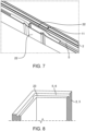
- Fig. 7 shows a perspective view of a housing part 2 in the overlap area 11 of the groove 5, with walls 22 provided to facilitate the insertion of the sealing profile 4.
- the walls 22 can also make it more difficult for the sealing profile 4 to undesirably escape from the groove 5 in the overlap area 11.
- Fig. 8 shows a perspective view of a housing part 2 or 3 in the region of a curve of the groove 5 or 6 with a wall 23 arranged inside the groove 5 or 6 for facilitating the insertion of the sealing profile 4 (not shown).
- a wall 23 can be particularly helpful for automated insertion of the sealing profile 4.
- the inventive design of the housing 1 facilitates the arrangement of a sealing profile 4 and thus reduces the effort and costs involved in assembling the housing 1 for electronic components, in particular photovoltaic inverters, which must meet certain protection classes (e.g. IP65).
- IP65 certain protection classes
Landscapes
- Engineering & Computer Science (AREA)
- Microelectronics & Electronic Packaging (AREA)
- Casings For Electric Apparatus (AREA)
Abstract
Die Erfindung betrifft ein Gehäuse (1) für elektronische Komponenten, insbesondere Photovoltaik-Wechselrichtergehäuse, mit zumindest zwei miteinander verbindbaren Gehäuseteilen (2, 3) und einem Dichtungsprofil (4) zur Abdichtung des Innenraums (I) des Gehäuses (1) gegenüber dem Außenraum (A) des Gehäuses (1), welches Dichtungsprofil (4) in zumindest einer Nut (5, 6) zumindest eines Gehäuseteils (2, 3) angeordnet ist. Erfindungsgemäß ist die zumindest eine Nut (5, 6) in zumindest einem Gehäuseteilen (2, 3) in Form einer offenen Strecke ausgebildet, wobei der Anfang (7, 9) und das Ende (8, 10) der zumindest einen Nut (5, 6) in einem Überlappungsbereich (11) mit einer vorbestimmten Länge (lU) nebeneinander angeordnet ist, und das Dichtungsprofil (4) vorzugsweise klebefrei in der zumindest einen Nut (5, 6) angeordnet ist, und das Dichtungsprofil (4) zumindest über einen Teil der vorbestimmten Länge (lU) des Überlappungsbereichs (11) berührend nebeneinander angeordnet ist.
Description
- Die Erfindung betrifft ein Gehäuse für elektronische Komponenten, insbesondere Photovoltaik-Wechselrichtergehäuse, mit zumindest zwei miteinander verbindbaren Gehäuseteilen und einem Dichtungsprofil zur Abdichtung des Innenraums des Gehäuses gegenüber dem Außenraum des Gehäuses, welches Dichtungsprofil in zumindest einer Nut zumindest eines Gehäuseteils angeordnet ist.
- Grundsätzlich sind beliebige Gehäuse für elektronische Komponenten umfasst, welche eine Dichtung aufweisen, um den Innenraum des Gehäuses, also die entsprechende Elektronik, vor Einflüssen des Außenraums zu schützen. Im Allgemeinen besteht das Gehäuse aus zwei Gehäuseteilen, einem wannenförmigen Gehäuseteil und einem Deckel. Es sind verschiedenste Formen an Gehäusen denkbar, welche auch aus mehr als zwei Gehäuseteilen bestehen können. In erster Linie soll ein Eintritt von Staub in den Innenraum weitestgehend verhindert werden, um eine möglichst hohe Lebensdauer der jeweiligen elektronischen Komponenten gewährleisten zu können. Für manche Geräte, insbesondere solche, die im Freien aufgestellt werden müssen, können auch höhere Anforderungen gelten. Beispielsweise werden Photovoltaik-Wechselrichter häufig im Au-βenbereich platziert, wo sie teilweise enormen Temperaturschwankungen und anderen Umwelteinflüssen, wie zum Beispiel Regen und Stürmen, ausgesetzt sind. Aus diesem Grund müssen manche elektrischen Geräte bestimmte Normen oder Schutzklassen erfüllen. Beispielsweise gilt im Europäischen Raum für Photovoltaik-Wechselrichter häufig die Schutzklasse IP65 der Internationalen Elektrotechnischen Kommission (IEC 60529). Diese Schutzklasse fordert die höchste Klasse gegen den Eintritt von festen Fremdkörpern und einen hohen Schutz gegen einen leichten Druckwasserstrahl und andere Flüssigkeiten, also Staub- und Wasserdichtheit.
- Zum Schutz elektronischer Gehäuse vor Staub und Wasser werden häufig Dichtungen zwischen den Gehäuseteilen des Gehäuses eingelegt. Auch bei Gehäusen von Photovoltaik-Wechselrichtern werden neben aufgesprühten Schaumdichtungen hauptsächlich Dichtungsprofile, insbesondere Hohlkammerprofildichtungen, verwendet, um den Innenraum des Gehäuses gegenüber dem Außenraum abzudichten. Dichtungsprofile haben gegenüber Schaumdichtungen den Vorteil einer Tauschmöglichkeit im Servicefall und einer hohen Zulässigkeit von Toleranzen zwischen den Komponenten. Damit solche Dichtungsprofile für Schutzklassen, beispielsweise die oben erwähnte IP65, geeignet sind, müssen diese in einem Ring angeordnet werden, dessen Enden verklebt werden. Im Falle einer Hohlkammerprofildichtung muss diese auch noch an der Innenseite des Gehäuses gelocht werden, um einen Druckausgleich zwischen der Hohlkammer und dem Innenraum des Gehäuses zu ermöglichen. Dementsprechend müssen die Dichtungsprofile in relativ genauer Länge vorliegen und die Enden exakt senkrecht geschnitten und miteinander verklebt werden. Nachträglich wird die Verklebung manuell geschliffen, damit das Dichtungsprofil im Bereich der Verklebung dicht an der zumindest einen Nut zumindest eines Gehäuseteils anliegt. Diese Arbeiten sind besonders arbeits- und kostenintensiv. Eine Automatisierung ist mit solchen Dichtungen schwer bzw. nicht umsetzbar.
- Beispielsweise beschreibt die
CN 21937229 U ein Gehäuse eines Photovoltaik-Wechselrichters, bei dem ein umlaufendes Dichtungsprofil in einer umlaufenden Nut eines Gehäuseteils angeordnet ist. - Aus der
CN 217336182 U ist ebenfalls ein Gehäuse mit einem umlaufenden Dichtungsprofil bekannt geworden, mit einem speziellen Verlauf des Dichtungsprofil im Bereich der Bohrungen für die Anordnung von Schrauben zur Verbindung der Gehäuseteile. Über entsprechende konstruktive Elemente an den Gehäuseteilen wird das Dichtungsprofil in der gewünschten Position gehalten. - Die Aufgabe der vorliegenden Erfindung besteht in der Schaffung eines Gehäuses für elektronische Komponenten, insbesondere Photovoltaik-Wechselrichter, welches ausreichend dicht und gegebenenfalls entsprechend bestimmten Schutzklassen ausgeführt ist. Die Dichtungen sollen möglichst rasch und einfach, allenfalls auch automatisierbar, in die Gehäuseteile eingelegt werden können. Nachteile bekannter Gehäuse, insbesondere Photovoltaik-Wechselrichtergehäuse, sollen vermieden oder zumindest reduziert werden.
- Gelöst wird die erfindungsgemäße Aufgabe durch ein oben genanntes Gehäuse, bei dem die zumindest eine Nut in zumindest einem Gehäuseteil in Form einer offenen Strecke ausgebildet ist, wobei der Anfang und das Ende der zumindest einen Nut in einem Überlappungsbereich mit einer vorbestimmten Länge nebeneinander angeordnet ist, und das Dichtungsprofil vorzugsweise klebefrei in der zumindest einen Nut und zumindest über einen Teil der vorbestimmten Länge des Überlappungsbereichs berührend nebeneinander angeordnet ist. Durch die überlappende Anordnung der zumindest einen Nut zumindest eines Gehäuseteils und somit der überlappenden Anordnung des Dichtungsprofils in der zumindest einen Nut ist kein umlaufendes, an den Enden in aufwendiger Weise verbundenes bzw. verklebtes Dichtungsprofil mehr notwendig und die entsprechenden Arbeitsschritte für die Bearbeitung und Verbindung der Ende des Dichtungsprofils und allfällige Nachbearbeitung der Verbindungsstelle können entfallen. Dennoch wird durch die Berührung der Enden des Dichtungsprofils zumindest über einen Teil der vorbestimmten Länge des Überlappungsbereichs eine Abdichtung des Innenraums des Gehäuses gegenüber dem Außenraum bei geschlossenem Gehäuse erzielt. Je nach Schutzklasse müssen gegebenenfalls noch weitere Maßnahmen zur Erfüllung gesetzt werden, welche weiter unten optional beschrieben werden. Für die sichere Anordnung des Dichtungsprofils in zumindest einem Gehäuseteil des Gehäuses ist zumindest eine Nut in einem Gehäuseteil notwendig. Der zumindest eine weitere Gehäuseteil kann auch ohne Nut entsprechend gestaltet werden, solange sichergestellt wird, dass bei verbundenen Gehäuseteilen und geschlossenem Gehäuse das Dichtungsprofil eng an den Gehäuseteilen anliegt. Es können aber auch beide oder mehrere Gehäuseteile des Gehäuses mit entsprechenden gegenüberliegenden Nuten versehen sein, sodass das Dichtungsprofil von den gegenüberliegenden Nuten der Gehäuseteile umfasst wird. Die Konstruktion des Gehäuses mit Anordnung der zumindest einen Nut in zumindest einem Gehäuseteil und entsprechend des Dichtungsprofils in Form einer offenen Strecke anstelle eines in sich geschlossenen Rings bringt eine Arbeitserleichterung mit sich und ermöglicht zudem eine automatisierte Anordnung des Dichtungsprofils an einem Gehäuseteil und gegebenenfalls auch die automatisierte Verbindung aller Gehäuseteile und somit das Verschließen des Gehäuses. Dadurch können weitere Kosten eingespart und Arbeitsschritte beschleunigt werden. Vorzugsweise erfolgt die Anordnung des Dichtungsprofils klebefrei, wodurch das Dichtungsprofil ohne großen Aufwand entnommen und beispielsweise getauscht werden kann. Ein weiterer Vorteil des offenen Dichtungsprofils ist eine höhere Toleranzzulässigkeit. Während beim Stand der Technik zu kurze in sich geschlossene Ringe des Dichtungsprofils nicht verwendet werden konnten, da sie nicht in die vorgegebene Nut passen, lässt die vorliegend Konstruktion des Gehäuses größere Toleranzen zu. Wenn das Dichtungsprofil zu kurz abgeschnitten wurde, würde nur der Bereich, in dem sich die Enden des Dichtungsprofils im Überlappungsbereich berühren, etwas kürzer ausfallen. Die Dichtheit des Gehäuses wäre aber dennoch gewährleistet, wenn die Länge der Berührung nicht unter ein bestimmtes Maß fällt. Unter Umständen kann es für manche Anwendungen dennoch von Vorteil oder sogar gefordert sein, die Dichtung zumindest stellenweise mit einem Gehäuseteil zu verkleben. Das Dichtungsprofil muss natürlich aus elastischem Material gebildet sein.
- Vorteilhafterweise ist der Überlappungsbereich der Nuten und des Dichtungsprofils im Wesentlichen parallel zu einer Außenseite des Gehäuses im Überlappungsbereich angeordnet. Dadurch wird nur ein minimaler Innenraum des Gehäuses durch den Überlappungsbereich eingenommen.
- Alternativ dazu kann der Überlappungsbereich auch im Wesentlichen senkrecht zu einer Außenseite des Gehäuses im Überlappungsbereich angeordnet sein. In diesem Fall wird zwar mehr Innenraum des Gehäuses durch den Überlappungsbereich eingenommen, dafür sind beide Enden des Dichtungsprofils nach Innen gerichtet, was für manche Anwendungen vorteilhaft sein kann.
- Die vorbestimmte Länge des Überlappungsbereichs kann beispielsweise zwischen 10 mm und 80 mm betragen. Die Länge des Überlappungsbereichs soll jedenfalls gewährleisten, dass die Enden des Dichtungsprofils eine gewisse Mindestlänge nebeneinander berührend angeordnet sind, sodass zwischen den Dichtungsprofilen kein Staub oder keine Feuchtigkeit vom Außenraum des Gehäuses in den Innenraum eindringen kann und somit die geforderte Dichtheit erfüllt wird.
- Gemäß einem weiteren Merkmal der Erfindung ist das Dichtungsprofil durch eine Hohlkammerprofildichtung mit zumindest einer in Längsrichtung durchgehenden Hohlkammer gebildet. Solche Hohlkammerprofile werden häufig für die Abdichtung von Gehäusen eingesetzt. Da das Hohlkammerprofil zumindest an einem Ende offen bleibt, ist über das offene Ende ein Druckausgleich mit der Umgebung möglich. Somit kann der bei in sich geschlossenen Hohlkammerprofildichtungen notwendige Schritt des Lochens der Hohlkammerprofildichtung entfallen. Das erleichtert den Zusammenbau des Gehäuses und senkt somit die Gesamtkosten noch weiter.
- Wenn an der gegenüberliegenden Seite der zumindest einen Hohlkammer der Hohlkammerprofildichtung ein Klemmprofil angeordnet ist, lässt sich ein solches Dichtungsprofil besonders einfach und rasch in eine Nut eines Gehäuseteils des Gehäuses einlegen. Durch das geeignet gestaltete Klemmprofil, beispielsweise in Form mehrerer beidseitig abstehender Stege, hält die Hohlkammerprofildichtung automatisch und ohne Notwendigkeit eines Klebstoffs ausreichend fest in der Nut eines Gehäuseteils.
- Der Anfang der Hohlkammerprofildichtung im Überlappungsbereich ist idealerweise zum Außenraum des Gehäuses hin angeordnet und verschlossen und das Ende der Hohlkammerprofildichtung im Überlappungsbereich zum Innenraum des Gehäuses hin angeordnet und offen. Durch den verschlossenen Anfang der Hohlkammerprofildichtung wird das Eindringen von Feuchtigkeit von Außen in die zumindest eine Hohlkammer der Hohlkammerprofildichtung verhindert. Andererseits ermöglicht das in den Innenraum des Gehäuses weisende offene Ende der Hohlkammerprofildichtung einen Druckausgleich zwischen der Hohlkammer und dem Innenraum des Gehäuses. Somit kann die bereits oben beschriebene Lochung der Hohlkammerprofildichtung für den Druckausgleich unterbleiben. Insbesondere bei sehr starken Temperaturschwankungen in der Umgebung des Gehäuses kann der Druckausgleich besonders wichtig sein. Um einen Druckausgleich auch zwischen dem Innenraum und dem Außenraum des geschlossenen Gehäuses zu ermöglichen, können zusätzliche Druckausgleichsventile am Gehäuse angeordnet sein.
- Dabei ist der Anfang der Hohlkammerprofildichtung vorzugsweise durch Klemmung verschlossen. Eine solche Klemmung kann besonders rasch und einfach vorgenommen werden und erfordert im Wesentlichen keine vorherige Bearbeitung der Hohlkammerprofildichtung.
- Diese Klemmung des Anfangs der Hohlkammerprofildichtung kann in besonders geeigneter Weise durch einen Fortsatz in der Nut eines Gehäuseteils und durch ein Gegenstück am anderen Gehäuseteil gebildet sein. Somit wird der Anfang der Hohlkammerprofildichtung automatisch beim Befestigen der Gehäuseteile bzw. beim Schließen des Gehäuses geklemmt und somit verschlossen. Notwendig ist nur eine entsprechende Konstruktion des erwähnten Fortsatzes und des Gegenstücks am anderen Gehäuseteil. Idealerweise wird der Fortsatz und das Gegenstück gleich in den jeweiligen Gehäuseteilen integriert und beim Herstellungsvorgang (beispielsweise durch ein Spritzgießverfahren oder Gießverfahren) berücksichtigt.
- Bei geschlossenem Gehäuse beträgt der Abstand zwischen dem oben genannten Fortsatz und dem Gegenstück zwischen 20% und 50% der Höhe der Hohlkammerprofildichtung. Dieser Grad an Klemmung reicht üblicherweise für einen sicheren Verschluss des Anfangs der Hohlkammerprofildichtung und der darin angeordneten zumindest einen Hohlkammer. Unter der Höhe der Hohlkammerprofildichtung wird die Höhe des Querschnitts der Hohlkammerprofildichtung ohne allfälliges Klemmprofil verstanden.
- Wenn zwischen den Nuten eines Gehäuseteils im Überlappungsbereich zumindest ein Druckelement, insbesondere ein Drucksteg, angeordnet ist, können der Anfang und das Ende des Dichtungsprofils im Überlappungsbereich etwas gequetscht und damit aneinandergepresst werden. Dies gewährleistet eine gute Abdichtung des Raumes zwischen den einander überlappenden Enden des Dichtungsprofils im Überlappungsbereich.
- Wenn der Anfang der Hohlkammerprofildichtung stufenförmig geschnitten ist, sodass der Teil der Hohlkammerpofildichtung mit der zumindest einen Hohlkammer über das Klemmprofil hervorsteht, kann der Bereich der Hohlkammerprofildichtung, in der die zumindest eine Hohlkammer angeordnet ist, durch die oben beschriebenen Maßnahmen optimal geklemmt und somit die zumindest eine Hohlkammer verschlossen werden. Das stufenförmige Schneiden der Hohlkammerprofildichtung erfolgt vorzugsweise auch automatisch. Das Ende des Hohlkammerprofils kann ebenfalls mit dem stufenförmigen Schnitt versehen bleiben, auch wenn dort eine Klemmung des Endes der Hohlkammerprofildichtung nicht notwendig ist. Es kann aber ein Verschnitt vermieden und ein weiterer Arbeitsschritt bei dem das Ende der Hohlkammerprofildichtung eben abgeschnitten würde, entfallen.
- Im Bereich des Anfangs einer Nut eines Gehäuseteils kann eine Markierung angeordnet sein, welche die Stelle kennzeichnet, an der das Dichtungsprofil eingelegt werden soll. Die Markierung, welche durch eine Kerbe oder einen vorzugsweise farbigen Strich oder dgl. gebildet sein kann, zeigt dem Monteur beim manuellen Einlegen des Dichtungsprofils somit an, wo der Beginn des Dichtungsprofils platziert werden soll, bevor das Dichtungsprofil in die Nut eingelegt wird, bis das Ende des Dichtungsprofils wieder an der gewünschten Stelle im Überlappungsbereich endet. Natürlich kann die Markierung auch für Manipulatoren oder Roboter ausgelegt sein und eine Unterstützung bieten.
- Wenn die zumindest eine Nut zumindest eines Gehäuseteils im Überlappungsbereich außen durch eine Wand begrenzt ist, kann das Einlegen des Dichtungsprofils erleichtert und ein unerwünschtes Austreten des Dichtungsprofils aus der Nut im Überlappungsbereich erschwert werden. Insbesondere beim automatischen Einlegen des Dichtungsprofils mit entsprechenden Manipulatoren oder Robotern kann eine solche Wand hilfreich sein.
- Das Einlegen des Dichtungsprofils, insbesondere das automatisierte Einlegen, kann weiter unterstützt werden, wenn die zumindest eine Nut zumindest eines Gehäuseteils an der Innenseite einer Kurve durch eine Wand begrenzt ist. Die Wand bildet demnach in den Kurven eine Art Führung für das Dichtungsprofil beim Einlegevorgang.
- Bei vertikaler Anordnung des Gehäuses in einer Gebrauchslage ist es von Vorteil, wenn der Anfang der Hohlkammerprofildichtung nach unten weisend angeordnet ist. Dies stellt sicher, dass Feuchtigkeit schwerkraftbedingt nicht in eine Hohlkammer der Hohlkammerprofildichtung eindringen kann, wenn diese beispielsweise durch unzureichende Klemmung nicht vollständig verschlossen ist.
- Das Dichtungsprofil ist vorzugsweise aus Kunststoff, insbesondere aus Silikon, gebildet. Vorausgesetzt wird eine gewisse Elastizität des Materials und eine hohe Lebensdauer. Insbesondere beim Einsatz in Photovoltaik-Wechselrichtergehäusen ist auch eine hohe Temperaturbeständigkeit gefordert. Neben Kunststoffen kommen für das Dichtungsprofil auch natürliche Materialien, wie zum Beispiel Kautschuk, in Frage.
- Wie bereits erwähnt, ist es von Vorteil, wenn das Dichtungsprofil automatisiert in eine Nut eines Gehäuseteils einlegbar ist, da somit Zeit und Kosten bei der Zusammenstellung des Gehäuses gespart werden kann.
- Die zumindest zwei Gehäuseteile können in herkömmlicher Weise durch Schrauben oder Schnellverschlüsse miteinander verbindbar sein. Die Schrauben, Schnellverschlüsse oder anderen Befestigungselemente sollen eine möglichst rasche und sichere Verbindung der Gehäuseteile und somit ein Schließen des Gehäuses ermöglichen. Um sicherzustellen, dass die Befestigungselemente ausreichend fest sitzen, können Rastelemente vorgesehen werden, welche den ordnungsgemäßen Verschluss haptisch und allenfalls auch akustisch signalisieren.
- Zumindest ein Gehäuseteil kann aus Metall, insbesondere aus Aluminium oder einer Aluminiumlegierung, oder aus Kunststoff, insbesondere aus Thermoplasten, bestehen. Beispielsweise kann ein Gehäuseteil aus Polyamid oder Polycarbonat hergestellt werden.
- Die vorliegende Erfindung wird anhand der beigefügten Zeichnungen näher erläutert. Darin zeigen:
- Fig. 1
- eine erste Ausführungsform eines erfindungsgemäßen Gehäuses mit geöffneten Gehäuseteilen;
- Fig. 2
- eine zweite Ausführungsform eines erfindungsgemäßen Gehäuses mit geöffneten Gehäuseteilen;
- Fig. 3A und 3B
- eine Stirnansicht und ein seitliches Schnittbild des Endes einer üblichen Hohlkammerprofildichtung;
- Fig. 4A und 4B
- Detailansichten auf die Nuten der beiden Gehäuseteile im Überlappungsbereich;
- Fig. 5
- ein Schnittbild durch einen Teil eines zusammengebauten Gehäuses im Überlappungsbereich entlang der Schnittlinie V - V in
Figur 4A ; - Fig. 6
- ein Schnittbild durch einen Teil eines zusammengebauten Gehäuses im Überlappungsbereich entlang der Schnittlinie VI - VI in
Figur 4A ; - Fig. 7
- eine perspektivische Ansicht auf einen Gehäuseteil im Überlappungsbereich der Nut, wobei Wände zum erleichterten Einlegen des Dichtungsprofils vorgesehen sind; und
- Fig. 8
- eine perspektivische Ansicht auf einen Gehäuseteil im Bereich einer Kurve der Nut mit einer innenseitig der Nut angeordneten Wand zum erleichterten Einlegen des Dichtungsprofils.
-
Fig. 1 zeigt eine erste Ausführungsform eines erfindungsgemäßen Gehäuses 1 mit zwei geöffneten Gehäuseteilen 2, 3. Das Gehäuse 1 dient der Aufnahme und dem Schutz elektronischer Komponenten, wie zum Beispiel einem Photovoltaik-Wechselrichter (nicht dargestellt). Die beiden Gehäuseteile 2, 3 können in üblicher Weise mit entsprechenden Befestigungselementen, wie zum Beispiel Schrauben oder Schnellverschlüssen oder dgl. (nicht dargestellt) miteinander verbunden werden. Damit der Innenraum I des Gehäuses 1 in geschlossenem Zustand gegenüber dem Außenraum A abgedichtet um die darin angeordneten elektronischen Komponenten vor Umwelteinflüssen zu schützen, wird ein Dichtungsprofil 4 aus elastischem Material zwischen den beiden Gehäuseteilen 2, 3 angeordnet. In zumindest einem oder beiden Gehäuseteil(en) 2, 3 ist eine Nut 5, 6 angeordnet, in welche das Dichtungsprofil 4 bei verbundenen Gehäuseteilen 2, 3 eingelegt ist. Beim Stand der Technik handelt es sich meist um ein umlaufendes, also in sich geschlossenes Dichtungsprofil 4 (nicht dargestellt). Die Anfertigung und Anordnung eines solchen umlaufenden Dichtungsprofils 4 ist mit entsprechendem Aufwand verbunden. - Beim erfindungsgemäßen Gehäuse 1 ist die zumindest eine Nut 5, 6 in zumindest einem Gehäuseteil 2, 3 in Form einer offenen Strecke ausgebildet, also nicht in sich geschlossen. Im dargestellten Ausführungsbeispiel ist in jedem Gehäuseteil 2, 3 eine Nut 5, 6 vorgesehen, welche im zusammengesetzten Zustand der Gehäuseteile 2, 3 übereinstimmen. Es ist auch ein Gehäuse 1 möglich, bei dem nur in einem Gehäuseteil 2 oder 3 eine Nut 5 oder 6 angeordnet ist und das andere Gehäuseteil 3 oder 2 eben ausgeführt wird. Beim geschlossenen Gehäuse 1 ist das Dichtungsprofil 4 dann in beiden Nuten 5, 6 eingelegt und dichtet somit den Innenraum I des Gehäuses 1 gegenüber dem Außenraum A entsprechend ab. Der Anfang 7 und das Ende 8 der Nut 5 des Gehäuseteils 2 sowie der Anfang 9 und das Ende 10 der Nut 6 des Gehäuseteils 3 ist in einem Überlappungsbereich 11 mit einer vorbestimmten Länge lU nebeneinander angeordnet. Somit kann das offene Dichtungsprofil 4 in die Nut 5 oder 6 des Gehäuseteils 2 oder 3 eingelegt werden, ohne dass ein geschlossenes Dichtungsprofil 4 angefertigt werden muss. Die erforderliche Abdichtung des Innenraums I des geschlossenen Gehäuses 1 gegenüber dem Außenraum A wird dadurch gewährleistet, dass das Dichtungsprofil 4 zumindest über einen Teil der vorbestimmten Länge lU des Überlappungsbereichs 11 berührend nebeneinander angeordnet ist. Das Dichtungsprofil 4 wird vorzugsweise klebefrei in der zumindest einen Nut 5, 6 angeordnet, sodass es einfach entfernt und beispielsweise ausgetauscht werden kann. Die Form der Nut 5, 6 und der Querschnitt des Dichtungsprofil 4 wird entsprechend aufeinander abgestimmt.
- Im dargestellten Ausführungsbeispiel ist der Überlappungsbereich 11 im Wesentlichen parallel zu einer Außenseite des Gehäuses 1 im Überlappungsbereich 11 angeordnet. Dadurch wird der Innenraum I des Gehäuses 1 durch den Überlappungsbereich 11 kaum eingeschränkt oder verkleinert. Der Überlappungsbereich 11 kann somit am Rand der Gehäuseteile 2, 3 untergebracht werden. Der Rand der Gehäuseteile 2, 3 kann zumindest im Überlappungsbereich 11 allenfalls etwas breiter ausgeführt werden (nicht dargestellt).
-
Fig. 2 zeigt eine zweite Ausführungsform eines erfindungsgemäßen Gehäuses 1 mit geöffneten Gehäuseteilen 2, 3. Bei dieser Variante ist der Überlappungsbereich 11 im Wesentlichen senkrecht zu einer Außenseite des Gehäuses 1 im Überlappungsbereich 11 angeordnet. In diesem Fall wird zwar mehr Innenraum I des Gehäuses 1 durch den Überlappungsbereich 11 eingenommen, dafür ist der Anfang 7, 9 und das Ende 8, 10 der Nuten 5, 6 der Gehäuseteile 2, 3 und somit die Enden des Dichtungsprofils 4 beim geschlossenen Gehäuse 1 (nicht dargestellt) zum Innenraum I hin angeordnet, was für manche Anwendungen vorteilhaft sein kann. -
Fig. 3A zeigt eine Stirnansicht undFigur 3B ein seitliches Schnittbild entlang der Schnittlinie III-III inFig. 3A durch das Ende einer üblichen Hohlkammerprofildichtung 12 als Dichtungsprofil 4. Die Hohlkammerprofildichtung 12 weist eine in Längsrichtung durchgehende Hohlkammer 13 auf. An der gegenüberliegenden Seite der Hohlkammer 13 der Hohlkammerprofildichtung 12 ist ein Klemmprofil 14 angeordnet. Das Klemmprofil 14 kann verschiedenartig gestaltet sein, um einen guten Halt der Hohlkammerprofildichtung 12 in einer geeigneten Nut (nicht dargestellt) auch ohne Notwendigkeit eines Klebstoffs gewährleisten zu können. Beispielsweise können mehrere (hier drei) beidseitig abstehende Stege vorgesehen sein, sodass ein Tannenbaum-artiges Klemmprofil 14 entsteht. - Wie in
Fig. 3B ersichtlich, ist der Anfang 15 der Hohlkammerprofildichtung 12 stufenförmig geschnitten, sodass der Teil der Hohlkammerpofildichtung 12 mit der Hohlkammer 13 über das Klemmprofil 14 hervorsteht. Dadurch kann der Bereich der Hohlkammerprofildichtung 12, in der die Hohlkammer 13 angeordnet ist, optimal geklemmt werden. Bei der Klemmung des Anfangs 15 der Hohlkammerprofildichtung 12 wird die Höhe hH der Hohlkammerprofildichtung 12 ohne Klemmprofil 14 entsprechend verringert, sodass die Hohlkammer 13 verschlossen wird. Die Klemmung der Hohlkammerprofildichtung 12 wird anhand derFiguren 4A, 4B und5 noch detaillierter erklärt. -
Fig. 4A und 4B zeigen Detailansichten auf die Nuten 5, 6 der beiden Gehäuseteile 2, 3 im Überlappungsbereich 11.Fig. 4A zeigt die Nut 5 des Gehäuseteils 2 undFig. 4B die Nut 6 im Gehäuseteil 3 im Überlappungsbereich 11. Dementsprechend ist der Anfang 7 und das Ende 8 der Nut 5 und der Anfang 9 und das Ende 10 der Nut 6 im Überlappungsbereich 11 mit der vorbestimmten Länge lU nebeneinander angeordnet. Das Dichtungsprofil 4 ist zumindest über einen Teil der vorbestimmten Länge lU des Überlappungsbereichs 11 berührend nebeneinander angeordnet (sieheFig. 6 ). Zum Klemmen des Anfangs 15 einer Hohlkammerprofildichtung 12 ist in der Nut 5 des Gehäuseteils 2 ein Fortsatz 17 angeordnet und am anderen Gehäuseteil 3 ein entsprechendes Gegenstück 18. Im SchnittbildFig. 5 entlang der Schnittlinie V - V inFig. 4A ist die Klemmung der Hohlkammerprofildichtung 12 zwischen dem Fortsatz 17 und dem Gegenstück 18 deutlicher zu erkennen. - Weiters können zwischen den Nuten 6 eines Gehäuseteils 3 im Überlappungsbereich 11 Druckelemente 19, insbesondere Druckstege 20, angeordnet sein, durch welche der Anfang und das Ende des Dichtungsprofils 4 bzw. der Hohlkammerprofildichtung 12 im Überlappungsbereich 11 etwas gequetscht und damit aneinandergepresst werden. Dies gewährleistet eine gute Abdichtung des Raumes zwischen den überlappenden Enden des Dichtungsprofils 4 im Überlappungsbereich 11 (siehe Schnittbild
Fig. 6 entlang der Schnittlinie VI - VI inFig. 4A ). - Im Bereich des Anfangs 7 der Nut 5 des Gehäuseteils 2 kann eine Markierung 21 angeordnet sein. Eine solche Markierung 21, welche durch eine Kerbe oder einen vorzugsweise farbigen Strich oder dgl. gebildet sein kann, wird dem Monteur beim manuellen Einlegen des Dichtungsprofils 4 angezeigt, wo der Beginn des Dichtungsprofils 4 platziert werden soll, bevor das Dichtungsprofil 4 in die Nut 5 eingelegt wird. Die Markierung 21 kann aber auch für Roboter ausgelegt sein und beispielsweise über Kameras erfasst werden.
-
Fig. 7 zeigt eine perspektivische Ansicht auf einen Gehäuseteil 2 im Überlappungsbereich 11 der Nut 5, wobei Wände 22 zum erleichterten Einlegen des Dichtungsprofils 4 vorgesehen sind. Durch die Wände 22 kann auch ein unerwünschtes Austreten des Dichtungsprofils 4 aus der Nut 5 im Überlappungsbereich 11 erschwert werden. -
Fig. 8 zeigt eine perspektivische Ansicht auf einen Gehäuseteil 2 oder 3 im Bereich einer Kurve der Nut 5 oder 6 mit einer innenseitig der Nut 5 oder 6 angeordneten Wand 23 zum erleichterten Einlegen des Dichtungsprofils 4 (nicht dargestellt). Insbesondere bei einem automatisierten Einlegen des Dichtungsprofils 4 kann eine solche Wand 23 hilfreich sein. - Die erfindungsgemäße Gestaltung des Gehäuses 1 erleichtert die Anordnung eines Dichtungsprofils 4 und senkt somit den Aufwand und die Kosten beim Zusammenbau des Gehäuses 1 für elektronische Komponenten, insbesondere von Photovoltaik-Wechselrichtern, welche bestimmte Schutzklassen (z.B. IP65) erfüllen müssen.
Claims (15)
- Gehäuse (1) für elektronische Komponenten, insbesondere Photovoltaik-Wechselrichtergehäuse, mit zumindest zwei miteinander verbindbaren Gehäuseteilen (2, 3) und einem Dichtungsprofil (4) zur Abdichtung des Innenraums (I) des Gehäuses (1) gegenüber dem Außenraum (A) des Gehäuses (1), welches Dichtungsprofil (4) in zumindest einer Nut (5, 6) zumindest eines Gehäuseteils (2, 3) angeordnet ist, dadurch gekennzeichnet, dass die zumindest eine Nut (5, 6) in zumindest einem Gehäuseteil (2, 3) in Form einer offenen Strecke ausgebildet ist, wobei der Anfang (7, 9) und das Ende (8, 10) der zumindest einen Nut (5, 6) in einem Überlappungsbereich (11) mit einer vorbestimmten Länge (lU) nebeneinander angeordnet ist, und das Dichtungsprofil (4) vorzugsweise klebefrei in der zumindest einen Nut (5, 6) und zumindest über einen Teil der vorbestimmten Länge (lU) des Überlappungsbereichs (11) berührend nebeneinander angeordnet ist.
- Gehäuse (1) nach Anspruch 1, dadurch gekennzeichnet, dass der Überlappungsbereich (11) im Wesentlichen parallel zu einer Außenseite des Gehäuses (1) im Überlappungsbereich (11) angeordnet ist.
- Gehäuse (1) nach Anspruch 1, dadurch gekennzeichnet, dass der Überlappungsbereich (11) im Wesentlichen senkrecht zu einer Außenseite des Gehäuses (1) im Überlappungsbereich (11) angeordnet ist.
- Gehäuse (1) nach einem der Ansprüche 1 bis 3, dadurch gekennzeichnet, dass das Dichtungsprofil (4) durch eine Hohlkammerprofildichtung (12) mit zumindest einer in Längsrichtung durchgehenden Hohlkammer (13) gebildet ist.
- Gehäuse (1) nach Anspruch 4, dadurch gekennzeichnet, dass an der gegenüberliegenden Seite der zumindest einen Hohlkammer (13) der Hohlkammerprofildichtung (12) ein Klemmprofil (14) angeordnet ist.
- Gehäuse (1) nach Anspruch 4 oder 5, dadurch gekennzeichnet, dass der Anfang (15) der Hohlkammerprofildichtung (12) im Überlappungsbereich (11) zum Außenraum (A) des Gehäuses (1) hin angeordnet und verschlossen ist und das Ende (16) der Hohlkammerprofildichtung (12) im Überlappungsbereich (11) zum Innenraum (I) des Gehäuses (1) hin angeordnet und offen ist.
- Gehäuse (1) nach Anspruch 6, dadurch gekennzeichnet, dass der Anfang (15) der Hohlkammerprofildichtung (12) durch Klemmung verschlossen ist.
- Gehäuse (1) nach Anspruch 7, dadurch gekennzeichnet, dass die Klemmung des Anfangs (15) der Hohlkammerprofildichtung (12) durch einen Fortsatz (17) in einer Nut (5, 6) eines Gehäuseteils (2, 3) und durch ein Gegenstück (18) am anderen Gehäuseteil (3, 2) gebildet ist.
- Gehäuse (1) nach einem der Ansprüche 1 bis 8, dadurch gekennzeichnet, dass zwischen den Nuten (5, 6) eines Gehäuseteils (2, 3) im Überlappungsbereich (11) zumindest ein Druckelement (19), insbesondere ein Drucksteg (20), angeordnet ist.
- Gehäuse (1) nach einem der Ansprüche 4 bis 9, dadurch gekennzeichnet, dass der Anfang (15) der Hohlkammerprofildichtung (12) stufenförmig geschnitten ist, sodass der Teil der Hohlkammerpofildichtung (12) mit der zumindest einen Hohlkammer (13) über das Klemmprofil (14) hervorsteht.
- Gehäuse (1) nach einem der Ansprüche 1 bis 10, dadurch gekennzeichnet, dass im Bereich des Anfangs (7, 9) einer Nut (5, 6) eines Gehäuseteils (2, 3) eine Markierung (21) angeordnet ist.
- Gehäuse (1) nach einem der Ansprüche 1 bis 11, dadurch gekennzeichnet, dass die zumindest eine Nut (5, 6) zumindest eines Gehäuseteils (2, 3) im Überlappungsbereich (11) außen durch eine Wand (22) begrenzt ist.
- Gehäuse (1) nach einem der Ansprüche 1 bis 12, dadurch gekennzeichnet, dass die zumindest eine Nut (5, 6) zumindest eines Gehäuseteils (2, 3) an der Innenseite einer Kurve durch eine Wand (23) begrenzt ist.
- Gehäuse (1) nach einem der Ansprüche 4 bis 13, dadurch gekennzeichnet, dass bei vertikaler Anordnung des Gehäuses (1) in einer Gebrauchslage der Anfang (15) der Hohlkammerprofildichtung (12) nach unten weisend angeordnet ist.
- Gehäuse (1) nach einem der Ansprüche 1 bis 14, dadurch gekennzeichnet, dass das Dichtungsprofil (4) automatisiert in eine Nut (5, 6) eines Gehäuseteils (2, 3) einlegbar ist.
Priority Applications (3)
| Application Number | Priority Date | Filing Date | Title |
|---|---|---|---|
| EP23219800.2A EP4576956A1 (de) | 2023-12-22 | 2023-12-22 | Gehäuse für elektronische komponenten |
| EP24833725.5A EP4652812B1 (de) | 2023-12-22 | 2024-12-20 | Gehäuse für elektronische komponenten |
| PCT/EP2024/087837 WO2025133079A1 (de) | 2023-12-22 | 2024-12-20 | Gehäuse für elektronische komponenten |
Applications Claiming Priority (1)
| Application Number | Priority Date | Filing Date | Title |
|---|---|---|---|
| EP23219800.2A EP4576956A1 (de) | 2023-12-22 | 2023-12-22 | Gehäuse für elektronische komponenten |
Publications (1)
| Publication Number | Publication Date |
|---|---|
| EP4576956A1 true EP4576956A1 (de) | 2025-06-25 |
Family
ID=89321820
Family Applications (2)
| Application Number | Title | Priority Date | Filing Date |
|---|---|---|---|
| EP23219800.2A Pending EP4576956A1 (de) | 2023-12-22 | 2023-12-22 | Gehäuse für elektronische komponenten |
| EP24833725.5A Active EP4652812B1 (de) | 2023-12-22 | 2024-12-20 | Gehäuse für elektronische komponenten |
Family Applications After (1)
| Application Number | Title | Priority Date | Filing Date |
|---|---|---|---|
| EP24833725.5A Active EP4652812B1 (de) | 2023-12-22 | 2024-12-20 | Gehäuse für elektronische komponenten |
Country Status (2)
| Country | Link |
|---|---|
| EP (2) | EP4576956A1 (de) |
| WO (1) | WO2025133079A1 (de) |
Citations (8)
| Publication number | Priority date | Publication date | Assignee | Title |
|---|---|---|---|---|
| DE1784276U (de) * | 1958-12-27 | 1959-03-05 | Weyer & Zander K G | Abdichtung fuer gehaeuse elektrischer schaltgeraete u. dgl. |
| EP0278567A2 (de) * | 1987-02-07 | 1988-08-17 | DST Deutsche System-Technik GmbH | Elektromagnetische Dichtungsanordnung |
| JPH06188577A (ja) * | 1992-12-18 | 1994-07-08 | Toshiba Corp | 電子機器筐体における防水構造 |
| CN105485344A (zh) * | 2015-12-18 | 2016-04-13 | 宁波速普电子有限公司 | 一种密封结构 |
| US20170248900A1 (en) * | 2016-02-25 | 2017-08-31 | Fuji Xerox Co., Ltd. | Sealing member and image forming apparatus |
| CN109469730A (zh) * | 2017-09-07 | 2019-03-15 | 瑞典爱立信有限公司 | 用于密封的方法和密封设备 |
| CN114727534A (zh) * | 2022-02-25 | 2022-07-08 | 中航光电科技股份有限公司 | 一种用于电子设备顶部密封的顶部密封装置及其密封件 |
| CN217336182U (zh) | 2022-01-28 | 2022-08-30 | 阳光电源(上海)有限公司 | 一种壳体密封结构及逆变器 |
Family Cites Families (8)
| Publication number | Priority date | Publication date | Assignee | Title |
|---|---|---|---|---|
| DE1784276A1 (de) | 1968-07-25 | 1975-01-09 | Maasen Axel | Hallen-schwimm- und sonnenbaeder mit ebbe und flut, wellen und brandung |
| JP4776787B2 (ja) * | 2001-01-30 | 2011-09-21 | 本田技研工業株式会社 | 燃料電池及びその製造方法 |
| US7341259B1 (en) * | 2002-03-05 | 2008-03-11 | Harman International Industries, Incorporated | Air seal system for loudspeaker |
| JP2004108469A (ja) * | 2002-09-18 | 2004-04-08 | Matsushita Electric Ind Co Ltd | 防水パッキングの取付け構造 |
| US8203084B2 (en) * | 2010-03-16 | 2012-06-19 | Tyco Electronics Corporation | Electrical connector assembly with EMI gasket |
| JP6011392B2 (ja) * | 2013-02-28 | 2016-10-19 | 富士通株式会社 | 防水筺体及び防水筺体の製造方法 |
| TWI652000B (zh) * | 2017-07-27 | 2019-02-21 | 英研智能移動股份有限公司 | 防水外殼 |
| JP7063612B2 (ja) * | 2017-12-27 | 2022-05-09 | 住友理工株式会社 | シール構造およびシール部材 |
-
2023
- 2023-12-22 EP EP23219800.2A patent/EP4576956A1/de active Pending
-
2024
- 2024-12-20 WO PCT/EP2024/087837 patent/WO2025133079A1/de active Pending
- 2024-12-20 EP EP24833725.5A patent/EP4652812B1/de active Active
Patent Citations (8)
| Publication number | Priority date | Publication date | Assignee | Title |
|---|---|---|---|---|
| DE1784276U (de) * | 1958-12-27 | 1959-03-05 | Weyer & Zander K G | Abdichtung fuer gehaeuse elektrischer schaltgeraete u. dgl. |
| EP0278567A2 (de) * | 1987-02-07 | 1988-08-17 | DST Deutsche System-Technik GmbH | Elektromagnetische Dichtungsanordnung |
| JPH06188577A (ja) * | 1992-12-18 | 1994-07-08 | Toshiba Corp | 電子機器筐体における防水構造 |
| CN105485344A (zh) * | 2015-12-18 | 2016-04-13 | 宁波速普电子有限公司 | 一种密封结构 |
| US20170248900A1 (en) * | 2016-02-25 | 2017-08-31 | Fuji Xerox Co., Ltd. | Sealing member and image forming apparatus |
| CN109469730A (zh) * | 2017-09-07 | 2019-03-15 | 瑞典爱立信有限公司 | 用于密封的方法和密封设备 |
| CN217336182U (zh) | 2022-01-28 | 2022-08-30 | 阳光电源(上海)有限公司 | 一种壳体密封结构及逆变器 |
| CN114727534A (zh) * | 2022-02-25 | 2022-07-08 | 中航光电科技股份有限公司 | 一种用于电子设备顶部密封的顶部密封装置及其密封件 |
Also Published As
| Publication number | Publication date |
|---|---|
| EP4652812C0 (de) | 2026-04-08 |
| EP4652812A1 (de) | 2025-11-26 |
| EP4652812B1 (de) | 2026-04-08 |
| WO2025133079A1 (de) | 2025-06-26 |
Similar Documents
| Publication | Publication Date | Title |
|---|---|---|
| EP2240987B1 (de) | Steckvorrichtung | |
| EP3625860A1 (de) | Kabeldurchführung | |
| EP1867375A1 (de) | Filterlüfter mit einer Schnellbefestigungseinrichtung | |
| DE69304731T2 (de) | Fensterkonstruktion | |
| DE3030162C2 (de) | Gehäuse für elektrotechnische Geräte, insbesondere für die elektrische Nachrichtentechnik | |
| EP1750339B1 (de) | Hohlkanalanordnung zur Eckumfahrung | |
| DE10137115A1 (de) | Vorrichtung zum Befestigen eines Sensors | |
| EP4652812B1 (de) | Gehäuse für elektronische komponenten | |
| DE3035183C2 (de) | ||
| DE102019206287B4 (de) | Verschließvorrichtung | |
| DE3703090C2 (de) | ||
| DE4416004C1 (de) | Gehäuse, insbesondere zur Aufnahme elektrischer oder elektronischer Bauteile | |
| DE29504754U1 (de) | Gehäuse mit einer Vorrichtung zur Kabelzugentlastung | |
| DE9102932U1 (de) | System aus stapelbaren Modulgehäusen | |
| DE3103687A1 (de) | Gehaeuse sowie verfahren zur herstellung des gehaeusekoerpers | |
| DE8215892U1 (de) | Dichtelement für eine Schraubverbindung | |
| EP1431113B1 (de) | Formteil zur Halterung und Versteifung eines laschenförmigen Ausschnittteils in einem flächigen Gut | |
| DE202007005423U1 (de) | Dichtungsprofil mit Eckführung | |
| DE9303155U1 (de) | Duschkabine | |
| CH683908A5 (de) | Ausguss, insbesondere für Nachfüllbeutel. | |
| WO2021219315A1 (de) | Elektrisches gerät mit einer dichtvorrichtung | |
| DE202022106552U1 (de) | Werkzeug zum Nacharbeiten und Glätten von Fugen | |
| DE10141543A1 (de) | Einrichtung zum Festlegen von Gegenständen an einem Widerlager | |
| DE8102810U1 (de) | Gehäuse | |
| EP4386996A1 (de) | Anschlusssystem |
Legal Events
| Date | Code | Title | Description |
|---|---|---|---|
| PUAI | Public reference made under article 153(3) epc to a published international application that has entered the european phase |
Free format text: ORIGINAL CODE: 0009012 |
|
| STAA | Information on the status of an ep patent application or granted ep patent |
Free format text: STATUS: THE APPLICATION HAS BEEN PUBLISHED |
|
| AK | Designated contracting states |
Kind code of ref document: A1 Designated state(s): AL AT BE BG CH CY CZ DE DK EE ES FI FR GB GR HR HU IE IS IT LI LT LU LV MC ME MK MT NL NO PL PT RO RS SE SI SK SM TR |
|
| STAA | Information on the status of an ep patent application or granted ep patent |
Free format text: STATUS: THE APPLICATION IS DEEMED TO BE WITHDRAWN |