EP4574192A2 - Respiratorische schnittstelle - Google Patents
Respiratorische schnittstelle Download PDFInfo
- Publication number
- EP4574192A2 EP4574192A2 EP25162160.3A EP25162160A EP4574192A2 EP 4574192 A2 EP4574192 A2 EP 4574192A2 EP 25162160 A EP25162160 A EP 25162160A EP 4574192 A2 EP4574192 A2 EP 4574192A2
- Authority
- EP
- European Patent Office
- Prior art keywords
- seal
- headgear
- mask frame
- seal module
- mask
- Prior art date
- Legal status (The legal status is an assumption and is not a legal conclusion. Google has not performed a legal analysis and makes no representation as to the accuracy of the status listed.)
- Pending
Links
Images







Classifications
-
- A—HUMAN NECESSITIES
- A61—MEDICAL OR VETERINARY SCIENCE; HYGIENE
- A61M—DEVICES FOR INTRODUCING MEDIA INTO, OR ONTO, THE BODY; DEVICES FOR TRANSDUCING BODY MEDIA OR FOR TAKING MEDIA FROM THE BODY; DEVICES FOR PRODUCING OR ENDING SLEEP OR STUPOR
- A61M16/00—Devices for influencing the respiratory system of patients by gas treatment, e.g. ventilators; Tracheal tubes
- A61M16/08—Bellows; Connecting tubes ; Water traps; Patient circuits
- A61M16/0816—Joints or connectors
-
- A—HUMAN NECESSITIES
- A61—MEDICAL OR VETERINARY SCIENCE; HYGIENE
- A61M—DEVICES FOR INTRODUCING MEDIA INTO, OR ONTO, THE BODY; DEVICES FOR TRANSDUCING BODY MEDIA OR FOR TAKING MEDIA FROM THE BODY; DEVICES FOR PRODUCING OR ENDING SLEEP OR STUPOR
- A61M16/00—Devices for influencing the respiratory system of patients by gas treatment, e.g. ventilators; Tracheal tubes
- A61M16/04—Tracheal tubes
- A61M16/0488—Mouthpieces; Means for guiding, securing or introducing the tubes
- A61M16/049—Mouthpieces
- A61M16/0493—Mouthpieces with means for protecting the tube from damage caused by the patient's teeth, e.g. bite block
-
- A—HUMAN NECESSITIES
- A61—MEDICAL OR VETERINARY SCIENCE; HYGIENE
- A61M—DEVICES FOR INTRODUCING MEDIA INTO, OR ONTO, THE BODY; DEVICES FOR TRANSDUCING BODY MEDIA OR FOR TAKING MEDIA FROM THE BODY; DEVICES FOR PRODUCING OR ENDING SLEEP OR STUPOR
- A61M16/00—Devices for influencing the respiratory system of patients by gas treatment, e.g. ventilators; Tracheal tubes
- A61M16/06—Respiratory or anaesthetic masks
- A61M16/0605—Means for improving the adaptation of the mask to the patient
- A61M16/0611—Means for improving the adaptation of the mask to the patient with a gusset portion
-
- A—HUMAN NECESSITIES
- A61—MEDICAL OR VETERINARY SCIENCE; HYGIENE
- A61M—DEVICES FOR INTRODUCING MEDIA INTO, OR ONTO, THE BODY; DEVICES FOR TRANSDUCING BODY MEDIA OR FOR TAKING MEDIA FROM THE BODY; DEVICES FOR PRODUCING OR ENDING SLEEP OR STUPOR
- A61M16/00—Devices for influencing the respiratory system of patients by gas treatment, e.g. ventilators; Tracheal tubes
- A61M16/06—Respiratory or anaesthetic masks
- A61M16/0605—Means for improving the adaptation of the mask to the patient
- A61M16/0616—Means for improving the adaptation of the mask to the patient with face sealing means comprising a flap or membrane projecting inwards, such that sealing increases with increasing inhalation gas pressure
-
- A—HUMAN NECESSITIES
- A61—MEDICAL OR VETERINARY SCIENCE; HYGIENE
- A61M—DEVICES FOR INTRODUCING MEDIA INTO, OR ONTO, THE BODY; DEVICES FOR TRANSDUCING BODY MEDIA OR FOR TAKING MEDIA FROM THE BODY; DEVICES FOR PRODUCING OR ENDING SLEEP OR STUPOR
- A61M16/00—Devices for influencing the respiratory system of patients by gas treatment, e.g. ventilators; Tracheal tubes
- A61M16/06—Respiratory or anaesthetic masks
- A61M16/0666—Nasal cannulas or tubing
-
- A—HUMAN NECESSITIES
- A61—MEDICAL OR VETERINARY SCIENCE; HYGIENE
- A61M—DEVICES FOR INTRODUCING MEDIA INTO, OR ONTO, THE BODY; DEVICES FOR TRANSDUCING BODY MEDIA OR FOR TAKING MEDIA FROM THE BODY; DEVICES FOR PRODUCING OR ENDING SLEEP OR STUPOR
- A61M16/00—Devices for influencing the respiratory system of patients by gas treatment, e.g. ventilators; Tracheal tubes
- A61M16/06—Respiratory or anaesthetic masks
- A61M16/0683—Holding devices therefor
-
- A—HUMAN NECESSITIES
- A61—MEDICAL OR VETERINARY SCIENCE; HYGIENE
- A61M—DEVICES FOR INTRODUCING MEDIA INTO, OR ONTO, THE BODY; DEVICES FOR TRANSDUCING BODY MEDIA OR FOR TAKING MEDIA FROM THE BODY; DEVICES FOR PRODUCING OR ENDING SLEEP OR STUPOR
- A61M16/00—Devices for influencing the respiratory system of patients by gas treatment, e.g. ventilators; Tracheal tubes
- A61M16/08—Bellows; Connecting tubes ; Water traps; Patient circuits
- A61M16/0875—Connecting tubes
-
- A—HUMAN NECESSITIES
- A61—MEDICAL OR VETERINARY SCIENCE; HYGIENE
- A61M—DEVICES FOR INTRODUCING MEDIA INTO, OR ONTO, THE BODY; DEVICES FOR TRANSDUCING BODY MEDIA OR FOR TAKING MEDIA FROM THE BODY; DEVICES FOR PRODUCING OR ENDING SLEEP OR STUPOR
- A61M16/00—Devices for influencing the respiratory system of patients by gas treatment, e.g. ventilators; Tracheal tubes
- A61M16/08—Bellows; Connecting tubes ; Water traps; Patient circuits
- A61M16/0816—Joints or connectors
- A61M16/0825—Joints or connectors with ball-sockets
-
- A—HUMAN NECESSITIES
- A61—MEDICAL OR VETERINARY SCIENCE; HYGIENE
- A61M—DEVICES FOR INTRODUCING MEDIA INTO, OR ONTO, THE BODY; DEVICES FOR TRANSDUCING BODY MEDIA OR FOR TAKING MEDIA FROM THE BODY; DEVICES FOR PRODUCING OR ENDING SLEEP OR STUPOR
- A61M2205/00—General characteristics of the apparatus
- A61M2205/02—General characteristics of the apparatus characterised by a particular materials
- A61M2205/0272—Electro-active or magneto-active materials
-
- A—HUMAN NECESSITIES
- A61—MEDICAL OR VETERINARY SCIENCE; HYGIENE
- A61M—DEVICES FOR INTRODUCING MEDIA INTO, OR ONTO, THE BODY; DEVICES FOR TRANSDUCING BODY MEDIA OR FOR TAKING MEDIA FROM THE BODY; DEVICES FOR PRODUCING OR ENDING SLEEP OR STUPOR
- A61M2205/00—General characteristics of the apparatus
- A61M2205/12—General characteristics of the apparatus with interchangeable cassettes forming partially or totally the fluid circuit
-
- A—HUMAN NECESSITIES
- A61—MEDICAL OR VETERINARY SCIENCE; HYGIENE
- A61M—DEVICES FOR INTRODUCING MEDIA INTO, OR ONTO, THE BODY; DEVICES FOR TRANSDUCING BODY MEDIA OR FOR TAKING MEDIA FROM THE BODY; DEVICES FOR PRODUCING OR ENDING SLEEP OR STUPOR
- A61M2205/00—General characteristics of the apparatus
- A61M2205/43—General characteristics of the apparatus making noise when used correctly
-
- A—HUMAN NECESSITIES
- A61—MEDICAL OR VETERINARY SCIENCE; HYGIENE
- A61M—DEVICES FOR INTRODUCING MEDIA INTO, OR ONTO, THE BODY; DEVICES FOR TRANSDUCING BODY MEDIA OR FOR TAKING MEDIA FROM THE BODY; DEVICES FOR PRODUCING OR ENDING SLEEP OR STUPOR
- A61M2205/00—General characteristics of the apparatus
- A61M2205/58—Means for facilitating use, e.g. by people with impaired vision
- A61M2205/581—Means for facilitating use, e.g. by people with impaired vision by audible feedback
Definitions
- the invention generally relates to respiratory interfaces and in particular but not exclusively to respiratory interfaces comprising magnetic elements for coupling and/or adjusting parts of the interface.
- Respiratory interfaces or masks are used to provide respiratory gas or gases, such as air in CPAP therapy, including in for example VPAP and BiPAP systems, or NIV, or high flow rate therapy, for example.
- a respiratory interface comprises a mask frame to which for example headgear attaches which holds the interface in position on the user's head when worn, and a seal module (sometimes also referred to as a cushion or cushion module) configured to couple to the mask frame and interface to a user's mouth and/or nose to deliver respiratory gases to the user.
- a respiratory interface may comprise a nasal, oral, or oro-nasal (also referred to as full face) seal module.
- an interface may be an indirect interface which covers the nose, mouth, or both, or a direct interface such as an interface comprising nasal nozzles or pillows or similar which enter into and seal against or within the nares of the wearer or cannula which non-sealingly enter the nares.
- the seal module can be formed entirely or almost entirely of a soft material which is comfortable against the wearer's face, such as commonly a silicone material, or the seal module may comprise a rigid or semi-rigid frame interfacing part formed of a rigid or semi-rigid material and which couples to the mask frame and a seal part formed of a relatively soft material.
- the seal module couples mechanically to the mask frame via a friction fit, snap fit, or other interference fit, of formations on the seal module and mask frame to one another.
- the seal module couples detachably to the mask frame so that it can be removed for cleaning or so that different sizes of seal module may interface with the mask frame.
- the invention comprises a respiratory interface comprising:
- the seal comprises a frame interfacing part formed of a rigid or semi-rigid material and which couples to a mask frame and a seal part formed of a relatively soft material.
- the magnet or magnets comprise particulate magnetic material, that is preferably embedded in soft material of the seal module.
- Interfaces of the invention may rely solely on magnetic coupling of the seal module to the mask frame in use of the interface.
- a magnetic coupling system may supplement, and be provided in addition, to mechanical coupling between the seal module and the mask frame, such as a friction fit, snap fit, or other interference fit, of formations on the seal module and mask frame to one another, either around the airway path through the mask frame into the seal module, or at other locations on the seal module and mask frame.
- This force is generally equal to the (projected) seal area multiplied by the positive pressure and is often referred to as the "blow-off force.
- a function of the headgear is to restrain the mask in response to the blow-off force to keep the mask in equilibrium sealed against the face of the user. The blow-off force stresses the headgear in an attempt to elongate it, which places the headgear under tension.
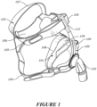
- a replacement seal module 101 can be inserted into the space in front of the face and connected to the rear side of the frame.
- the replacement seal module 101 may be the same type of seal module or a different type.
- the replacement module may be a full face seal module where the original seal module is a nasal seal module.
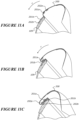
- Mask frame 100 is then released to close gap G so that the replacement seal is brought into engagement with the user's face.
- Magnetic connections 121a/121b and 122a/122b respectively join frame 100 to the 'replacement' seal module 101, aided by locating features 121c/121d to correctly orient the components and the magnets themselves which will tend to pull the assembly into place by magnetic forces.
- wedge shaped locator 121c approaches locator recess 121d to guide mask frame 100 into position against seal module 101 before or at the same time as the corresponding magnets begin to engage by magnetic attraction.
- magnets may be provided in the seal and/or frame to provide three or more, on only one, magnetic adjustment hold position.
- Figure 12 is a schematic side view of an embodiment of a respiratory interface comprising a nasal seal part and an oral seal part which are detachably magnetically coupled.
- the interface comprises an oral seal first part 300 to deliver gases through the mouth, supplied in the embodiment shown to the interface via conduit 301, and a nasal seal second part 302 to deliver gases to the nose also.
- the nasal seal part 301 may be an indirect or direct nasal seal as described.
- a magnetic coupling system magnetically couples the oral seal part 300 and nasal seal part 302 together to form, when coupled, a combined oro-nasal seal.
- the oral seal part 300 comprises magnets 303 around an upper peripheral part and the nasal seal part comprises magnets 304 around a lower peripheral part, both on left and right sides and across the front of the seal, or alternatively a single strip magnet in each seal part instead of discrete magnets as shown, or embedded particulate magnetic material, embedded in the seal during moulding for example, which magnetically couple the seal parts together or embedded particulate magnetic material, embedded in a soft synthetic insert 350 during plastic moulding for example.
- the seal parts may be attached to one another or coupled, and detached from one another, so that the interface may be used with both seal pats together or with the oral seal part only.
- the conduit may connect to a nasal seal part so that an oral seal part may be magnetically coupled to or detached from the nasal seal part enabling the nasal seal part to be used alone.
- the two seal parts 300 and 302 magnetically couple together but in an alternative embodiment one or both of the seal parts may also or alternatively magnetically couple to a common mask frame, again so that one or other of the seal parts may be detached to enable the interface to be used as an oral-only, or nasal-only, interface if the other seal part is detached.
- At least one magnet associated with one of the first or second seal parts or the mask frame and at least one magnet associated with another of the first or second seal parts or the mask frame are provided to the seal parts or mask frame such that they attract when the seal parts are coupled each other or to the mask frame in a predetermined correct orientation and repel in any orientation other than said predetermined correct orientation.
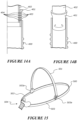
- Figure 13 is a perspective view from above of an embodiment of an oral insert configured to be retained in a user's mouth when a mask is worn, to assist in retaining the mask in position on the face of the user.
- Oral insert 350 is configured to be retained at least in part on the teeth of the user.
- the oral insert 350 has an approximate U-shape as shown, and comprises an upwardly facing open channel 351, so that it is configured to be retained on the left right and front upper teeth of the user when worn.
- the insert may be formed of a material which is soft but has some structural rigidity, such as a silicone material for example.
- the dimensions across the upwardly facing channel 351 are such that the insert will remain wedged on the teeth.
- the insert comprises magnets 352 spaced around its forward periphery as shown, or alternatively a single magnetic strip may extend around the front periphery of the insert.
- the magnets or magnetic strip may comprise a solid magnet or magnets or embedded particulate magnetic material, embedded in a soft synthetic insert 350 during plastic moulding for example.
- the magnetic coupling system comprises at least one magnet associated with one of the mask or oral insert and at least one ferrous part associated with the other of the mask or oral insert. In embodiments the magnetic coupling system comprises magnets associated with both of the mask or oral insert.
- Annular magnets 403 are embedded in the part 401, for example during plastic moulding of the part 401, and corresponding annular magnets 404 are embedded in the part 402 during moulding of this part for example.
- the magnets 403 and 404 are positioned, and part 401 has a slight internal taper and part 402 a slight external taper, so that when the parts 401 and 402 are brought together the magnets will align and magnetically couple part 401 on the end of conduit 400 to the part 402 on the bottom end of the elbow or mask lead in tube.
- the magnetic coupling may or may not form a frictionless or near frictionless swivel ie the part 401 can rotate about the longitudinal axis of the coupling without becoming detached from the part 402.
- the magnetic coupling system comprises at least one magnet associated with one of the conduit to the mask and the mask or a lead in tube to the mask and at least one ferrous part associated with another of the conduit to the mask and the mask or a lead in tube to the mask. In embodiments the magnetic coupling system comprises magnets associated with both of the conduit to the mask and the mask or a lead in tube to the mask.
- At least one magnet associated with one of the conduit to the mask and the mask or a lead in tube to the mask and at least one magnet associated with another of the conduit to the mask and the mask or a lead in tube to the mask are provided to the conduit and the mask or a lead in tube to the mask such that they attract when the conduit and the mask or a lead in tube to the mask are coupled each other or to the mask frame in a predetermined correct orientation and repel in any orientation other than said predetermined correct orientation.
- Figures 36 and 37 schematically show components of an embodiment of a respiratory interface having a magnetic coupling system 450 for connecting a conduit to a mask or to a lead in tube to the mask to deliver respiratory gases to the user.
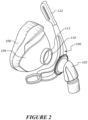
- the illustrated components of the respiratory interface are a seal module 101 and elbow 102.
- the seal module 101 and elbow 102 may have the features and operation of earlier described embodiments, except the differences described below.
- Figures 38a and 38b are schematic views of magnet parts of the seal module 101 and elbow 102 in incorrect and correct orientations relative to one another respectively.
- the outlet aperture 111 of the elbow and the inlet aperture 110 of the seal module are aligned.
- Figure 38a shows the misalignment of the apertures' 110, 111 central axis when the seal module and the elbow are incorrectly oriented.
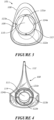
- the magnetic coupling system 450 comprises two annular magnets 451, 453 provided in the seal module 101 with a space between them. One magnet is a coupling magnet 453 and one magnet is a repulsing magnet 451. Both magnets 451, 453 surround and are spaced from the inlet aperture 110 of the seal module 101.
- the magnetic coupling system 450 also comprises an annular magnet 455 in the elbow 102 in a location such that it will align with the coupling magnet 453 on the seal module 101 when the elbow is correctly orientated with respect to the seal module.
- the elbow 102 has a flexible flange 457 and the annular magnet 455 is provided at or near a periphery of the flexible flange 457.
- the flange 457 extends outwardly from the elbow 102 and extends around the perimeter of the elbow. Although it is to be appreciated that in other embodiments the flange only extends around a portion of the elbow or comprises a plurality of flange segments that are distributed about the perimeter of the elbow.
- the flange 457 is located close to the outlet aperture 111 of the elbow.
- the flange 457 is configured to be positioned over a portion of the seal module's external surface surrounding the inlet aperture 110. The flexibility of the flange enables the flange to conform to the shape of the seal module's external surface and form a seal.
- the magnets 451, 453, 455 are shown as unitary annular magnets, in other embodiments one or more of the magnets comprises two or more magnets in an annular arrangement. Any or all of the annular magnets 451, 453, 455 can be made from a soft magnetic material, such that it is conformable to the geometry of the seal module 101. A soft magnet may provide an airtight connection between the seal module 101 and the elbow 102.
- the coupling magnet 453 in the seal module 101 has an opposite pole (for example north) to the magnet 455 of the elbow 102 (for example south).
- the repulsing magnet 451 will have the same pole as the magnet 455 of the elbow 102 (for example south).
- the seal module 101 and elbow 102 will attract only in one (correct) orientation and/or position of the seal module 101 relative to the elbow, as illustrated by Figures 38a - incorrect orientation, and 38b - correct orientation.
- the magnets 451, 453, 455 will encourage the elbow 102 to move towards the correct orientation and/or position. This will occur if the elbow 102 is correctly aligned and is then moved or knocked. That is, the elbow 102 is self-centring or self-locating. If a user places the elbow 102 near the seal module 101, the magnets 451, 453, 455 will encourage the elbow 102 towards the correct orientation.
- interfaces of the invention may rely solely on magnetic attraction of the seal module 101 to the elbow 102.
- a magnetic coupling system supplements, and is provided in addition to, other coupling systems as described above.
- the interface relies predominantly on mechanical coupling to hold the seal module 101 relative to the elbow 102, and a magnetic coupling system as described is provided primarily to self-centre the seal module 101.
- Figure 15 schematically shows an embodiment of headgear for a respiratory interface, comprising headgear parts and a magnetic coupling system arranged to magnetically couple headgear parts to one another.
- the headgear comprises a rear strap 500 and top or crown strap 501, which couple magnetically to the ends of left and right side straps or side arms 503 from mask 504, which extend in use across the left and right sides of the face of the wearer.
- landing parts 503a are provided at the ends of side straps or arms 503.
- the left and right ends of rear strap 500 comprise a magnet or magnets and the left and right ends of top strap 501 each comprise a magnet or magnets, as do the landing parts 503a of left and right side straps or arms 503, so that the ends of the rear strap 500 and top strap 501 can be coupled to the ends 503a of the side straps or arms 503, to assemble the headgear for use as shown.
- first and second, and optionally third or third and fourth headgear parts comprise at least one magnet at or towards one end thereof and at least one ferrous part at or towards another end thereof.
- Headgear in any form such as bifurcated or four point headgear having both top and bottom side straps to the interface on left and right sides, may be formed in whole or part as described so that for example headgear may have a top strap which is attached to the rest of the headgear magnetically and can be removed if desired by the user.
- Headgear buckle also headgear to mask buckle
- Figures 16A and 16B show embodiments of headgear for a respiratory interface comprising a magnetic coupling system to magnetically couple headgear straps or parts together.
- Straps 540 and 542 adjustably connect together.
- Strap 540 carries protrusion 541 having a magnet or magnets associated therewith such as embedded in the strap at and within the protrusion during moulding of a plastic strap for example, or embedded in a separate plastic part in turn bonded to a strap of soft material strap such as Breath-O-Prene ® or similar material strap for example.
- Strap 542 carries a series of adjacent apertures 543 each having a small annular magnet embedded in the strap around the aperture. The magnet in protrusion 541 and associated with apertures 543 are oriented such that when the protrusion 541 is entered into one of the apertures 543 it will magnetically attract to and couple to the strap.
- Figure 16B shows a similar embodiment in which protrusion 553 is provided on the underside of the end of strap 552, and recesses 551 which are optionally semi-connected to form a channel with corrugated sides as shown, are provided in the end of strap 550.
- the apertures 543 may penetrate completely through the strap end
- the apertures 551 are blind and magnet or magnetic particulate material alternatively are embedded during plastic moulding of the strap for example in the base of the apertures 551.
- This embodiment also comprises a loop 554 through which the strap end 552 passes before connecting to strap 550.
- the magnetic protrusion 541 or 553 may be provided at or towards the end of a side strap which couples to a mask or forehead rest part of a mask, and apertures 543 or 551 provided on the left and right sides of the mask body or forehead rest, to couple the side straps to the mask body or forehead rest in the same way.
- first headgear part comprises at least one magnet or at least one ferrous part associated with said protrusion and the second headgear part or mask comprises at least one magnet or at least one ferrous part associated with said one or more recesses.
- headgear comprises the first headgear part comprises at least one magnet associated with said protrusion and the second headgear part or mask comprises at least one magnet associated with said one or more recesses.
- portions of the headgear assembly can be substantially non-stretchable.
- the back strap, top strap and upright straps can be non-stretchable such that the portion that encircles the occipital region of the users head is made from non-stretch material.
- non-stretchable portions can comprise of a substantially non-stretch insert.
- the non-stretch insert can be attached to the headgear assembly, for example, by over-lock stitching, by ultrasonic welding, by use of glue or other adhesives, or by any other method.
- one or more of the side straps can also be formed of a substantially inelastic or non-stretchable material.
- the semi-rigid headgear can be formed as a composite structure comprising a semi-rigid strap that is joined to a soft edging.
- the soft edging can be bonded to the semi-rigid strap by plastic overmolding or by use of an adhesive.
- the soft edging can be butt-joined to the semi-rigid strap, without the soft edging overlapping the semi-rigid strap, to maintain the continuous profile of the semi-rigid headgear.
- the semi-rigid strap can define and maintain the semi-rigid headgear shape as tension is applied from the straps to pull the mask assembly towards the user's head.
- the semi-rigid strap can be sufficiently rigid along its planar axis to prevent its upper and lower side straps from overly deforming under tension.
- the semi-rigid strap can be made from a variety of rigid or semi-rigid materials, including plastic or metal. In some configurations, the semi-rigid strap is made from PVC.
- the shape holding, or self-supporting nature can result in an overall assembly that is intuitive to fit.
- the connection and/or headgear members are self-supporting such that they maintain a three-dimensional form as discussed earlier, the headgear can be fitted in the correct orientation with very little if any instruction.
- the tendency of the straps to not tangle also reduces the time taken to fit the overall assembly.
- the term "semi-rigid" is used to denote that the headgear assembly is sufficiently stiff such that the headgear assembly can assume a three-dimensional shape with dimensions approximating the head of the user for which the headgear is designed to fit while also being sufficiently flexible to generally conform to the anatomy of the user.
- some of the other components (e.g., side straps) of the headgear assembly may also be partially or wholly "semi-rigid" such that the components are capable of holding a three-dimensional form that is substantially self-supporting.
- a "semi-rigid" headgear assembly is not intended to mean that each and every component of the headgear assembly is necessarily semi-rigid.
- the substantially three-dimensional form that the self-supporting headgear assembly may assume may relate primarily to the rear and top portions of the headgear assembly.
- the semi-rigid headgear assembly may include semi-rigid regions that extend forward of the ears and above the ears when placed on the head of the patient.
- the upper and lower side straps can be formed of a semi-rigid material, as well.
- the semi-rigid materials can include molded plastic or sheet materials that include, but are not limited to, homogeneous plastic materials and bonded non-woven fiber materials.
- the semi-rigid properties of the materials can be achieved with high-density foam material.
- the dense foam material can provide some structural rigidity to the upper and lower side straps, or other portions of the headgear assembly.
- the semi-rigid material can include textiles that are semi-rigid, such as denim or hemp.
- the material can comprise a laminate structure of both conformable and semi-rigid portions, for example but without limitation.
- the semi-rigid straps may be of a self-supporting, resilient, substantially inelastic material, such as Santoprene, polyolefin, polypropylene, polyethylene, foamed polyolefin, nylon or non-woven polymer material for example but without limitation.
- the semi-rigid strap is formed from the polyethylene or polypropylene families.
- the semi-rigid strap can be formed of a material such that the semi-rigid headgear is substantially shape-sustaining under its own weight regardless of its orientation. A soft edging can cover or attach to at least a portion of the periphery of the semi-rigid strap.
- the soft edging does not cover the front or rear faces of the semi-rigid strap and is instead attached adjacent to the edge of the semi-rigid strap.
- the thicknesses of the soft edging and semi-rigid strap can be the same at the location where they are joined together.
- "soft” is used to describe a hand of the material, which means the quality of the material assessed by the reaction obtained from the sense touch.
- "conformable” is used to describe the ability of the material to conform to the anatomical features of the patient (e.g., around a facial feature).
- material thickness may be symmetrically or asymmetrically applied to the semi-rigid strap.
- material thickness may be symmetrically or asymmetrically applied to the semi-rigid strap.
- the thickness of either end the soft edging is symmetrically applied to the semi-rigid strap.
- the semi-rigid strap is selectively thickened to provide extra rigidity and support.
- venting through-holes are provided throughout the semi-rigid headgear (such as on the semi-rigid strap or on soft edging) to provide ventilation and sweat management.
- a magnetic repulsing system is shown that is adapted to be incorporated into a conduit for delivering respiratory gases to a user.
- the conduit is connectable to a mask or to a lead in tube to the mask and comprises an inlet, an outlet, and an enclosing wall defining at least one gases passageway between said inlet and said outlet.
- the magnetic repulsing system is incorporated into the enclosing wall to magnetically repulse a portion of the wall from a diametrically opposite portion of the wall.
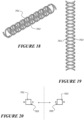
- the magnetic repulsing system comprises one or more magnets that are spiral or helically shaped magnets.
- the embodiment of figures 18 to 22 has two spiral or helically shaped magnets of which one spirals in a clockwise direction 701 and the other spirals in a counterclockwise direction 703.
- the magnetic repulsing system comprises a single spiral or helically shaped magnet.
- the inner surfaces 705 of the magnets that face each other are the same pole and repel each other. As a consequence, the repulsion prevents or at least substantially inhibits the conduit from being crushed or compressed.
- a magnetic system according to another embodiment that is adapted to be incorporated into a conduit for delivering respiratory gases to a user, is shown.
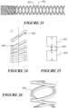
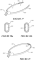
- the magnetic system is arranged to magnetically collect, i.e. automatically retract and/or retain, a portion of a length of an enclosing wall of the conduit.
- the adjacent surfaces 805 of the magnets are the opposite poles and attract each other.
- the magnet collects a length of the conduit into a shorter length.
- the conduit may stretch, fold, or gather between the longer and shorter lengths. As the conduit, or a portion of the conduit, is stretched or pulled, the adjacent magnet portions will initially work against the pulling force and maintain the conduit in the shorter length.
- Figure 24 shows a portion of conduit in which the lower portion is collected by the magnetic coupling system and the upper portion is configured such that the adjacent magnetic portions are spaced at a distance that is greater than their fields reach so the conduit is not collected.
- the magnets may comprise a segment of solid (non-particulate) magnetic material or may comprise particulate magnetic material.
- the particulate magnetic is material embedded in a part of the conduit.
- the particulate magnetic material may be integrally formed with the enclosed wall, such as during an extrusion process.
- the magnets may extend along part of, substantially most of, or the entire length of the conduit.
- the magnets may extend around only part of the circumference of the conduit.
- the enclosing wall is preferably a soft and flexible material.
- the soft and flexible material is comfortable against the wearer's face, such as a silicone material.
- the magnets are preferably formed from soft magnetic material and thus provide the conduit with a soft and flexible feel for the patient.
- the material may also provide a grip to anchor or secure the hose to adjacent objects, such as a bed cover ( Figure 22 ).
Landscapes
- Health & Medical Sciences (AREA)
- Pulmonology (AREA)
- General Health & Medical Sciences (AREA)
- Public Health (AREA)
- Anesthesiology (AREA)
- Biomedical Technology (AREA)
- Heart & Thoracic Surgery (AREA)
- Hematology (AREA)
- Life Sciences & Earth Sciences (AREA)
- Animal Behavior & Ethology (AREA)
- Emergency Medicine (AREA)
- Engineering & Computer Science (AREA)
- Veterinary Medicine (AREA)
- Otolaryngology (AREA)
- Respiratory Apparatuses And Protective Means (AREA)
- Acyclic And Carbocyclic Compounds In Medicinal Compositions (AREA)
- Pharmaceuticals Containing Other Organic And Inorganic Compounds (AREA)
- Steroid Compounds (AREA)
- Water Treatment By Electricity Or Magnetism (AREA)
- Financial Or Insurance-Related Operations Such As Payment And Settlement (AREA)
Applications Claiming Priority (5)
| Application Number | Priority Date | Filing Date | Title |
|---|---|---|---|
| US201662358731P | 2016-07-06 | 2016-07-06 | |
| US201662412399P | 2016-10-25 | 2016-10-25 | |
| US201662438207P | 2016-12-22 | 2016-12-22 | |
| PCT/IB2017/054060 WO2018007966A1 (en) | 2016-07-06 | 2017-07-06 | Respiratory interface |
| EP17823742.6A EP3481478B1 (de) | 2016-07-06 | 2017-07-06 | Respiratorische schnittstelle |
Related Parent Applications (2)
| Application Number | Title | Priority Date | Filing Date |
|---|---|---|---|
| EP17823742.6A Division EP3481478B1 (de) | 2016-07-06 | 2017-07-06 | Respiratorische schnittstelle |
| EP17823742.6A Division-Into EP3481478B1 (de) | 2016-07-06 | 2017-07-06 | Respiratorische schnittstelle |
Publications (2)
| Publication Number | Publication Date |
|---|---|
| EP4574192A2 true EP4574192A2 (de) | 2025-06-25 |
| EP4574192A3 EP4574192A3 (de) | 2025-09-10 |
Family
ID=60901341
Family Applications (2)
| Application Number | Title | Priority Date | Filing Date |
|---|---|---|---|
| EP17823742.6A Active EP3481478B1 (de) | 2016-07-06 | 2017-07-06 | Respiratorische schnittstelle |
| EP25162160.3A Pending EP4574192A3 (de) | 2016-07-06 | 2017-07-06 | Respiratorische schnittstelle |
Family Applications Before (1)
| Application Number | Title | Priority Date | Filing Date |
|---|---|---|---|
| EP17823742.6A Active EP3481478B1 (de) | 2016-07-06 | 2017-07-06 | Respiratorische schnittstelle |
Country Status (5)
| Country | Link |
|---|---|
| US (1) | US20190175863A1 (de) |
| EP (2) | EP3481478B1 (de) |
| AU (3) | AU2017292403B2 (de) |
| SG (2) | SG10202100075VA (de) |
| WO (1) | WO2018007966A1 (de) |
Families Citing this family (43)
| Publication number | Priority date | Publication date | Assignee | Title |
|---|---|---|---|---|
| US8783257B2 (en) | 2004-02-23 | 2014-07-22 | Fisher & Paykel Healthcare Limited | Breathing assistance apparatus |
| WO2005094928A1 (en) | 2004-04-02 | 2005-10-13 | Fisher & Paykel Healthcare Limited | Breathing assistance apparatus |
| EP3738636B1 (de) | 2006-07-14 | 2023-06-07 | Fisher & Paykel Healthcare Limited | Atemhilfsgerät |
| US10792451B2 (en) | 2008-05-12 | 2020-10-06 | Fisher & Paykel Healthcare Limited | Patient interface and aspects thereof |
| US11660413B2 (en) | 2008-07-18 | 2023-05-30 | Fisher & Paykel Healthcare Limited | Breathing assistance apparatus |
| EP2349428B1 (de) | 2008-10-10 | 2017-09-20 | Fisher & Paykel Healthcare Limited | Nasale kissen für eine patientenschnittstelle |
| EP4640259A3 (de) | 2010-10-08 | 2025-11-12 | Fisher & Paykel Healthcare Limited | Maskendichtungsanordnung |
| CA2833106C (en) | 2011-04-15 | 2019-08-27 | Fisher & Paykel Healthcare Limited | Interface comprising a rolling nasal bridge portion |
| US10603456B2 (en) | 2011-04-15 | 2020-03-31 | Fisher & Paykel Healthcare Limited | Interface comprising a nasal sealing portion |
| EP3566736B1 (de) | 2011-07-01 | 2020-12-09 | Fisher & Paykel Healthcare Limited | Schnittstellenanordnung für eine nasalmaske |
| USD693459S1 (en) | 2011-09-16 | 2013-11-12 | Fisher & Paykel Healthcare Limited | Patient interface assembly |
| SG11201604124UA (en) | 2012-08-08 | 2016-07-28 | Fisher & Paykel Healthcare Ltd | Headgear for patient interface |
| US9950130B2 (en) | 2012-09-04 | 2018-04-24 | Fisher & Paykel Healthcare Limited | Valsalva mask |
| SG10202102503YA (en) | 2014-08-25 | 2021-04-29 | Fisher & Paykel Healthcare Ltd | Respiratory mask and related portions, components or sub-assemblies |
| USD784516S1 (en) | 2015-09-25 | 2017-04-18 | Fisher & Paykel Healthcare Limited | Face mask frame |
| USD784515S1 (en) | 2015-09-25 | 2017-04-18 | Fisher & Paykel Healthcare Limited | Headgear |
| USD800895S1 (en) | 2015-09-25 | 2017-10-24 | Fisher & Paykel Healthcare Limited | Face mask cushion |
| CN109843104B (zh) | 2016-07-18 | 2022-11-25 | 造雨人解决方案有限公司 | 补水系统及其部件 |
| US10492552B2 (en) | 2016-11-17 | 2019-12-03 | Rainmaker Solutions, Inc. | Hydration and audio system |
| US20180193676A1 (en) * | 2016-11-17 | 2018-07-12 | Rainmaker Solutions, Inc. | Hydration and air cooling system |
| US10765827B2 (en) * | 2017-03-28 | 2020-09-08 | Koninklijke Philips N.V. | Magnetically controlled forehead support |
| EP3755409A4 (de) * | 2018-02-23 | 2021-11-24 | Bespoke Medical Innovations Pty Ltd. | Oro-nasale patientenschnittstelle zur behandlung von atemstörungen im schlaf |
| EP3773846B1 (de) | 2018-03-29 | 2023-11-29 | ResMed Pty Ltd | Leitung mit magnetischem verbinder |
| EP3643348B1 (de) * | 2018-10-26 | 2023-03-08 | Air Liquide Medical Systems | Nasenkissenmaske mit kombiniertem poka-yoke-kopplungssystem und magnetischem verbindungssystem |
| US11554236B2 (en) * | 2018-12-24 | 2023-01-17 | Koninklijke Philips N.V. | Patient interface device having magnetic coupling features |
| US11058840B2 (en) * | 2019-01-17 | 2021-07-13 | Makrite Industries Inc. | Retractable respiratory mask |
| US10959493B2 (en) * | 2019-07-10 | 2021-03-30 | Gabriel Raynolds | Attachment mechanism for face mask |
| EP3996786A4 (de) | 2019-07-11 | 2023-07-26 | Snap Cpap, LLC | Beatmungsanordnung und verfahren zur verwendung davon |
| WO2021067155A1 (en) | 2019-09-30 | 2021-04-08 | Snap Cpap, Llc | Respiratory assembly with conduit adapter and methods of use |
| CN110947063B (zh) * | 2019-11-27 | 2020-11-17 | 吉林大学 | 一种心血管内科护理用防咬伤型通气导管 |
| JP7651196B2 (ja) | 2020-03-21 | 2025-03-26 | スナップ シーパップ,エルエルシー | 持続的気道陽圧(cpap)装置と共に使用するための呼吸マスクアセンブリ |
| US20220031990A1 (en) * | 2020-07-29 | 2022-02-03 | ResMed Asia Pte Ltd | Patient interface system and components therefor |
| KR102946738B1 (ko) * | 2020-09-02 | 2026-04-02 | 엘지전자 주식회사 | 마스크 장치 |
| CN116234599A (zh) * | 2020-09-30 | 2023-06-06 | 皇家飞利浦有限公司 | 用于患者接口的包绕头套 |
| US12465711B2 (en) | 2020-12-21 | 2025-11-11 | Koninklijke Philips N.V. | Mask with quick release frame and headgear |
| KR102498505B1 (ko) * | 2021-07-19 | 2023-02-10 | 엘지전자 주식회사 | 마스크 장치 |
| KR102426354B1 (ko) * | 2021-07-19 | 2022-07-29 | 엘지전자 주식회사 | 마스크 장치 |
| KR102475624B1 (ko) * | 2021-07-19 | 2022-12-08 | 엘지전자 주식회사 | 마스크 장치 |
| US11471634B1 (en) | 2021-12-14 | 2022-10-18 | ResMed Pty Ltd | Oro-pillow cushion assembly |
| USD1116088S1 (en) | 2022-01-31 | 2026-03-03 | ResMed Asia Pte. Ltd. | Patient interface |
| CN114503932B (zh) * | 2022-02-21 | 2023-04-07 | 山东卡尔电气股份有限公司 | 一种宠物定位器 |
| US20230285707A1 (en) * | 2022-03-09 | 2023-09-14 | ResMed Asia Pte. Ltd. | Air circuit for a respiratory therapy system |
| USD1115021S1 (en) * | 2024-05-22 | 2026-02-24 | Fisher & Paykel Healthcare Limited | Mask assembly |
Citations (2)
| Publication number | Priority date | Publication date | Assignee | Title |
|---|---|---|---|---|
| WO2012140514A1 (en) | 2011-04-15 | 2012-10-18 | Fisher & Paykel Healthcare Limited | Interface comprising a rolling nasal bridge portion |
| WO2014175752A2 (en) | 2013-04-24 | 2014-10-30 | Fisher & Paykel Healthcare Limited | Automatically adjusting headgear for patient interface |
Family Cites Families (20)
| Publication number | Priority date | Publication date | Assignee | Title |
|---|---|---|---|---|
| US3181895A (en) * | 1960-09-27 | 1965-05-04 | Crawford Fitting Co | Quick-connect magnetic couplings |
| US3582017A (en) * | 1968-09-13 | 1971-06-01 | Ltv Aerospace Corp | Magnetic separation device |
| US5096230A (en) * | 1991-03-20 | 1992-03-17 | General Resource Corporation | Quick release adapter for connecting an exhaust removal hose to a vehicle tail pipe using magnets |
| US6668828B1 (en) * | 2000-10-16 | 2003-12-30 | Pulmonox Technologies Corporations | System and elements for managing therapeutic gas administration to a spontaneously breathing non-ventilated patient |
| US6805117B1 (en) * | 2001-11-07 | 2004-10-19 | Ric Investments, Llc | Universal fitting headgear |
| US8042542B2 (en) * | 2002-04-23 | 2011-10-25 | Resmed Limited | Respiratory mask assembly with magnetic coupling to headgear assembly |
| DE102004006259B3 (de) * | 2004-02-09 | 2005-10-13 | S-Y Systems Technologies Europe Gmbh | Kontaktanordnung mit einer Batterie und einer elektrischen Leitung |
| US7793987B1 (en) * | 2006-03-24 | 2010-09-14 | Ric Investments, Llc | Magnetic coupling assembly and method of using same |
| WO2009108994A1 (en) * | 2008-03-04 | 2009-09-11 | Resmed Ltd | A foam respiratory mask |
| US20110084474A1 (en) * | 2008-06-25 | 2011-04-14 | Paden David B | High retention magnetic coupling device for conduit attachment |
| CN107050610B (zh) * | 2009-11-12 | 2019-10-15 | 费雪派克医疗保健有限公司 | 病人接口及其多个方面 |
| US9140393B2 (en) * | 2012-04-20 | 2015-09-22 | Husky Corporation | Fuel line breakaway connector secured by plurality of individually spaced magnets |
| US8608502B2 (en) * | 2012-05-08 | 2013-12-17 | Otter Products, Llc | Connection mechanism |
| SG11201604124UA (en) * | 2012-08-08 | 2016-07-28 | Fisher & Paykel Healthcare Ltd | Headgear for patient interface |
| RU2650074C2 (ru) * | 2012-09-21 | 2018-04-06 | Конинклейке Филипс Н.В. | Респираторная маска, имеющая накладку, удерживаемую путем магнитного воздействия |
| EP3348299B1 (de) * | 2013-01-18 | 2025-04-02 | ResMed Pty Ltd | Kopfhaubesystem und patienteninterface |
| CN105555345B (zh) * | 2013-08-05 | 2018-03-30 | 费雪派克医疗保健有限公司 | 用于在提供正压呼吸治疗中使用的接口及其与面罩组件的组合 |
| US9190198B2 (en) * | 2013-08-22 | 2015-11-17 | Apple Inc. | Magnetic fasteners |
| US10232137B2 (en) * | 2014-05-22 | 2019-03-19 | Resmed Limited | Patient interface |
| JP6177724B2 (ja) * | 2014-05-27 | 2017-08-09 | ファナック株式会社 | 工具把持機構 |
-
2017
- 2017-07-06 US US16/310,978 patent/US20190175863A1/en active Pending
- 2017-07-06 AU AU2017292403A patent/AU2017292403B2/en active Active
- 2017-07-06 EP EP17823742.6A patent/EP3481478B1/de active Active
- 2017-07-06 SG SG10202100075VA patent/SG10202100075VA/en unknown
- 2017-07-06 EP EP25162160.3A patent/EP4574192A3/de active Pending
- 2017-07-06 SG SG11201811318XA patent/SG11201811318XA/en unknown
- 2017-07-06 WO PCT/IB2017/054060 patent/WO2018007966A1/en not_active Ceased
-
2022
- 2022-09-16 AU AU2022231772A patent/AU2022231772B2/en active Active
-
2025
- 2025-04-28 AU AU2025202934A patent/AU2025202934A1/en active Pending
Patent Citations (2)
| Publication number | Priority date | Publication date | Assignee | Title |
|---|---|---|---|---|
| WO2012140514A1 (en) | 2011-04-15 | 2012-10-18 | Fisher & Paykel Healthcare Limited | Interface comprising a rolling nasal bridge portion |
| WO2014175752A2 (en) | 2013-04-24 | 2014-10-30 | Fisher & Paykel Healthcare Limited | Automatically adjusting headgear for patient interface |
Also Published As
| Publication number | Publication date |
|---|---|
| AU2022231772B2 (en) | 2025-02-06 |
| AU2022231772A1 (en) | 2022-10-06 |
| EP4574192A3 (de) | 2025-09-10 |
| EP3481478B1 (de) | 2025-04-09 |
| AU2025202934A1 (en) | 2025-05-15 |
| SG11201811318XA (en) | 2019-01-30 |
| SG10202100075VA (en) | 2021-02-25 |
| WO2018007966A1 (en) | 2018-01-11 |
| US20190175863A1 (en) | 2019-06-13 |
| AU2017292403A1 (en) | 2019-01-17 |
| EP3481478A1 (de) | 2019-05-15 |
| AU2017292403B2 (en) | 2022-10-13 |
| EP3481478A4 (de) | 2020-03-04 |
Similar Documents
| Publication | Publication Date | Title |
|---|---|---|
| AU2022231772B2 (en) | Respiratory interface | |
| JP7274548B2 (ja) | ロールする鼻梁部を有するインタフェース | |
| US11452834B2 (en) | Patient interface | |
| JP7350905B2 (ja) | 鼻を密閉する部分を含むインタフェース | |
| JP7038689B2 (ja) | マスクシステム | |
| US8561613B2 (en) | Respiratory mask assembly for stabilizing patient interface | |
| JP6046626B2 (ja) | マスクシステム | |
| JP2023080109A (ja) | 患者用インターフェースおよびその態様 | |
| JP2018202210A (ja) | 患者インタフェースおよび該患者インタフェースを形成する方法 | |
| KR20150038230A (ko) | 환자 인터페이스 및 그 제조 방법 | |
| CN101455871A (zh) | 患者接口 |
Legal Events
| Date | Code | Title | Description |
|---|---|---|---|
| PUAI | Public reference made under article 153(3) epc to a published international application that has entered the european phase |
Free format text: ORIGINAL CODE: 0009012 |
|
| STAA | Information on the status of an ep patent application or granted ep patent |
Free format text: STATUS: THE APPLICATION HAS BEEN PUBLISHED |
|
| AC | Divisional application: reference to earlier application |
Ref document number: 3481478 Country of ref document: EP Kind code of ref document: P |
|
| AK | Designated contracting states |
Kind code of ref document: A2 Designated state(s): AL AT BE BG CH CY CZ DE DK EE ES FI FR GB GR HR HU IE IS IT LI LT LU LV MC MK MT NL NO PL PT RO RS SE SI SK SM TR |
|
| PUAL | Search report despatched |
Free format text: ORIGINAL CODE: 0009013 |
|
| AK | Designated contracting states |
Kind code of ref document: A3 Designated state(s): AL AT BE BG CH CY CZ DE DK EE ES FI FR GB GR HR HU IE IS IT LI LT LU LV MC MK MT NL NO PL PT RO RS SE SI SK SM TR |
|
| RIC1 | Information provided on ipc code assigned before grant |
Ipc: A61M 16/06 20060101AFI20250801BHEP |
|
| STAA | Information on the status of an ep patent application or granted ep patent |
Free format text: STATUS: REQUEST FOR EXAMINATION WAS MADE |
|
| GRAP | Despatch of communication of intention to grant a patent |
Free format text: ORIGINAL CODE: EPIDOSNIGR1 |
|
| STAA | Information on the status of an ep patent application or granted ep patent |
Free format text: STATUS: GRANT OF PATENT IS INTENDED |
|
| 17P | Request for examination filed |
Effective date: 20260114 |
|
| INTG | Intention to grant announced |
Effective date: 20260129 |