EP4572345A2 - Verfahren und system zur drahtlosen kommunikation in einem fördersystem - Google Patents
Verfahren und system zur drahtlosen kommunikation in einem fördersystem Download PDFInfo
- Publication number
- EP4572345A2 EP4572345A2 EP24214609.0A EP24214609A EP4572345A2 EP 4572345 A2 EP4572345 A2 EP 4572345A2 EP 24214609 A EP24214609 A EP 24214609A EP 4572345 A2 EP4572345 A2 EP 4572345A2
- Authority
- EP
- European Patent Office
- Prior art keywords
- wireless
- track
- pallet
- wireless hub
- hub
- Prior art date
- Legal status (The legal status is an assumption and is not a legal conclusion. Google has not performed a legal analysis and makes no representation as to the accuracy of the status listed.)
- Pending
Links
Images


Classifications
-
- H—ELECTRICITY
- H04—ELECTRIC COMMUNICATION TECHNIQUE
- H04W—WIRELESS COMMUNICATION NETWORKS
- H04W64/00—Locating users or terminals or network equipment for network management purposes, e.g. mobility management
- H04W64/003—Locating users or terminals or network equipment for network management purposes, e.g. mobility management locating network equipment
-
- B—PERFORMING OPERATIONS; TRANSPORTING
- B65—CONVEYING; PACKING; STORING; HANDLING THIN OR FILAMENTARY MATERIAL
- B65G—TRANSPORT OR STORAGE DEVICES, e.g. CONVEYORS FOR LOADING OR TIPPING, SHOP CONVEYOR SYSTEMS OR PNEUMATIC TUBE CONVEYORS
- B65G43/00—Control devices, e.g. for safety, warning or fault-correcting
-
- H—ELECTRICITY
- H04—ELECTRIC COMMUNICATION TECHNIQUE
- H04W—WIRELESS COMMUNICATION NETWORKS
- H04W4/00—Services specially adapted for wireless communication networks; Facilities therefor
- H04W4/02—Services making use of location information
- H04W4/021—Services related to particular areas, e.g. point of interest [POI] services, venue services or geofences
-
- H—ELECTRICITY
- H04—ELECTRIC COMMUNICATION TECHNIQUE
- H04W—WIRELESS COMMUNICATION NETWORKS
- H04W4/00—Services specially adapted for wireless communication networks; Facilities therefor
- H04W4/02—Services making use of location information
- H04W4/025—Services making use of location information using location based information parameters
- H04W4/027—Services making use of location information using location based information parameters using movement velocity, acceleration information
-
- H—ELECTRICITY
- H04—ELECTRIC COMMUNICATION TECHNIQUE
- H04W—WIRELESS COMMUNICATION NETWORKS
- H04W4/00—Services specially adapted for wireless communication networks; Facilities therefor
- H04W4/02—Services making use of location information
- H04W4/029—Location-based management or tracking services
Definitions
- This application generally relates to conveyor systems and methods, and more specifically to wireless communications in a conveyor system, including wireless communication with an accessory provided to a moving element in the conveyor system.
- One developing area for conveyor systems including belt or scroll driven conveyors as well as, more recently, linear motor driven conveyors, is to provide power for use on the moving element/pallet when the moving element/pallet is moving.
- While power sources can be provided to a moving element/pallet by using batteries, the batteries can be bulky and require regular recharging. Power can also be provided by cabling, but this generally requires guidance systems for the cabling during movement and can limit the range of motion.
- a method for wireless communication with accessories on moving elements in a conveyor system including a conveyor controller for independently controlling the moving elements, the method including: configuring two or more track wireless hubs to cover respective wireless zones, each providing wireless coverage for at least a portion of the conveyor system; configuring two or more moving elements on the conveyor system with pallet wireless hubs configured to communicate with the two or more track wireless hubs; communicating between the conveyor controller and at least one of the two or more track wireless hubs when one of the moving elements having a predetermined identification is entering the wireless zone for the at least one of the two or more track wireless hubs; performing a simplified connection between the track wireless hub and the pallet wireless hub of the entering moving element based on the predetermined identification; and controlling an accessory on the entering moving element using communications from the conveyor controller via the track wireless hub and the pallet wireless hub.
- the method may further include: communicating between the conveyor controller and the track wireless hub when one of the moving elements having a predetermined identification is leaving the wireless zone for the track wireless hub; and discontinuing communication of the track wireless hub with the pallet wireless hub for the leaving moving element.
- the method may include, prior to discontinuing communication, sending a communication locking the accessory prior to the moving element leaving the wireless zone.
- the locking the accessory may include causing the accessory to: stop; continue operating in the same way; perform one or more operations for a predetermined period of time; perform one or more operations for a predetermined number of operations, or the like.
- the performing a simplified connection may include a message from the track wireless hub to the pallet wireless hub containing the predetermined identification and a basic acknowledgement of communications from the pallet wireless hub to the track wireless hub.
- the basic acknowledgement of communications may include a single bit that is toggled on each message thereafter from the pallet wireless hub to indicate that the pallet wireless hub is operational.
- the communications between the track wireless hub and pallet wireless hub may be implemented using a simplified communications protocol.
- the simplified communications protocol may use messages of less than two bytes.
- a system for wireless communication with accessories on moving elements in a conveyor system including a conveyor controller for independently controlling the moving elements, the system including: two or more track wireless hubs configured to cover respective wireless zones providing wireless coverage for at least a portion of the conveyor system; and at least two pallet wireless hubs provided to at least some moving elements on the conveyor system and configured to communicate with the two or more track wireless hubs, wherein: the conveyor controller is configured to communicate with at least one of the two or more track wireless hubs when one of the moving elements having a predetermined identification is entering a related wireless zone for the at least one of the two or more track wireless hubs; the track wireless hub and the pallet wireless hub of the entering moving element are configured to perform a simplified connection based on the predetermined identification; and the pallet wireless hub is configured to provide communications received from the track wireless hub to an accessory controller on the entering moving element for controlling an accessory on the entering moving element based on the communications.
- the conveyor controller may be configured to communicate with the track wireless hub when one of the moving elements is leaving the wireless zone for the track wireless hub and provide the predetermined identification for the leaving moving element; and cause the track wireless hub to discontinue communication with the pallet wireless hub based on the predetermined identification for the leaving moving element.
- the track wireless hub may, prior to discontinuing communication, send a communication locking the accessory prior to the moving element leaving the wireless zone.
- the locking the accessory may include causing the accessory to: stop; continue operating in the same way; perform one or more operations for a predetermined period of time; perform one or more operations for a predetermined number of operations, or the like.
- the performing a simplified connection may include a message from the track wireless hub to the pallet wireless hub containing the predetermined identification and a basic acknowledgement of communications from the pallet wireless hub to the track wireless hub.
- the basic acknowledgement of communications may include a single bit that is toggled on each message thereafter from the pallet wireless hub to indicate that the pallet wireless hub is operational.
- the communications between the track wireless hub and pallet wireless hub are implemented using a simplified communications protocol in which each message includes two bytes or less.
- a method for identifying moving elements in a conveyor system including a conveyor controller for independently controlling the moving elements, the method including: configuring at least one track wireless hub to provide wireless coverage for at least a portion of the conveyor system; configuring each of a plurality of moving elements on the conveyor system with a pallet wireless hub configured to communicate with the at least one track wireless hub; establishing wireless communications between the at least one track wireless hub and the pallet wireless hubs; independently vibrating each of the plurality of moving elements via the conveyor controller; identifying the vibration via an accelerometer provided to the moving element and communicating the accelerometer data to the conveyor controller via the pallet wireless hub and the track wireless hub; and identifying the plurality of moving elements based on the accelerometer data.
- FIG. 1 shows a schematic diagram of an example conveyor system 20.
- the conveyor system 20 includes a track 22 made up of one or more track sections 25, 26 defining a track.
- a plurality of straight track sections 25 are provided with two curved sections 26.
- a plurality of moving elements 35 are provided to the track and move around on the conveyor system 20.
- the moving elements 35 are intended to travel between workstations (not shown) and may support a pallet or product (not shown) that is to be operated on automatically by, for example, a robot, while moving or at a workstation or may travel to a workstation or other work area intended for manual operations.
- the terms "moving element” and “pallet” may sometimes be used interchangeably, depending on the context.
- the corner (or curved) track sections 26 are 180 degree turns but, in some configurations, the curved track sections 26 may have different angles such as 45, 90, 135 degree angles or the like.
- the conveyor system 20 may include a plurality of track sections 25, 26, which are mechanically self-contained and separable from one another so as to be modular in nature.
- each track section 25, 26 may house electronic circuitry and/or mechanical parts for powering and controlling the related track section 25, 26 and/or there may be a controller/control system 40 that controls the related track section or the track 22 overall (only one controller is shown but other controllers for track sections may be included as well, either together with a main/master controller or individually).
- a track controller may communicate or interface with track section controllers provided for each of the track sections 25, 26.
- the controller(s) may include a processor that executes a program stored on a machine readable medium.
- the machine-readable medium may be stored on memory that is a part of the controller or at a remote location or the like.
- the track 22 may produce a magnetic force for moving the moving element 35 along the track 22.
- the magnetic force can also capture, support or hold the moving element 35 on the track 22.
- the magnetic force is at least partly generated by the interaction of the magnetic flux created by magnetic elements (for example, embedded coils) of the track 22 and magnetic elements (for example, magnets) of the moving element 35.
- magnetic elements for example, embedded coils
- magnets for example, magnets
- the magnetic elements may have various arrangements on both the track 22 and the moving element 35. It will be understood that conveyor systems with different motor drives may be driven in other manners.
- Figure 2 illustrates a perspective view of an embodiment of a straight track section 25 and a moving element 35.
- the track section 25 includes a guide rail 45 located in an upper portion of track section 25 and a lower guide rail 50.
- the moving elements 35 include bearings (not visible in Fig. 2 ) that run along a corresponding guide rail 45, 50.
- the track section 25 may produce a magnetic force for moving the moving element 35 along the track 22.
- the magnetic force can also capture/hold the moving element 35 on the track 22.
- the magnetic force is created by the interaction of the magnetic flux created by coils (not shown) embedded in/under the track section 25 and magnetic elements (not shown) of the moving element 35.
- the magnetic force can be thought of as having a motive force component for directing movement of the moving element 35 along a direction of travel on the track 22, and a capturing force component to laterally hold the moving element 35 on the track 22 and in spaced relation to the track surface.
- the motive force and the capturing force can be provided by the same magnetic flux.
- each track section may be controlled by a control system or by a track control system 40 that controls a plurality of or all of the track sections 25.
- the control system 40 controls each track section (and thus the track) to drive the moving elements and also receives data related to a position of the moving elements on the track such that the controller effectively controls the moving elements.
- the control system 40 can control the servo motor and thus control the moving elements.
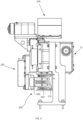
- Fig. 3 is a perspective view illustrating the track section 25 and moving element 35 of Fig. 2 as well as an accessory 100 mounted on the moving element 35.
- the accessory may be mounted on a pallet, tooling plate or the like carried by the moving element 35.
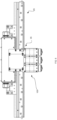
- Fig. 4 is a front view of the track section of Fig. 3 .
- Fig. 5 is a side cross-sectional view of Fig. 4 .
- Fig. 6 is a top view of Fig. 4 .
- Fig. 7 is a front perspective view of the moving element and the accessory.
- Fig. 8 is a back perspective view of the moving element and the accessory.
- each moving element 35 includes a body 200 which supports one or more permanent magnets 205 disposed to provide a magnetic flux orientated normal to the track section 25.
- Each moving element 35 includes upper bearings (not shown) and lower bearings 210 which ride along upper 45 and lower 50 guide rails of the track section 25.
- the track section 25 and the moving element 35 include a system 300 for transferring power wirelessly between the track section 25 and the moving element 35.
- Each moving element 35 includes a moving element power transfer unit 305 that is configured to interact with a track power transfer unit 310 provided on the track section 25.
- the moving element power transfer unit 305 includes one or more extensions 315 protruding toward the track section 25 and the track power transfer unit includes corresponding track extensions 320 on the track section 25 configured such that the moving element extensions 315 and corresponding track extensions 320 interlace.
- the moving element power transfer unit and the track power transfer unit are configured to inductively transfer power to the moving element, particularly while the moving element is moving.
- the provision of a plurality of track power transfer units along the track at regular intervals or potentially continuous and the inter-engaging structure of the extensions is intended to provide for a greater and more consistent transfer of power since there can be a smooth transfer of power with multiple induction elements.
- the extensions are sometimes referred to as power pick-up panels, energy pick-up elements, inductive pick-up elements or inductive panels.
- inductive transfer of power is used, and it will be understood that a single or larger number of induction panels may also be used.
- the induction panels include at least one induction pick-up coil (not shown) and one or more ferrite cores (not shown).
- the field of induction coils is well known and an appropriate coil and/or ferrite core arrangement can be chosen depending on the required power transfer.
- the moving element may also include an enclosure 225 for power management, accessory controller, battery or the like.
- the moving element may also include an enclosure 230 for a DC/DC converter where needed.
- the track section may also include an enclosure 27 for electronics, central or track section controller, or the like.
- the system for transferring power wirelessly may be configured in other ways as long as power is made available to the moving element (for purposes other than driving the moving element) while it is moving.
- One other example of providing power to a moving element is provided in US Pat. No. US10300793, granted May 28, 2019 .
- the track may include an inductive cable and the moving elements may include inductive pick-up elements that interact with the inductive cable.
- the inductive power transfer may use high frequency power transfer techniques.
- an accessory 100 that can be provided to or supported by the moving element 35 may be a rotary gripper 500 (sometimes called a spindle) or a plurality of rotatory grippers 500.
- the rotary gripper 500 is configured to grip a part and rotate the part about an axis while the part is moved through one or more processes. Since the accessory 100, i.e. the rotary gripper(s) 500, can be powered by power available on the moving element 35, the part can be kept rotating while the moving element is moving. It can be useful to keep a part rotating in order to, for example, keep the product more consistent or the like.
- some parts may be heated for malleability and need to be rotated so that one side does not deform differently from another.
- the part may undergo laser welding, laser marking or some kind of treatment while moving and require rotation to evenly treat different portions of the part. Still further, it can save time to rotate part(s) during transport so the parts are in the correct position or at the required speed as the moving element arrives at a station to allow for higher throughput.
- the accessory can include a plurality of items such as the rotary grippers discussed herein.
- the accessory may be one rotary gripper or more up to the number that can be accommodated on the moving element.
- the accessory can be any of various types including grippers, part/component adjustment mechanisms, motors of various kinds, robots, or the like.
- FIG. 9 illustrates another accessory 1200 that can be provided on a moving element and powered by inductive power provided to the moving element.
- Fig. 9 is a perspective view of a vacuum system 1200 provided to a moving element.
- the vacuum system 1200 includes a vacuum pump 1205 and hoses 1210 to allow for the creation of a vacuum at an opening 1220 on a surface 1225 of a pallet 1230 carried by the moving element.
- the vacuum pump 1205 can be controlled by an accessory controller in, for example, an enclosure 1235 on the moving element.
- Vacuum can also be useful in handling parts that may lack available or useful mechanical gripping surfaces, have unusual shapes or the like. For example, parts that have an irregular shape or where there are parts with different sizes/formats that need to be gripped on the same moving element.
- FIG. 10 illustrates another accessory 1300 that can be provided on a moving element and powered by inductive power provided to the moving element.
- Fig. 10 is a perspective view of a gripper system 1300 provided to a moving element.
- the gripper system 1300 includes a drive mechanism and gripper arms that can be moved by the drive mechanism to allow for gripping items on a surface of a pallet carried by the moving element.
- the gripper system may also include a feedback mechanism (not shown).
- the gripper system 1300 can be controlled by an accessory controller in, for example, the enclosure on the moving element.
- the gripper system 1300 can be used for applications that require some form of adjustable containment (perhaps with a clearance) for a range of part sizes or the like.
- the gripper system 1300 can be used to check part weight without having to transfer the part to a separate weigh station. Further, some gripper arms may have force control to allow for gripping delicate parts at a controlled force. In some other cases, the use of a gripper system 1300 on the moving element may allow for easier handling of rejected parts or the like.
- FIG. 11 illustrates another accessory 1400 that can be provided on a moving element and powered by inductive power provided to the moving element.
- Fig. 11 is a perspective view of a heating/cooling system 1400 provided to a moving element.
- the heating/cooling system 1400 includes one or more heating/cooling elements (in this example, there are three heating elements) that can be provided with power to heat or cool a part or the environment of the moving element.
- the resistance heating system 1400 can be controlled by an accessory controller in, for example, the enclosure on the moving element.
- a heating/cooling system can be useful on a moving element when handling sensitive chemical processes/dispensing or the like. Further, a heating/cooling system can be useful for curing adhesives or the like during transit, holding temperatures following sealing or heat staking to reduce the time a part is held at a station.
- the heating can be provided by a resistance heating element.
- the cooling can be provided by a Peltier device/TEC and applying a current.
- FIG. 12 is a block diagram of an example embodiment of a control system 1500 for the conveyor system 20.
- the conveyor system 20 can include a central controller 1505 that controls the overall conveyor system 20.
- the conveyor system may also include a plurality of track section controllers 1510, for example, one for each of the track sections 35.
- Either the central controller 1505 or the track section controller 1510 may also control the accessory 100 on the moving element or an accessory controller 1515 may be provided (either on the track or on the moving element) to control the operation of the accessory. If needed, there may be control signals in both directions between the various controllers. It will be understood that, in some cases, the movement of the moving element may be controlled to work in relation to or in synchronization with the control of the accessory for co-ordinated operations or the like.
- the track section controllers 1510 may be connected to one another in a peer-to-peer communications network such that, for example, each section controller 1510 may be connected to preceding and following section controllers 1510 through a communications link or the like, rather than each section controller being connected to the central controller.
- Some alternative embodiments may include use of the central controller 1505 to convey information/data between/among section controllers 1510 and/or accessory controllers 1515 or the like.
- the various controllers may be connected via, for example, input/output (I/O) modules or network modules or the like.
- the controllers may provide instructions to both the accessory(ies) and the track section 25/moving element 35, such as directing the next destination for a moving element 35 along the track, providing instructions to operate in a specific way depending on the location of the moving element on the track section, or the like.
- the rotary gripper may be controlled to rotate a part/component as the moving element moves past a flame station adjacent to the track section such that the part/component is uniformly heated around a circumference or the like.
- inductive power When inductive power is available on the moving element/pallet, it is useful to also be able to communicate with the accessory(ies) provided on the moving element in a wireless manner. In some cases, it may also be useful to communicate with or among track section controllers in a wireless manner.
- the provision of wireless instructions to accessory(ies) in a manufacturing environment can be difficult due to the need for high levels of reliability and the fast communications that are needed due to the fast speeds and accelerations of the conveyor and automation stations.
- the fast communications typically require smaller/faster communication lengths, but reliability typically requires more data.
- the difficulty of communications can be increased when the accessory is more complex and may have more commands that can be performed, such as where servo motors and sensors are used.
- FIG. 13 is a block diagram of an embodiment of a wireless communication system 1600 that can be used with embodiments of the conveyor system herein.
- the illustrated wireless communication system 1600 is directed at communication to an accessory (from either a central controller or a track section controller), a similar approach may be available for communications from a central controller to a track section controller or the like.
- the wireless communication system 1600 is configured to allow communication between a conveyor or track controller and an accessory controller.
- the wireless communication system can include a master controller 1605 (for example, a programmable logic controller (PLC) or the like), a downlink converter/transmitter 1610, an accessory receiver/transmitter 1615, an accessory interface 1620, and an accessory 1625.
- the master controller 1605 may be the central controller for the conveyor system and communicate with the downlink converter/transmitter directly or, in some cases, the communication may be from a master controller via a track section controller 1607, depending on the overall communications approach determined in relation to Fig. 12 .
- the master controller 1605 can issue instructions to the accessory and the instructions will be converted/translated by the downlink converter 1610 (which may sometimes be referred to as a track wireless hub) to a more concise communication format/protocol for transmission over the wireless link (illustrated by arrow 1630).
- the concise format instructions are received by the accessory receiver/transmitter 1615 (which may sometimes be referred to as a pallet wireless hub) and passed to the accessory interface 1620, which provides instructions to the accessory 1625.
- the accessory interface 1620 may convert the instructions for the accessory 1625, if needed.
- the concise communication format/protocol can use multiple repeat messages with error checking and can generally limit each message to as small a size as possible by using, for example, default states, default conditions, and the like.
- the concise communication format may be adapted depending on the accessory involved. For example, servo motors or accessories with multiple motors, multiple controls, feedback loops, or the like, may involve more complex commands and may require a more detailed the communication format/protocol. Further, in some cases, there may be some commands that overlap among accessories and can be standardized. Still further, the amount of bandwidth and speed of communication required may also determine the level of translation/conversion required and whether or not additional conversion may be needed at the accessory interface.
- Figure 14A and 14B are basic examples of a downlink (master to accessory) message and an uplink (accessory to master) message illustrating the message size and examples of potential content. As illustrated, each message is generally limited to 2 or fewer bytes for faster communications. As shown in Fig. 14B , the accessory may include a signal of 1 bit that toggles at a predetermined period/frequency to indicate that communications are active and the accessory is available (referred to as a "heartbeat signal"). This type of heartbeat signal provides redundancy so that the communication channel can be regularly checked for errors.
- the downlink message may include a simplified command, such as a coded command ID, that indicates a command that can be translated/converted at or enroute to the accessory to allow completion of a pre-configured command or command sequence.
- the uplink communication may include a further byte with the feedback data if it cannot fit within the single byte shown in Fig. 14B .
- the wireless communications may be beneficial to structure the wireless communications in zones. This may be the case where the manufacturing environment is too large, where only certain areas require communications with the accessory(ies), where there are obstructions that can impact (i.e. obstruct or otherwise cause issues) wireless signals, or the like. It will be understood that the wireless communications need to be as fast as possible and as error-free as possible in order to have the assembly lines and conveyor systems moving at the fastest speeds possible.
- FIG. 15 illustrates a system 1700 for wireless communications in a conveyor system according to an embodiment herein.
- the system 1700 is configured to allow the connection of a track wireless hub 1705 at various locations on the conveyor system and connect or integrate the track wireless hub 1705 (including, for example, a downlink converter) with the conveyor system controller 1605 (as described with regard to Fig. 13 ).
- the track wireless hub 1705 may be built into the conveyor system rather than connected thereto.
- FIG. 15 illustrates two track wireless hubs 1705a and 1705b providing two wireless zones 1710a and 171 0b, the first wireless zone 1710a having a secondary range 1715 and a primary range 1720 and the second wireless zone 1710b having just a primary range 1725.
- a track wireless hub 1705 can be connected to/integrated with any one of the plurality of track sections.
- the track wireless hub will typically receive power via the track section and have a high-speed communication connection to the track section controller (via, for example, wired or wireless communication).
- Each moving element requiring wireless communication for example, having an accessory configured to operate while in motion or the like, can include a pallet wireless hub 1730.
- all moving elements may include a pallet wireless hub 1730 but connection of the track wireless hub 1705 to the pallet wireless hub 1730 can be controlled based on whether or not there are commands to be sent to the pallet wireless hub 1730.
- the pallet wireless hub 1730 will be smaller than the track wireless hub 1705.
- the pallet wireless hub 1730 could be integrated with the moving element, the accessory, or a pallet carrying the accessory.
- the pallet wireless hub may be provided with more than one input/output (I/O) port in order to provide higher speeds/bandwidth.
- the pallet wireless hubs may also include an option to expand to more I/O, memory, or the like, as needed.
- a mobile device or the like will enter a wireless zone and will connect with a wireless base station via a handshaking process that includes an exchange of information about the mobile device, including a predetermined identification (ID) for the mobile device.
- ID a predetermined identification
- the handshaking process within typical Wi-Fi networks can be fast enough for the purposes of the typical Wi-Fi networks.
- the speeds involved can be so high that, there is not enough time to complete a typical Wi-Fi handshaking process before an action needs to occur.
- a moving element can move at 4m/sec or more.
- the handshaking between a track wireless hub and a pallet wireless hub must be completed very quickly as a moving element enters a wireless zone so that commands can be sent as soon as possible in order to keep the system as a whole moving as fast as possible.
- the approach is generally to extend the wireless zones so that the wireless zone covers the entire conveyor and handshaking between a master wireless hub and each of the pallet wireless hubs is completed at startup, when additional time is available, or movement is slowed to provide time for conventional connection/handshaking.
- drawbacks to such a system such as latency, error rates, screening/blocking/deterioration of signals by metal elements of the conveyor system, and the like.
- the system and method herein make use of smaller wireless zones, each serviced by a track wireless hub and a sharing of information between the conveyor controller and the track wireless hub in order to provide for faster, more accurate and efficient wireless communications at the zones needed on the conveyor system.
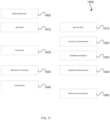
- FIG. 16 is an embodiment of a method 1800 for wireless communications in a conveyor system.
- the conveyor controller provides additional information to the track wireless hub to allow for a more direct connection to the pallet wireless hubs (sometimes called a "simplified handshake") that allows for fast connection to pallet wireless hubs that are entering the wireless zone of the track wireless hub.
- the method begins with the conveyor controller monitoring and controlling movement of the moving elements at 1805.
- the conveyor controller monitors the predetermined ID, location, motion, and other parameters related to the moving elements.
- the moving elements may be monitored using various types of tracking and sensing systems. For example, encoder strips, accelerometers, vision systems, and the like.
- the conveyor controller determines that a moving element is about to enter a wireless zone, at 1810, the conveyor controller provides the track wireless hub with the predetermined ID of the moving element, the predetermined ID of the pallet wireless hub associated with that moving element, or other information that may assist with quickly establishing communications.
- the predetermined ID/information may include various unique identifiers (or at least unique within the wireless environment) used in wireless communications such as a media access control (MAC) address, IP address, or the like that can be used to aid in faster connection with the pallet wireless hub.
- the data can be provided to the track wireless hub from the conveyor controller via a high-speed, for example, wired, communications link so that the track wireless hub can receive the information in real time or near real time.
- a wireless zone may have a primary zone, in which wireless operations are conducted, and a secondary zone, which acts as a "buffer" allowing communications between a track wireless hub (and thereby a conveyor controller) and a pallet wireless hub to commence before operations by an accessory on the moving element are required.
- the size of a secondary zone can be determined based on moving element movement capabilities (speed, acceleration and the like) to allow for communications to commence before a moving element enters a primary zone, even when the moving element is moving.
- the track wireless hub uses the predetermined ID/information to perform a direct connection (i.e. a simplified handshake) with the pallet wireless hub at 1815.
- the simplified handshake may be a new message directed at a particular pallet wireless hub (because the pallet wireless hub ID will be known) and including instructions that can be quickly acknowledged by the pallet wireless hub, while implementing the instructions.
- the simplified handshake may be a simple "ping" (including the pallet wireless hub ID) and a related simple acknowledgment from the pallet wireless hub to determine that the pallet wireless hub is receiving the signal.
- the response may be a message with the heartbeat signal noted above.
- wireless communications between the track wireless hub and the pallet wireless hub continue at 1820, using, for example, the concise communication format/protocol described herein.
- the communications allow for the transfer of instructions, data, feedback, and the like between the conveyor controller and accessory(ies) or the like on the moving element.
- the conveyor controller can also monitor for when a moving element is going to be leaving the wireless zone, at 1825. Prior to the moving element leaving the zone, the conveyor controller can optionally send any final commands, at 1830, to the accessory via the track and pallet wireless hubs. Final commands could include a lock command to control how the accessory will act when out of contact with a track wireless hub, for example, causing the accessory to stop movement, continue operating in the same way, perform one or more operations for a predetermined period of time or number of operations, remain in or move between various states, or the like.
- the conveyor controller Just prior to exiting the wireless zone, the conveyor controller notifies the track wireless hub, at 1835, and the track wireless hub can terminate communications with the pallet wireless hub to open up bandwidth for other pallet wireless hubs.
- FIG. 17 illustrates an embodiment of a timeline 1900 for wireless communication in a conveyor.
- Fig. 17 illustrates the operations of the conveyor controller and the track wireless hub.
- the conveyor controller determines that a moving element is approaching a wireless zone.
- the conveyor controller sends data related to the moving element (for example, ID sufficient to uniquely identify the pallet wireless hub on the moving element for communications) to the track wireless hub. It will be understood that the data may be for the pallet wireless hub itself or for the moving element and a look-up table or the like can be used to co-relate to the pallet wireless hub.
- the track wireless hub receives the data related to the moving element and then sets up for communication with the pallet wireless hub associated with the moving element at 1920.
- the conveyor controller notifies the track wireless hub that the moving element enters the zone. Simultaneous or shortly after entry the track wireless hub performs the direct connection/simplified handshake with the pallet wireless hub at 1930. It is intended that the track wireless hub will establish communications with the pallet wireless hub within approximately 0.1 second, which would be, for example, a distance of 0.4m at 4 m/sec on a linear motor track. In this way, the size of a secondary zone can be determined to allow for communications to commence before a moving element enters a primary zone.
- the conveyor controller sends operations commands via the track wireless hub, which conducts on-going communications with the pallet wireless hub at 1940.
- the conveyor controller then notifies the track wireless hub when the moving element is leaving the wireless zone.
- the track wireless hub releases communications with the pallet wireless hub. As noted above, there may also be any final operations commands sent prior to leaving the wireless zone.
- the conveyor controller may not know the locations of the moving elements or their identification.
- either the conveyor controller may obtain identification and location information in a conventional manner or the track wireless hub can perform a more detailed handshake procedure to determine the moving element IDs and communicate that to the conveyor controller, which can then determine location information.
- the conveyor controller can assist with transition between zones by providing moving element location and identification such that handoff between track wireless hubs can be timed to occur in an orderly fashion.
- the conveyor controller can communicate with each track wireless hub when the moving element will be leaving one wireless zone and entering the other as outlined above, if necessary, with a small difference in timing (such as, for example, .1s, .01s, .05s or the like) between the release of communications with one track wireless hub and the simplified handshake with the other track wireless hub.
- wireless zones may be able to assist with moving element identification and/or tracking, in particular at start-up or upon the addition of a new moving element being added to the conveyor system.
- the conveyor controller may need to move the moving elements to determine their location (i.e. move the moving elements enough that they interact with sensors on the track to identify location).
- this movement may not provide an actual identification of which moving element is which (for example, if the moving element sensor system does not include moving element ID).
- the track wireless hub(s) could perform conventional handshaking with pallet wireless hubs in the wireless zone(s), the conveyor controller could then individually vibrate the moving elements, and then, based on accelerometer data and unique identifier for the pallet wireless hub (or the like) from the moving element received via the pallet and track wireless hubs, the conveyor controller can identify the ID for each of the moving elements.
- moving elements, pallets, accessories, or the like would need an accelerometer.
- This type of system could be useful in cases where, for example, there is only one or a limited number of moving element ID readers on the conveyor system and the conveyor controller would otherwise need to move each moving element past an ID reader before conveyor operations and/or wireless communications could begin.
- This technique of conventional handshake with accelerometer data to provide moving element ID can also be applied to identify new pallets added to the conveyor system and/or for exception handling/fault recovery or re-initialization.
- two moving elements may be entering a zone at the same time or back-to-back.
- the conveyor controller can control the movement of each moving element so that there is time to do the direct/simplified handshake and make sure that wireless communications can begin for each moving element at the appropriate timing.
- wireless zones may be used for monitoring for errors or faults in operation.
- the track wireless hub can keep the conveyor controller updated with the number of moving elements the track wireless hub is currently communicating with in its zone. Since the conveyor controller is also monitoring all pallets in the zone, it can detect if there is a discrepancy between the number of pallets it expects are in the zone with the number the track wireless hub is reporting. If there is a discrepancy, the system can perform a recovery or re-initialization sequence, for example, of the types described above.
- a conveyor controller tries to communicate with a pallet wireless hub that a track wireless hub has not established communication with, the system can detect this fault condition and perform an appropriate recovery or re-initialization sequence of the type described above. In some cases, these fault recovery sequences can use a more conventional handshake to detect pallet wireless hubs (moving elements) in a wireless zone.
- Embodiments of the disclosure can be represented as a computer program product stored in a machine-readable medium (also referred to as a computer-readable medium, a processor-readable medium, or a computer usable medium having a computer-readable program code embodied therein).
- the machine-readable medium can be any suitable tangible, non-transitory medium, including magnetic, optical, or electrical storage medium including a diskette, compact disk read only memory (CD-ROM), memory device (volatile or non-volatile), or similar storage mechanism.
- the machine-readable medium can contain various sets of instructions, code sequences, configuration information, or other data, which, when executed, cause a processor to perform steps in a method according to an embodiment of the disclosure.
Landscapes
- Engineering & Computer Science (AREA)
- Computer Networks & Wireless Communication (AREA)
- Signal Processing (AREA)
- Non-Mechanical Conveyors (AREA)
- Control Of Conveyors (AREA)
Applications Claiming Priority (1)
| Application Number | Priority Date | Filing Date | Title |
|---|---|---|---|
| US202363601916P | 2023-11-22 | 2023-11-22 |
Publications (2)
| Publication Number | Publication Date |
|---|---|
| EP4572345A2 true EP4572345A2 (de) | 2025-06-18 |
| EP4572345A3 EP4572345A3 (de) | 2025-09-03 |
Family
ID=93648220
Family Applications (1)
| Application Number | Title | Priority Date | Filing Date |
|---|---|---|---|
| EP24214609.0A Pending EP4572345A3 (de) | 2023-11-22 | 2024-11-21 | Verfahren und system zur drahtlosen kommunikation in einem fördersystem |
Country Status (2)
| Country | Link |
|---|---|
| US (1) | US20250168817A1 (de) |
| EP (1) | EP4572345A3 (de) |
Citations (2)
| Publication number | Priority date | Publication date | Assignee | Title |
|---|---|---|---|---|
| US8397896B2 (en) | 2009-03-03 | 2013-03-19 | Ats Automation Tooling Systems Inc. | Multi-mode and multi-pitch conveyor system |
| US10300793B2 (en) | 2010-07-29 | 2019-05-28 | Ats Automation Tooling Systems Inc. | System and method for providing power to a moving element |
Family Cites Families (3)
| Publication number | Priority date | Publication date | Assignee | Title |
|---|---|---|---|---|
| US8018324B2 (en) * | 2006-03-17 | 2011-09-13 | Rockwell Automation Technologies, Inc. | Sight-line non contact coupled wireless technology |
| DE102020107783A1 (de) * | 2020-03-20 | 2021-09-23 | Beckhoff Automation Gmbh | Datenübertragung in einem linearen Transportsystem |
| EP4071970A1 (de) * | 2021-03-31 | 2022-10-12 | ATS Automation Tooling Systems Inc. | Verfahren und system zur drahtlosen kommunikation in einem fördersystem |
-
2024
- 2024-11-21 EP EP24214609.0A patent/EP4572345A3/de active Pending
- 2024-11-21 US US18/954,856 patent/US20250168817A1/en active Pending
Patent Citations (2)
| Publication number | Priority date | Publication date | Assignee | Title |
|---|---|---|---|---|
| US8397896B2 (en) | 2009-03-03 | 2013-03-19 | Ats Automation Tooling Systems Inc. | Multi-mode and multi-pitch conveyor system |
| US10300793B2 (en) | 2010-07-29 | 2019-05-28 | Ats Automation Tooling Systems Inc. | System and method for providing power to a moving element |
Also Published As
| Publication number | Publication date |
|---|---|
| US20250168817A1 (en) | 2025-05-22 |
| EP4572345A3 (de) | 2025-09-03 |
Similar Documents
| Publication | Publication Date | Title |
|---|---|---|
| US11701786B2 (en) | Robotic devices and methods for fabrication, use and control of same | |
| US10965201B2 (en) | Transport system, processing system and manufacturing method of article | |
| US10310513B2 (en) | Conveyance control device and merging point passing method for carrying cart | |
| US9224628B2 (en) | Reduced capacity carrier, transport, load port, buffer system | |
| JP3469652B2 (ja) | 電子部品装着装置 | |
| US20230015917A1 (en) | Data transmission in a linear transport system | |
| US20240217749A1 (en) | Energy transmission in a linear transport system | |
| US12397999B2 (en) | Method and system for wireless communication in a conveyor system | |
| CN100481365C (zh) | 用于传送提升组件的方法和装置 | |
| EP4572345A2 (de) | Verfahren und system zur drahtlosen kommunikation in einem fördersystem | |
| JP2019062614A (ja) | 搬送システム及び加工システム | |
| Farné et al. | IIoT based efficiency optimization in logistics applications | |
| JPS6254685A (ja) | 走行形腕ロボツトの駆動制御方法 | |
| CN211003304U (zh) | 传输变向装置和系统 | |
| US11994849B2 (en) | Machine to machine communications | |
| EP4537168A1 (de) | Konnektivitätsgeführte steuerung eines industriesystems | |
| CN117894726B (zh) | 自动化物料搬运系统 | |
| TWM570304U (zh) | Automatic guided vehicle and automatic guided vehicle system | |
| WO2025205104A1 (ja) | 搬送システム及び搬送方法 | |
| CN120802756A (zh) | 双伺服驱动器及其方法 | |
| WO2022090429A1 (en) | A system and a method for assembling a packaging | |
| CN112456065A (zh) | 传输变向装置、系统和方法 | |
| WO2018020672A1 (ja) | 互いに干渉領域を有する複数の機器の制御方法及び制御装置 |
Legal Events
| Date | Code | Title | Description |
|---|---|---|---|
| PUAI | Public reference made under article 153(3) epc to a published international application that has entered the european phase |
Free format text: ORIGINAL CODE: 0009012 |
|
| STAA | Information on the status of an ep patent application or granted ep patent |
Free format text: STATUS: THE APPLICATION HAS BEEN PUBLISHED |
|
| AK | Designated contracting states |
Kind code of ref document: A2 Designated state(s): AL AT BE BG CH CY CZ DE DK EE ES FI FR GB GR HR HU IE IS IT LI LT LU LV MC ME MK MT NL NO PL PT RO RS SE SI SK SM TR |
|
| PUAL | Search report despatched |
Free format text: ORIGINAL CODE: 0009013 |
|
| AK | Designated contracting states |
Kind code of ref document: A3 Designated state(s): AL AT BE BG CH CY CZ DE DK EE ES FI FR GB GR HR HU IE IS IT LI LT LU LV MC ME MK MT NL NO PL PT RO RS SE SI SK SM TR |
|
| RIC1 | Information provided on ipc code assigned before grant |
Ipc: H04W 4/021 20180101AFI20250729BHEP Ipc: B65G 43/00 20060101ALI20250729BHEP |