EP4571375A1 - Multicore fiber, optical device, and multicore fiber assembly - Google Patents
Multicore fiber, optical device, and multicore fiber assembly Download PDFInfo
- Publication number
- EP4571375A1 EP4571375A1 EP23852218.9A EP23852218A EP4571375A1 EP 4571375 A1 EP4571375 A1 EP 4571375A1 EP 23852218 A EP23852218 A EP 23852218A EP 4571375 A1 EP4571375 A1 EP 4571375A1
- Authority
- EP
- European Patent Office
- Prior art keywords
- core
- end surface
- cores
- core fiber
- fiber
- Prior art date
- Legal status (The legal status is an assumption and is not a legal conclusion. Google has not performed a legal analysis and makes no representation as to the accuracy of the status listed.)
- Pending
Links
Images




Classifications
-
- G—PHYSICS
- G02—OPTICS
- G02B—OPTICAL ELEMENTS, SYSTEMS OR APPARATUS
- G02B6/00—Light guides; Structural details of arrangements comprising light guides and other optical elements, e.g. couplings
- G02B6/24—Coupling light guides
- G02B6/26—Optical coupling means
- G02B6/262—Optical details of coupling light into, or out of, or between fibre ends, e.g. special fibre end shapes or associated optical elements
-
- G—PHYSICS
- G02—OPTICS
- G02B—OPTICAL ELEMENTS, SYSTEMS OR APPARATUS
- G02B6/00—Light guides; Structural details of arrangements comprising light guides and other optical elements, e.g. couplings
- G02B6/24—Coupling light guides
- G02B6/255—Splicing of light guides, e.g. by fusion or bonding
- G02B6/2555—Alignment or adjustment devices for aligning prior to splicing
-
- G—PHYSICS
- G02—OPTICS
- G02B—OPTICAL ELEMENTS, SYSTEMS OR APPARATUS
- G02B6/00—Light guides; Structural details of arrangements comprising light guides and other optical elements, e.g. couplings
- G02B6/02—Optical fibres with cladding with or without a coating
- G02B6/02042—Multicore optical fibres
-
- G—PHYSICS
- G02—OPTICS
- G02B—OPTICAL ELEMENTS, SYSTEMS OR APPARATUS
- G02B6/00—Light guides; Structural details of arrangements comprising light guides and other optical elements, e.g. couplings
- G02B6/04—Light guides; Structural details of arrangements comprising light guides and other optical elements, e.g. couplings formed by bundles of fibres
Definitions
- the present invention relates to a multi-core fiber, an optical device including a multi-core fiber, or a multi-core fiber assembly including multi-core fibers.
- a multi-core fiber including a plurality of cores is widely used.
- a document disclosing the multi-core fiber is, for example, Patent Literature 1.
- Patent Literature 1 Japanese Patent Application Publication, Tokukai, No. 2019-152866
- Optical fibers are often designed to have an end surface inclined such that the end surface is not orthogonal to an extending direction of cores, for the purpose of reducing reflection in the end surface.
- the following problem can occur, for example.
- An aspect of the present invention was made in consideration of the above problem, and has an object to provide a multi-core fiber having an end surface whose inclination direction is appropriately set in consideration of connection, an optical device including such a multi-core fiber, or a multi-core fiber assembly including such multi-core fibers.
- a multi-core fiber in accordance with an aspect of the present invention employs a configuration of a multi-core fiber including: a cladding; a plurality of cores formed inside the cladding; and a first end surface and a second end surface each of which is inclined so as not to be orthogonal to an extending direction of the plurality of cores, inclination directions of the first end surface and the second end surface being set so that, in a case where the first end surface and the second end surface are brought into surface contact with each other so as to minimize an angle made by an extending direction of the plurality of cores in the first end surface and an extending direction of the plurality of cores in the second end surface, each of the plurality of cores in the first end surface at least partially overlaps any of the plurality of cores in the second end surface.
- a multi-core fiber assembly in accordance with an aspect of the present invention employs a configuration of a multi-core fiber assembly including at least one first multi-core fiber and at least one second multi-core fiber, the at least one first multi-core fiber including a cladding, a plurality of cores formed inside the cladding, and a first end surface inclined so as not to be orthogonal to an extending direction of the plurality of cores, the at least one second multi-core fiber including a cladding, a plurality of cores formed inside the cladding, and a second end surface inclined so as not to be orthogonal to an extending direction of the plurality of cores, inclination directions of the first end surface and the second end surface being set so that, in a case where the first end surface and the second end surface are brought into surface contact with each other so as to minimize an angle made by the extending direction of the plurality of cores in the first end surface and the extending direction of the plurality of cores in the second end surface, each of the plurality of core
- a multi-core fiber having an end surface whose inclination direction is appropriately set in consideration of connection, an optical device including such a multi-core fiber, or a multi-core fiber assembly including such multi-core fibers.
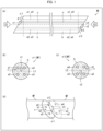
- FIG. 1 a configuration of a multi-core fiber MF in accordance with a first embodiment of the present invention.
- a is a side view of the multi-core fiber MF.
- (b) is a front view of one end surface (hereinafter, referred to as a "first end surface”) ⁇ 1 of the multi-core fiber MF viewed in a direction of a sight line E1.
- (c) is a front view of the other end surface (hereinafter, referred to as a "second end surface”) ⁇ 2 of the multi-core fiber MF viewed in a direction of a sight line E2.
- d is a perspective view of the multi-core fiber MF which is in a state where a first end surface ⁇ 1 and a second end surface ⁇ 2 abut on each other.
- the multi-core fiber MF includes n cores a1 to an and a cladding b.
- the cladding b is a cylindrical member.
- the cladding b is made of silica glass, for example.
- Each core ai (i is a natural number of not less than 1 and not more than n) is a cylindrical area which is provided inside the cladding b, which has a refractive index higher than that of the cladding b, and which extends in a direction in which the cladding b extends.
- Each core ai is made of silica glass doped with an updopant such as germanium, for example.
- the cladding b may have any shape, provided that the shape is a columnar shape. Further, the cladding b may have any cross-sectional shape. The cross-sectional shape of the cladding b may be a polygonal shape, such as a quadrangular shape or a hexagonal shape.
- the multi-core fiber MF may further include an additional core(s) which is/are not the n cores a1 to an of interest in the present embodiment.
- the multi-core fiber MF may include, as an additional core(s) which is/are not the n cores a1 to an of interest, a core provided in a center of the cladding b.
- the n cores a1 to an of interest are cores used for communication, for example.
- the n cores a1 to an of interest are preferably cores satisfying the standard defined by ITU-T.
- the additional core(s) which is/are not the n cores a1 to an of interest may be a core(s) used for communication or a core(s) (dummy core(s)) not used for communication. In the latter case, the additional core(s) which is/are not the n cores a1 to an of interest may be cores not satisfying the standard defined by ITU-T.
- the multi-core fiber MF further includes a marker c for identifying core numbers 1 to n of the cores a1 to an.
- the marker c is a columnar area which is provided inside the cladding b, which has a different refractive index from that of the cladding b, and which extends in a direction in which the cladding b extends.
- the marker c may have any cross-sectional shape.
- the cross-sectional shape of the marker c may be a circular shape, a triangular shape, or a quadrangular shape, for example.
- the marker c is made of silica glass doped with a downdopant such as fluorine or boron, for example.
- the refractive index of the marker c is lower than that of the cladding b.
- the marker c is made of silica glass doped with an updopant such as germanium, aluminum, phosphor, or chlorine. In this case, the refractive index of the marker c is higher than that of the cladding b.
- the marker c may be formed by, for example, a drilling process or a stack-and-draw process. Generally, the marker c has an outer diameter smaller than an outer diameter of the core ai. Note that the marker c may be a hole. In this case, the refractive index of the marker c is lower than that of the cladding b.
- the multi-core fiber MF may further include a marker which is not the marker c of interest in the present embodiment.
- the core numbers 1 to n of the cores a1 to an can be identified on the basis of distances from the marker c. For example, in a case where the cores a1 to an are arranged on a circumference of a circle, the core numbers 1 to n of the cores a1 to an can be identified in the following manner. First, the core a1, which is closest to the marker c, is given a core number "1". Next, the core a2, which is second closest to the marker c, is given a core number "2".
- the core a3 which is a third core to be traced is given a core number "3”
- the core a4 which is a fourth core to be traced is given a core number "4"
- the core an which is an n-th core to be traced is given a core number "n”.
- the present embodiment employs a configuration in which the core numbers 1 to n are identified by referring to the marker c.
- a structure to be referred to for identifying the core numbers 1 to n is not limited to the marker c.
- the core numbers 1 to n may be identified by referring to a mark formed on a surface of the cover.
- the core numbers 1 to n are identified by referring to a key (e.g., a projection) formed in the connector.
- a key e.g., a projection
- the core numbers 1 to n may be identified by referring to the flat portion.
- the core numbers 1 to n may be identified by referring to the cutout.
- the first end surface ⁇ 1 is inclined so as not to be orthogonal to an extending direction of the cores a1 to an.
- a flat plane orthogonal to the extending direction of the cores a1 to an is a horizontal plane
- a direction in which a falling gradient of the first end surface ⁇ 1 becomes maximum will be referred to as an inclination direction v1 of the first end surface ⁇ 1
- a maximum value of the falling gradient of the first end surface ⁇ 1 will be referred to as an inclination angle ⁇ 1 of the first end surface ⁇ 1.
- the inclination angle ⁇ 1 of the first end surface ⁇ 1 is preferably not less than 2° and not more than 88°, more preferably not less than 4° and not more than 12°, even more preferably not less than 7° and not more than 9°, still more preferably not less than 7.8° and not more than 8.2°.
- the inclination angle ⁇ 1 of the first end surface ⁇ 1 is 8° or 6°, for example. Note that a gradient in a non-inclination direction is preferably not less than 0° and not more than 2°, more preferably not less than 0° and not more than 1°.
- the second end surface ⁇ 2 is inclined so as not to be orthogonal to the extending direction of the cores a1 to an.
- the flat plane orthogonal to the extending direction of the cores a1 to an is a horizontal plane
- a direction in which a falling gradient of the second end surface ⁇ 2 becomes maximum will be referred to as an inclination direction v2 of the second end surface ⁇ 2
- a maximum value of the falling gradient of the second end surface ⁇ 2 will be referred to as an inclination angle ⁇ 2 of the second end surface ⁇ 2.
- the inclination angle ⁇ 2 of the second end surface ⁇ 2 is preferably not less than 2° and not more than 88°, more preferably not less than 4° and not more than 12°, even more preferably not less than 7° and not more than 9°, still more preferably not less than 7.8° and not more than 8.2°.
- the inclination angle ⁇ 2 of the second end surface ⁇ 2 is 8° or 6°, for example. Note that the gradient in a non-inclination direction is preferably not less than 0° and not more than 2°, more preferably not less than 0° and not more than 1°.
- the inclination direction v1 of the first end surface ⁇ 1 and the inclination direction v2 of the second end surface ⁇ 2 are defined so as to satisfy the following condition 1.
- Condition 1 In a case where the first end surface ⁇ 1 and the second end surface ⁇ 2 are brought into surface contact with each other so as to minimize an angle made by the extending direction of the cores a1 to an in the first end surface ⁇ 1 and the extending direction of the cores a1 to an in the second end surface ⁇ 2, each of the cores a1 to an in the first end surface ⁇ 1 at least partially overlaps any of the cores a1 to an in the second end surface ⁇ 2.
- the aspect in which two cores at least partially overlap each other encompasses an aspect in which only a part of one core overlaps only a part of the other core, an aspect in which only a part of one core overlaps the whole of the other core, and an aspect in which the whole of one core overlaps the whole of the other core (i.e., an aspect in which the two cores overlap each other without excess or deficiency).
- the expression that the first end surface ⁇ 1 and the second end surface ⁇ 2 are connected to each other means that the first end surface ⁇ 1 and the second end surface ⁇ 2 are connected to each other "so as to minimize an angle made by an extending direction of the cores a1 to an in the first end surface ⁇ 1 of one multi-core fiber MF and an extending direction of the cores a1 to an in the second end surface ⁇ 2 of the other multi-core fiber".
- each of the inclination angle ⁇ 1 of the first end surface ⁇ 1 and the inclination angle ⁇ 2 of the second end surface ⁇ 2 is preferably not less than 45°, more preferably not less than 60°, even more preferably not less than 70°.
- the reason for this is as follows. Setting the inclination angles ⁇ 1 and ⁇ 2 so as to be larger can provide extreme turning made at a connection point between the two multi-core fibers MF when the cores a1 to an of the two multi-core fibers MF are not optically coupled to each other. This makes it easy to carry out self-alignment in connection of the two multi-core fibers MF.
- setting the inclination angles ⁇ 1 and ⁇ 2 can increase surface areas of the end surfaces ⁇ 1 and ⁇ 2. This makes it possible to make the surface contact between the end surfaces ⁇ 1 and ⁇ 2 more stable, thereby making it possible to provide firmer connection between the end surfaces ⁇ 1 and ⁇ 2.
- the inclination angle ⁇ 1 of the first end surface ⁇ 1 and the inclination angle ⁇ 2 of the second end surface ⁇ 2 may or may not be equal to each other.
- the inclination angle ⁇ 1 of the first end surface ⁇ 1 and the inclination angle ⁇ 2 of the second end surface ⁇ 2 are preferably equivalent to each other (substantially equal to each other), more preferably equal to each other (completely equal to each other).
- the expression that the inclination angle ⁇ 1 of the first end surface ⁇ 1 and the inclination angle ⁇ 2 of the second end surface ⁇ 2 are equivalent to each other (substantially equal to each other) means, for example, that a difference
- n ⁇ (n-1)/2 straight lines passing through centers of two cores ai and aj selected from the cores a1 to an in the first end surface ⁇ 1 and the second end surface ⁇ 2 will be considered.
- Each of the gradients of the first end surface ⁇ and the second end surface ⁇ 2 with respect to a direction which is in parallel with these straight lines is preferably not more than 5°, more preferably not more than 2°.
- a minimum value of an angle made by the extending direction of the cores a1 to an in the first end surface ⁇ 1 and the extending direction of the cores a1 to an in the second end surface ⁇ 2 is 0°.
- Condition 1' In a case where the first end surface ⁇ 1 and the second end surface ⁇ 2 are brought into surface contact with each other so as to make the extending direction of the cores a1 to an in the first end surface ⁇ 1 and the extending direction of the cores a1 to an in the second end surface ⁇ 2 coincide with each other, each of the cores a1 to an in the first end surface ⁇ 1 at least partially overlaps any of the cores a1 to an in the second end surface ⁇ 2.
- cores a1 to an of these two multi-core fibers MF can be optically coupled to each other.
- the expression that the first end surface ⁇ 1 and the second end surface ⁇ 2 are connected to each other such that "the two multi-core fibers MF are arranged on a single straight line” means that the first end surface ⁇ 1 and the second end surface ⁇ 2 are connected to each other such that "an extending direction of the cores a1 to an of the one multi-core fiber MF and an extending direction of the cores a1 to an of the other multi-core fiber MF coincide with each other".
- the multi-core fiber MF of the present embodiment it is defined that projections of the inclination direction v1 of the first end surface ⁇ 1 and the inclination direction v2 of the second end surface ⁇ 2 onto a flat plane orthogonal to an optical axis L0 extend in opposite directions.
- the multi-core fiber MF of the present embodiment satisfies, in addition to the above condition 1, the following condition 2.
- pairs of cores which at least partially overlap each other are (1) a pair of the core a1 in the first end surface ⁇ 1 and the core a1 in the second end surface ⁇ 2, (2) a pair of the core a2 in the first end surface ⁇ 1 and the core a2 in the second end surface ⁇ 2, (3) a pair of the core a3 in the first end surface ⁇ 1 and the core a3 in the second end surface ⁇ 2, and (4) a pair of the core a4 in the first end surface ⁇ 1 and the core a4 in the second end surface ⁇ 2. Also in any of the four pairs, two cores constituting the pair have the same core number.
- cores having the same core number can be optically coupled to each other.
- the cores a1 to an are arranged in a linearly symmetric manner (substantially linearly symmetrically) with respect to a virtual axis L1 orthogonal to the inclination direction v1.
- the expression that the cores a1 to an are arranged in a linearly symmetric manner with respect to the virtual axis L1 means that, in a case where the first end surface ⁇ 1 is inverted with respect to the virtual axis L1, each of the cores a1 to an at least partially overlaps any of the cores a1 to an.
- the virtual axis L1 is a straight line in the first end surface ⁇ 1 .
- the virtual axis L1 passes through a center of the first end surface ⁇ 1 (a center of the cladding). It is not essential that the virtual axis L1 pass through the center of the first end surface ⁇ 1, provided that the virtual axis L1 is orthogonal to the inclination direction v1.
- the cores a1 to an are more preferably arranged linearly symmetrically (completely linearly symmetrically) with respect to the virtual axis L1 orthogonal to the inclination direction v1.
- the expression that the cores a1 to an are arranged linearly symmetrically with respect to the virtual axis L1 means that, in a case where the first end surface ⁇ 1 is inverted with respect to the virtual axis L1, each of the cores a1 to an overlaps any of the cores a1 to an without excess or deficiency.
- a pair of cores which are linearly symmetric with respect to the virtual axis L1 are away from the virtual axis L1 by equal distances.
- the above-described virtual axis L1 does not cross any of the cores a1 to an.
- the multi-core fiber MF in accordance with the present embodiment is configured such that, in the second end surface ⁇ 2, the cores a1 to an are arranged in a linearly symmetric manner (substantially linearly symmetrically) with respect to a virtual axis L2 orthogonal to the inclination direction v2.
- the expression that the cores a1 to an are arranged in a linearly symmetric manner with respect to the virtual axis L2 means that, in a case where the second end surface ⁇ 2 is inverted with respect to the virtual axis L2, each of the cores a1 to an at least partially overlaps any of the cores a1 to an.
- the virtual axis L2 is a straight line in the second end surface ⁇ 2.
- the virtual axis L2 passes through a center of the second end surface ⁇ 2 (a center of the cladding). It is not essential that the virtual axis L2 pass through the center of the second end surface ⁇ 2, provided that the virtual axis L2 is orthogonal to the inclination direction v2.
- the cores a1 to an are more preferably arranged linearly symmetrically (completely linearly symmetrically) with respect to the virtual axis L2 orthogonal to the inclination direction v2.
- the expression that the cores a1 to an are arranged linearly symmetrically with respect to the virtual axis L2 means that, in a case where the second end surface ⁇ 2 is inverted with respect to the virtual axis L2, each of the cores a1 to an overlaps any of the cores a1 to an without excess or deficiency.
- a pair of cores which are linearly symmetric with respect to the virtual axis L2 are away from the virtual axis L2 by equal distances.
- the multi-core fiber MF in accordance with the present embodiment is configured such that, in the second end surface ⁇ 2, the above-described virtual axis L2 does not cross any of the cores a1 to an.
- cores having different core numbers are connected to each other.
- the core a1 of the one multi-core fiber MF is connected to the core a2 of the other multi-core fiber MF
- the core a3 of the one multi-core fiber MF is connected to the core a4 of the other multi-core fiber MF.
- the multi-core fiber MF shown in Fig. 1 is configured such that, in the first end surface ⁇ 1, the core a1 closest to the marker c and the core a2 second closest to the marker c are arranged so as to sandwich the virtual axis L1 therebetween.
- the marker c is disposed near the virtual axis L1. This makes it easy to observe the marker c together with the cores a1 to an, in a case where the first end surface ⁇ 1 of the multi-core fiber MF is observed from the front with use of a microscope or the like.
- the multi-core fiber MF shown in Fig. 1 is configured such that, in the second end surface ⁇ 2, the core a1 closest to the marker c and the core a2 second closest to the marker c are arranged so as to sandwich the virtual axis L2 therebetween.
- the marker c is disposed near the virtual axis L2. This makes it easy to observe the marker c together with the cores a1 to an, in a case where the second end surface ⁇ 2 of the multi-core fiber MF is observed from the front with use of a microscope or the like. This is because that, in a case where a focus of an objective lens is set on the virtual axis L2 in order to evenly suppress defocus of the cores a1 to an, the above arrangement can reduce defocus of the marker c.
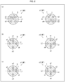
- FIG. 2 a first variation of the multi-core fiber MF in accordance with the first embodiment.
- Fig. 2 (a) is a front view of a first end surface ⁇ 1 and a second end surface ⁇ 2 of a multi-core fiber MF in accordance with the first variation.
- (b) is a front view of a first end surface ⁇ 1 and a second end surface ⁇ 2 of a multi-core fiber MF in accordance with a second variation.
- (c) is a front view of a first end surface ⁇ 1 and a second end surface ⁇ 2 of a multi-core fiber MF in accordance with a third variation.
- the multi-core fiber MF in accordance with the first variation is configured such that a virtual axis L1 does not cross any of cores a1 to an in the first end surface ⁇ 1.
- the multi-core fiber MF shown in Fig. 1 is configured such that the cores a1 and a2 are arranged side by side across the virtual axis L1 in the first end surface ⁇ 1
- the multi-core fiber MF in accordance with the first variation is configured such that the cores a1 and a4 are arranged side by side across the virtual axis L1 in the first end surface ⁇ 1. This also applies to the second end surface ⁇ 2.
- the core a1 of the one multi-core fiber MF is connected to the core a4 of the other multi-core fiber MF, and the core a2 of the one multi-core fiber MF is connected to the core a3 of the other multi-core fiber MF.
- the multi-core fiber MF in accordance with the second variation is configured such that a virtual axis L1 crosses cores a2 and a4 in the first end surface ⁇ 1. This also applies to the second end surface ⁇ 2.
- the core a2 of the one multi-core fiber MF is connected to the core a2 of the other multi-core fiber MF, and the core a4 of the one multi-core fiber MF is connected to the core a4 of the other multi-core fiber MF. This also applies to the second end surface ⁇ 2.
- the multi-core fiber MF shown in (b) of Fig. 2 is configured such that, in the first end surface ⁇ 1, the core a2 second closest to the marker c is disposed on the virtual axis L1.
- the marker c is disposed near the virtual axis L1. This makes it easy to observe the marker c together with the cores a1 to an, in a case where the first end surface ⁇ 1 of the multi-core fiber MF is observed from the front with use of a microscope or the like.
- This is because that, in a case where a focus of an objective lens is set on the virtual axis L1 in order to evenly suppress defocus of the cores a1 to an, the above arrangement can reduce defocus of the marker c.
- This also applies to multi-core fibers MF illustrated in (b) of Fig. 4 and (b) of Fig. 6 , which will be described later.
- the multi-core fiber MF in accordance with the third variation is configured such that a virtual axis L1 crosses cores a1 and a3 in the first end surface ⁇ 1. This also applies to the second end surface ⁇ 2.
- the core a1 of the one multi-core fiber MF is connected to the core a1 of the other multi-core fiber MF, and the core a3 of the one multi-core fiber MF is connected to the core a3 of the other multi-core fiber MF. This also applies to the second end surface ⁇ 2.
- the multi-core fiber MF shown in (c) of Fig. 2 is configured such that, in the first end surface ⁇ 1, the core a1 closest to the marker c is disposed on the virtual axis L1.
- the marker c is disposed near the virtual axis L1. This makes it easy to observe the marker c together with the cores a1 to an, in a case where the first end surface ⁇ 1 of the multi-core fiber MF is observed from the front with use of a microscope or the like.
- This is because that, in a case where a focus of an objective lens is set on the virtual axis L1 in order to evenly suppress defocus of the cores a1 to an, the above arrangement can reduce defocus of the marker c.
- This also applies to multi-core fibers MF illustrated in (c) of Fig. 4 and (c) of Fig. 6 , which will be described later.
- the multi-core fiber MF shown in (c) of Fig. 2 is configured such that, in the second end surface ⁇ 2, the core a1 closest to the marker c is disposed on the virtual axis L2.
- the marker c is disposed near the virtual axis L2. This makes it easy to observe the marker c together with the cores a1 to an, in a case where the second end surface ⁇ 2 of the multi-core fiber MF is observed from the front with use of a microscope or the like.
- the above arrangement can reduce defocus of the marker c.
- the multi-core fibers MF illustrated in Fig. 1 , (b) of Fig. 2, and (c) of Fig. 2 have, as a common characteristic, the following characteristic: "In the first end surface ⁇ 1, a center of the marker c is included in an area between the virtual axis L1 and a straight line which passes through a center of, among the cores a1 to an, a core farthest from the virtual axis L1 and which is in parallel with the virtual axis L1."
- the multi-core fiber MF illustrated in Fig. 1 has the following characteristic: "In the first end surface ⁇ 1, a center of the marker c is included in an area between the virtual axis L1 and a straight line which passes through a center of, among the cores a1 to an, a core closest to the virtual axis L1 and which is in parallel with the virtual axis L1.” Therefore, the center of the marker c is arranged so as to be even closer to the virtual axis L1.
- the multi-core fiber MF illustrated in (a) of Fig. 2, (b) of Fig. 2, and (c) of Fig. 2 the multi-core fiber MF illustrated in Fig.
- FIG. 3 a configuration of a multi-core fiber MF in accordance with a second embodiment of the present invention.
- a is a side view of the multi-core fiber MF.
- (b) is a front view of one end surface (hereinafter, referred to as a "first end surface”) ⁇ 1 of the multi-core fiber MF viewed in a direction of a sight line E1.
- (c) is a front view of the other end surface (hereinafter, referred to as a "second end surface”) ⁇ 2 of the multi-core fiber MF viewed in a direction of a sight line E2.
- d is a perspective view of the multi-core fiber MF which is in a state where a first end surface ⁇ 1 and a second end surface ⁇ 2 abut on each other.
- the multi-core fiber MF in accordance with the first embodiment it is defined that the projections of the inclination direction v1 of the first end surface ⁇ 1 and the inclination direction v2 of the second end surface ⁇ 2 onto the flat plane orthogonal to the optical axis L0 extend in opposite directions.
- projections of an inclination direction v1 of the first end surface ⁇ 1 and an inclination direction v2 of the second end surface ⁇ 2 onto a flat plane orthogonal to an optical axis L0 extend in the same direction.
- Condition 3 In a case where the first end surface ⁇ 1 and the second end surface ⁇ 2 are brought into surface contact with each other so as to minimize an angle made by an extending direction of cores a1 to an in the first end surface ⁇ 1 and an extending direction of cores a1 to an in the second end surface ⁇ 2, cores which at least partially overlap each other have different core numbers.
- pairs of cores which at least partially overlap each other are (1) a pair of the core a1 in the first end surface ⁇ 1 and the core a3 in the second end surface ⁇ 2, (2) a pair of the core a2 in the first end surface ⁇ 1 and the core a4 in the second end surface ⁇ 2, (3) a pair of the core a3 in the first end surface ⁇ 1 and the core a1 in the second end surface ⁇ 2, and (4) a pair of the core a4 in the first end surface ⁇ 1 and the core a2 in the second end surface ⁇ 2. Also in any of the four pairs, two cores constituting the pair have different core numbers.
- FIG. 4 a first variation of the multi-core fiber MF in accordance with the second embodiment.
- (a) is a front view of a first end surface ⁇ 1 and a second end surface ⁇ 2 of a multi-core fiber MF in accordance with the first variation.
- (b) is a front view of a first end surface ⁇ 1 and a second end surface ⁇ 2 of a multi-core fiber MF in accordance with a second variation.
- (c) is a front view of a first end surface ⁇ 1 and a second end surface ⁇ 2 of a multi-core fiber MF in accordance with a third variation.
- the three variations illustrated in Fig. 2 can be arranged for the multi-core fiber MF illustrated in Fig. 1
- the three variations illustrated in Fig. 4 can be arranged for the multi-core fiber MF illustrated in Fig. 3 .
- the effects achieved by the multi-core fibers MF in accordance with the variations illustrated in Fig. 4 are similar to the effects achieved by the multi-core fibers MF in accordance with the variations illustrated in Fig. 2 .
- FIG. 5 a configuration of a multi-core fiber MF in accordance with a third embodiment of the present invention.
- (a) is a side view of the multi-core fiber MF.
- (b) is a front view of one end surface (hereinafter, referred to as a "first end surface”) ⁇ 1 of the multi-core fiber MF viewed in a direction of a sight line E1.
- (c) is a front view of the other end surface (hereinafter, referred to as a "second end surface”) ⁇ 2 of the multi-core fiber MF viewed in a direction of a sight line E2.
- (d) is a perspective view of the multi-core fiber MF which is in a state where a first end surface ⁇ 1 and a second end surface ⁇ 2 abut on each other.
- the multi-core fiber MF in accordance with the first embodiment it is defined that the projections of the inclination direction v1 of the first end surface ⁇ 1 and the inclination direction v2 of the second end surface ⁇ 2 onto the flat plane orthogonal to the optical axis L0 extend in opposite directions.
- projections of an inclination direction v1 of the first end surface ⁇ 1 and an inclination direction v2 of the second end surface ⁇ 2 onto a flat plane orthogonal to an optical axis L0 are orthogonal to each other.
- Condition 3 In a case where the first end surface ⁇ 1 and the second end surface ⁇ 2 are brought into surface contact with each other so as to minimize an angle made by an extending direction of cores a1 to an in the first end surface ⁇ 1 and an extending direction of cores a1 to an in the second end surface ⁇ 2, cores which at least partially overlap each other have different core numbers.
- pairs of cores which at least partially overlap each other are (1) a pair of the core a1 in the first end surface ⁇ 1 and the core a2 in the second end surface ⁇ 2, (2) a pair of the core a2 in the first end surface ⁇ 1 and the core a3 in the second end surface ⁇ 2, (3) a pair of the core a3 in the first end surface ⁇ 1 and the core a4 in the second end surface ⁇ 2, and (4) a pair of the core a4 in the first end surface ⁇ 1 and the core a1 in the second end surface ⁇ 2. Also in any of the four pairs, two cores constituting the pair have different core numbers.
- FIG. 6 is a front view of a first end surface ⁇ 1 and a second end surface ⁇ 2 of a multi-core fiber MF in accordance with a first variation.
- (b) is a front view of a first end surface ⁇ 1 and a second end surface ⁇ 2 of a multi-core fiber MF in accordance with a second variation.
- (c) is a front view of a first end surface ⁇ 1 and a second end surface ⁇ 2 of a multi-core fiber MF in accordance with a third variation.
- the three variations illustrated in Fig. 2 can be arranged for the multi-core fiber MF illustrated in Fig. 1
- the three variations illustrated in Fig. 6 can be arranged for the multi-core fiber MF illustrated in Fig. 5 .
- the effects achieved by the multi-core fibers MF in accordance with the variations illustrated in Fig. 6 are similar to the effects achieved by the multi-core fibers MF in accordance with the variations illustrated in Fig. 2 .
- FIG. 7 a configuration of a multi-core fiber MF in accordance with a fourth embodiment of the present invention.
- (a) is a side view of the multi-core fiber MF.
- (b) is a front view of one end surface (hereinafter, referred to as a "first end surface”) ⁇ 1 of the multi-core fiber MF viewed in a direction of a sight line E1.
- (c) is a front view of the other end surface (hereinafter, referred to as a "second end surface”) ⁇ 2 of the multi-core fiber MF viewed in a direction of a sight line E2.
- (d) is a perspective view of the multi-core fiber MF which is in a state where a first end surface ⁇ 1 and a second end surface ⁇ 2 abut on each other.
- the multi-core fiber MF in accordance with the first embodiment it is defined that the projections of the inclination direction v1 of the first end surface ⁇ 1 and the inclination direction v2 of the second end surface ⁇ 2 onto the flat plane orthogonal to the optical axis L0 extend in opposite directions.
- projections of an inclination direction v1 of the first end surface ⁇ 1 and an inclination direction v2 of the second end surface ⁇ 2 onto a flat plane orthogonal to an optical axis L0 are orthogonal to each other.
- Condition 3 In a case where the first end surface ⁇ 1 and the second end surface ⁇ 2 are brought into surface contact with each other so as to minimize an angle made by an extending direction of cores a1 to an in the first end surface ⁇ 1 and an extending direction of cores a1 to an in the second end surface ⁇ 2, cores which at least partially overlap each other have different core numbers.
- pairs of cores which at least partially overlap each other are (1) a pair of the core a1 in the first end surface ⁇ 1 and the core a4 in the second end surface ⁇ 2, (2) a pair of the core a2 in the first end surface ⁇ 1 and the core a1 in the second end surface ⁇ 2, (3) a pair of the core a3 in the first end surface ⁇ 1 and the core a2 in the second end surface ⁇ 2, and (4) a pair of the core a4 in the first end surface ⁇ 1 and the core a3 in the second end surface ⁇ 2. Also in any of the four pairs, two cores constituting the pair have different core numbers.
- FIG. 8 is a front view of a first end surface ⁇ 1 and a second end surface ⁇ 2 of a multi-core fiber MF in accordance with a first variation.
- (b) is a front view of a first end surface ⁇ 1 and a second end surface ⁇ 2 of a multi-core fiber MF in accordance with a second variation.
- (c) is a front view of a first end surface ⁇ 1 and a second end surface ⁇ 2 of a multi-core fiber MF in accordance with a third variation.
- the three variations illustrated in Fig. 2 can be arranged for the multi-core fiber MF illustrated in Fig. 1
- the three variations illustrated in Fig. 8 can be arranged for the multi-core fiber MF illustrated in Fig. 7 .
- the effects achieved by the multi-core fibers MF in accordance with the variations illustrated in Fig. 8 are similar to the effects achieved by the multi-core fibers MF in accordance with the variations illustrated in Fig. 2 .
- the multi-core fiber MF is a multi-core fiber not including a connection point, that is, a multi-core fiber in which a marker c is continuous from a first end surface ⁇ 1 to a second end surface ⁇ 2.
- the present invention is not limited to this. That is, the present invention encompasses a multi-core fiber including at least one connection point, that is, a multi-core fiber in which a marker c is not continuous from a first end surface ⁇ 1 to a second end surface ⁇ 2.
- two multi-core fibers MF are prepared, and then a first end surface ⁇ 1 of one multi-core fiber MF and a first end surface ⁇ 1 of the other multi-core fiber MF are connected to each other.
- This can provide a multi-core fiber whose both end surfaces are second end surfaces ⁇ 2.
- the first end surfaces ⁇ 1 of the multi-core fibers MF may or may not be inclined.
- two multi-core fibers MF are prepared, and then a second end surface ⁇ 2 of one multi-core fiber MF and a second end surface ⁇ 2 of the other multi-core fiber MF are connected to each other. This can provide a multi-core fiber whose both ends are first end surfaces ⁇ 1.
- the second end surfaces ⁇ 2 of the multi-core fibers MF may or may not be inclined.
- the multi-core fibers obtained in this manner can also be encompassed in the present invention, provided that these multi-core fibers satisfy the above-described condition 1.
- the following mode can be achieved in each of such multi-core fibers. That is, among sets of cores at least partially overlapping each other, some sets are each constituted by cores having the same core number and the other sets are each constituted by cores having different core numbers.
- FIG. 9 a configuration of an optical device OD1 in accordance with a fifth embodiment of the present invention.
- (a) is a side view of the optical device OD1.
- (b) is a front view of one end surface of the optical device OD1 viewed in a direction of a sight line E1.
- (c) is a front view of the other end surface of the optical device OD1 viewed in a direction of a sight line E2.
- the optical device OD1 includes a multi-core fiber MF and single-core connectors C1 and C2 provided to both ends of the multi-core fiber MF.
- the multi-core fiber MF may be any of the multi-core fibers MF illustrated in Figs. 1 to 8 . Illustrated as the multi-core fiber MF in Fig. 9 is the multi-core fiber MF illustrated in Fig. 1 .
- the first single-core connector C1 is provided at one of the ends of the multi-core fiber MF.
- An end surface of the first single-core connector C1 is inclined so as to be flush with the first end surface ⁇ 1 of the multi-core fiber MF.
- a side surface which lays ahead in the inclination direction v1 of the first end surface ⁇ 1 is provided with a key K1.
- the key K1 is, for example, a rectangular parallelepiped projection protruding from the side surface of the first single-core connector C1.
- the second single-core connector C2 is provided at the other of the ends of the multi-core fiber MF.
- An end surface of the second single-core connector C2 is inclined so as to be flush with the second end surface ⁇ 2 of the multi-core fiber MF.
- a side surface which lays ahead in the inclination direction v2 of the second end surface ⁇ 2 is provided with a key K2.
- the key K2 is, for example, a rectangular parallelepiped projection protruding from the side surface of the second single-core connector C2.
- the present invention is not limited to this. That is, the present invention also encompasses a configuration in which a single-core connector is provided to one end of a multi-core fiber MF. That is, the present invention also encompasses a configuration achieved by omitting, from the optical device OD1 illustrated in Fig. 9 , one of the first single-core connector C1 and the second single-core connector C2. In this case, an end surface of the multi-core fiber MF which end surface is not provided with a single-core connector may or may not be inclined.
- the multi-core fiber MF may be a multi-core fiber 103 constituting a Fan-In/Fan-Out (FI/FO) device FD1, as shown in (a) of Fig. 14 .
- the FI/FO device FD1 includes an optical path conversion section 101 having an optical path conversion function, a multi-core fiber 103 provided to one side of the optical path conversion section, and a plurality of single-core fibers 102a to 102d provided to the other side of the optical path conversion section.
- the number of single-core fibers 102a to 102d corresponds to the number of cores in the multi-core fiber 103.
- the number of single-core fibers 102a to 102d is equal to the number of cores in the multi-core fiber.
- the end surface of the multi-core fiber MF which end surface is not provided with the single-core connector may be connected to a multi-core fiber 103 (which may sometimes be called a "pig-tail fiber") constituting a FI/FO device FD2, as shown in (b) of Fig. 14 .
- a multi-core fiber 103 which may sometimes be called a "pig-tail fiber" constituting a FI/FO device FD2
- edge reflection which may otherwise be caused by an end surface of the multi-core fiber MF and an end surface of the optical path conversion section 101, which can make port number management in the optical path conversion section easier.
- FIG. 10 a configuration of an optical device OD2 in accordance with a sixth embodiment of the present invention.
- (a) is a side view of the optical device OD2.
- (b) is a front view of one end surface of the optical device OD2 viewed in a direction of a sight line E1.
- (c) is a front view of the other end surface of the optical device OD2 viewed in a direction of a sight line E2.
- the optical device OD2 includes a multi-core fiber bundle MFB constituted by a plurality of multi-core fibers MF and multi-core connectors C3 and C4 provided to both ends of the multi-core fiber bundle MFB.
- each of the multi-core fibers MF constituting the multi-core fiber MFB in Fig. 10 Illustrated as each of the multi-core fibers MF constituting the multi-core fiber MFB in Fig. 10 is the multi-core fiber MF shown in Fig. 1 .
- each of the multi-core fibers MF constituting the multi-core fiber bundle MFB may be any one of the multi-core fibers MF shown in Figs. 1 to 8 .
- each of the multi-core fibers MF constituting the multi-core fiber bundle MFB may be the multi-core fiber MF illustrated in (b) of Fig. 2 or the multi-core fiber MF illustrated in (c) of Fig. 2 .
- the first multi-core connector C3 is provided at one end of the multi-core fiber bundle MFB.
- the multi-core fibers MF constituting the multi-core fiber bundle MFB are fixed to the first multi-core connector C3 such that (i) end surfaces (first end surfaces ⁇ 1 in the example shown in Fig. 10 ) which end surfaces are closer to the first multi-core connector C3 are all inclined in a specific inclination direction (the inclination direction v1 in the example shown in Fig. 10 ) and (ii) these end surfaces become flush with each other. Further, among four side surfaces of the first multi-core connector C3, a side surface which lays ahead in the inclination direction (the inclination direction v1 in the example shown in Fig.
- the key K3 is, for example, a rectangular parallelepiped projection protruding from the side surface of the first multi-core connector C3.
- the second multi-core connector C4 is provided at the other end of the multi-core fiber bundle MFB.
- the multi-core fibers MF constituting the multi-core fiber bundle MFB are fixed to the second multi-core connector C4 such that (i) end surfaces (second end surfaces ⁇ 2 in the example shown in Fig. 10 ) which end surfaces are closer to the second multi-core connector C4 are all inclined in a specific inclination direction (the inclination direction v2 in the example shown in Fig. 10 ) and (ii) these end surfaces become flush with each other. Further, among four side surfaces of the second multi-core connector C4, a side surface which lays ahead in the inclination direction (the inclination direction v2 in the example shown in Fig.
- the key K4 is, for example, a rectangular parallelepiped projection protruding from the side surface of the second multi-core connector C4.
- the first multi-core connector C3 of the one optical device OD2 and the second multi-core connector C4 of the other optical device OD2 are connected to each other such that the key K3 and the key K4 are positioned opposite to each other, cores a1 to an of the multi-core fibers MF included in these two optical devices OD2 can be optically coupled to each other.
- single-core connectors may be provided to respective one ends of the multi-core fibers MF and these multi-core connectors may be integrated together.
- single-core connectors may be provided to the respective other ends of the multi-core fibers MF and these multi-core connectors may be integrated together.
- the present invention is not limited to this. That is, the present invention also encompasses a configuration in which a multi-core connector is provided to one end of a multi-core fiber bundle MFB. That is, the present invention also encompasses a configuration obtained by omitting, from the optical device OD2 illustrated in Fig. 10 , one of the first multi-core connector C3 and the second multi-core connector C4. In this case, end surfaces of the multi-core fibers MF which end surfaces are not provided with a multi-core connector may or may not be inclined.
- Each of the multi-core fibers MF may be a multi-core fiber 103 constituting a Fan-In/Fan-Out (FI/FO) device FD1, as shown in (a) of Fig. 14 .
- the end surfaces of the multi-core fibers MF which end surfaces are not provided with the multi-core connectors may be connected to a multi-core fiber 103 (which may sometimes be called a "pig-tail fiber") constituting a Fan-In/Fan-Out (FI/FO) device FD2, as shown in (b) of Fig. 14 .
- a direction of arrangement of the multi-core fibers MF constituting the multi-core fiber bundle MFB may be any direction.
- the direction of arrangement in the multi-core fiber bundle MFB is preferably a direction which is perpendicular to the inclination direction of the end surface of the first multi-core connector C3 (i.e., the inclination direction v1 of the end surface ⁇ 1 of the multi-core fiber MF), as shown in (b) of Fig. 10 .
- the direction of arrangement in the multi-core fiber bundle MFB is preferably a direction which is perpendicular to the inclination direction of the end surface of the first multi-core connector C3.
- the direction of arrangement in the multi-core fiber bundle MFB is preferably a direction which is in parallel with the inclination direction of the first multi-core connector C3. The reason for this is as follows.
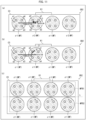
- FIG. 11 (a) is a front view of an optical device OD2 in accordance with a first variation.
- (b) is a front view of an optical device OD2 in accordance with a second variation.
- (c) is a front view of an optical device OD2 in accordance with a third variation.
- a multi-core fiber bundle MFB includes at least two multi-core fibers MF in which cores having the same core number at least partially overlap each other as a result of subjecting, to translation and inversion, end surfaces of the at least two multi-core fibers MF which end surfaces are closer to the first multi-core connector C3.
- (a) of Fig. 11 illustrates that this relation is satisfied by a multi-core fiber MF which is first from the left and a multi-core fiber MF which is second from the left.
- the core a1 and the core a2 are connected to each other (change between the core number 1 and the core number 2 occurs), and the core a3 and the core a4 are connected to each other (change between the core number 3 and the core number 4 occurs).
- the above configuration can make it easy to manage the core numbers in the multi-core fibers at the time of connection of two multi-core fibers MF for network construction.
- inversion can be inversion with respect to an axis which is in parallel with inclination directions of the multi-core fibers MF or inversion with respect to an axis perpendicular to the inclination directions of the multi-core fibers MF.
- translation can be translation along a direction which is in parallel with the inclination direction of the end surface of the first multi-core connector C3 or translation along a direction which is perpendicular to the inclination direction of the end surface of the first multi-core connector C3.
- the above-described at least two multi-core fibers MF are arranged in parallel with the inclination direction of the end surface of the first multi-core connector C3. Meanwhile, in the latter case, the above-described at least two multi-core fibers MF are arranged so as to be perpendicular to the inclination direction of the end surface of the first multi-core connector C3. In any of these cases, the above-described effect can be attained. Further, particularly in the latter case, distances between (i) a virtual axis which is perpendicular to the inclination direction of the end surface of the first multi-core connector C3 and (ii) centers of markers c in the above-described at least two multi-core fibers MF are equal to each other.
- all the multi-core fibers MF constituting the multi-core fiber bundle MFB preferably satisfy the above-described relation of translation and inversion. This makes it possible to cause change in the same core numbers in all the multi-core fibers MF constituting the multi-core fiber bundle MFB.
- the above-described translation is translation along a direction perpendicular to the inclination direction of the end surface of the first multi-core connector C3
- the above configuration makes it easy to simultaneously observe the markers c of all the multi-core fibers MF constituting the multi-core fiber bundle MFB.
- a multi-core fiber bundle MFB includes at least two multi-core fibers MF in which cores having the same core number at least partially overlap each other, as a result of subjecting, to translation and rotation, end surfaces of the at least two multi-core fibers MF which end surfaces are closer to the first multi-core connector C3.
- (b) of Fig. 11 illustrates that this relation is satisfied by a multi-core fiber MF which is first from the left and a multi-core fiber MF which is second from the left.
- the core a1 and the core a4 are connected to each other (change in the core number 1 and the core number 4 occurs), and the core a2 and the core a3 are connected to each other (change in the core number 2 and the core number 3 occurs).
- This can enhance a degree of freedom in wiring carried out to construct a network with use of the optical device OD2.
- rotation In a case where arrangement of cores a1 to an in a multi-core fiber MF has n-fold symmetry, assumed as the above-described rotation can be rotation of m ⁇ 360°/n (m is a natural number which is not less than 1 and not more than n-1). For example, in a case where arrangement of the cores a1 to a4 in the multi-core fiber MF has four-fold symmetry, 90° rotation, 180° rotation, and 270° rotation are assumed.
- the multi-core fiber bundle MFB is constituted by a first multi-core fiber group MFB1 and a second multi-core fiber group MFB2.
- the first multi-core connector MFB1 is a group of a plurality of (four in the example illustrated in (c) of Fig. 11 ) multi-core fibers MF whose end surfaces closer to the first multi-core connector C3 are aligned along an axis L on one side of the axis L.
- the second multi-core fiber group MFB2 is a group of a plurality of (four in the example illustrated in (c) of Fig.
- multi-core fibers MF whose end surfaces closer to the first multi-core connector C3 are aligned along the axis L on the other side of the axis L.
- the axis L is an axis orthogonal to an inclination direction of the end surfaces of the multi-core connectors MF which end surfaces are closer to the first multi-core connector C3.
- the multi-core fibers MF constituting the first multi-core fiber group MFB1 and the multi-core fibers MF constituting the second multi-core fiber group MFB2 have been subjected to rotation alignment such that distances from the markers c to the above axis L are shorter than distances from the cores a1 to an to the above axis L.
- the marker c is disposed near the above axis L.
- a focus of an objective lens is set on the above axis L. During this, thanks to the arrangement in which the marker c is disposed near the above axis L, it is easy to observe the marker c.
- the plurality of multi-core fibers MF constituting the multi-core fiber bundle MFB may be arranged in any manner.
- the multi-core fibers MF are arranged in matrix where a row direction is a direction which is in parallel with the inclination direction of the end surface of the first multi-core connector C3 and a column direction which is a direction perpendicular to the inclination direction of the end surface of the first multi-core connector C3, it is preferable that the number of rows be smaller than the number of columns. This is because that, in a case where the end surface of the first multi-core connector C3 is observed from the front with use of a microscope or the like, the above arrangement makes it even easier to observe the marker c in each multi-core fiber MF.
- FIG. 12 a multi-core fiber assembly MFS in accordance with a seventh embodiment of the present invention.
- (a) is a side view of the multi-core fiber assembly MFS and (b) is a perspective view of the multi-core fiber assembly MFS.
- the multi-core fiber assembly MFS includes a first multi-core fiber MF1 and a second multi-core fiber MF2.
- the first multi-core fiber MF1 and the second multi-core fiber MF2 may or may not be connected to each other.
- the later-described first end surface ⁇ 1 and the later-described second end surface ⁇ 2 are connected to each other (e.g., via connector connection or fusion splicing).
- the first multi-core fiber MF1 is configured similarly to the multi-core fiber MF shown in Fig. 1 .
- the first end surface ⁇ 1 essentially needs to be inclined but the second end surface ⁇ 2 does not essentially need to be inclined.
- an end surface of the first multi-core fiber MF1 which end surface essentially needs to be inclined that is, an end surface corresponding to the first end surface ⁇ 1 of the multi-core fiber MF shown in Fig. 1 will be called a "first end surface ⁇ 1".
- the second multi-core fiber MF2 is configured similarly to the multi-core fiber MF shown in Fig. 1 .
- the second end surface ⁇ 2 essentially needs to be inclined but the first end surface ⁇ 1 does not essentially need to be inclined.
- an end surface of the second multi-core fiber MF2 which end surface essentially needs to be inclined that is, an end surface corresponding to the second end surface ⁇ 2 of the multi-core fiber MF shown in Fig. 1 will be called a "second end surface ⁇ 2".
- An inclination direction v1 of the first end surface ⁇ 1 and an inclination direction v2 of the second end surface ⁇ 2 are defined so as to satisfy the following condition 1.
- Condition 1 In a case where the first end surface ⁇ 1 and the second end surface ⁇ 2 are brought into surface contact with each other so as to minimize an angle made by an extending direction of the cores a1 to an in the first end surface ⁇ 1 and an extending direction of the cores a1 to an in the second end surface ⁇ 2, each of the cores a1 to an in the first end surface ⁇ 1 at least partially overlaps any of the cores a1 to an in the second end surface ⁇ 2.
- the cores a1 to an in the first multi-core fiber MF1 and the cores a1 to an in the second multi-core fiber MF2 can be optically coupled to each other.
- the expression that the first end surface ⁇ 1 and the second end surface ⁇ 2 are connected to each other means that the first end surface ⁇ 1 and the second end surface ⁇ 2 are connected to each other "so as to minimize the angle made by the extending direction of the cores a1 to an in the first multi-core fiber MF1 and the extending direction of the cores a1 to an in the second multi-core fiber MF2".
- the inclination angle ⁇ 1 of the first end surface ⁇ 1 and the inclination angle ⁇ 2 of the second end surface ⁇ 2 may or may not be equal to each other.
- the inclination angle ⁇ 1 of the first end surface ⁇ 1 and the inclination angle ⁇ 2 of the second end surface ⁇ 2 are preferably equivalent to each other (substantially equal to each other), more preferably equal to each other (completely equal to each other).
- the expression that the inclination angle ⁇ 1 of the first end surface ⁇ 1 and the inclination angle ⁇ 2 of the second end surface ⁇ 2 are equivalent to each other (substantially equal to each other) means, for example, that a difference
- a minimum value of the angle made by the extending direction of the cores a1 to an in the first end surface ⁇ 1 and the extending direction of the cores a1 to an in the second end surface ⁇ 2 is 0°.
- Condition 1' In a case where the first end surface ⁇ 1 and the second end surface ⁇ 2 are brought into surface contact with each other so as to make the extending direction of the cores a1 to an in the first end surface ⁇ 1 and the extending direction of the cores a1 to an in the second end surface ⁇ 2 coincide with each other, each of the cores a1 to an in the first end surface ⁇ 1 at least partially overlaps any of the cores a1 to an in the second end surface ⁇ 2.
- the cores a1 to an in the first multi-core fiber MF1 and the cores a1 to an in the second multi-core fiber MF2 can be optically coupled to each other.
- the expression that the first end surface ⁇ 1 and the second end surface ⁇ 2 are connected to each other means that the first end surface ⁇ 1 and the second end surface ⁇ 2 are connected to each other "so as to make the extending direction of the cores a1 to an in the first multi-core fiber MF1 and the extending direction of the cores a1 to an in the second multi-core fiber MF2 coincide with each other".
- the inclination direction v1 of the first end surface ⁇ 1 of the first multi-core fiber MF1 and the inclination direction v2 of the second end surface ⁇ 2 of the second multi-core fiber MF2 are defined so as to satisfy, in addition to the above-described condition 1, the following condition 2.
- pairs of cores which at least partially overlap each other are (1) a pair of the core a1 in the first end surface ⁇ 1 and the core a1 in the second end surface ⁇ 2, (2) a pair of the core a2 in the first end surface ⁇ 1 and the core a2 in the second end surface ⁇ 2, (3) a pair of the core a3 in the first end surface ⁇ 1 and the core a3 in the second end surface ⁇ 2, and (4) a pair of the core a4 in the first end surface ⁇ 1 and the core a4 in the second end surface ⁇ 2. Also in any of the four pairs, two cores constituting the pair have the same core number.
- first end surface ⁇ 1 of the first multi-core fiber MF1 and the second end surface ⁇ 2 of the second multi-core fiber MF2 are connected to each other such that the first multi-core fiber MF1 and the second multi-core fiber MF2 are aligned in a single straight line as much as possible, cores having the same core number can be optically coupled to each other.
- first multi-core fiber MF1 which end is closer to the first end surface ⁇ 1 may be provided with a first single-core connector C1, as shown in (c) of Fig. 12 .
- second multi-core fiber MF2 which end is closer to the second end surface ⁇ 2 may be provided with a second single-core connector C2, as shown in (c) of Fig. 12 .
- Configurations and the like of the first single-core connector C1 and the second single-core connector C2 are as described with reference to Fig. 9 . Therefore, descriptions thereof are omitted here.
- the present embodiment employs, as the first multi-core fiber MF1, the multi-core fiber having the inclination direction v1 being from a center of the first end surface ⁇ 1 toward an intermediate point between the cores a4 and a1.
- the first multi-core fiber MF1 is not limited to this.
- Each of the following multi-core fibers can also be used as the first multi-core fiber MF1: (1) a multi-core fiber having an inclination direction v1 being from a center of a first end surface ⁇ 1 toward an intermediate point between cores a1 and a2; (2) a multi-core fiber having an inclination direction v1 being from a center of a first end surface ⁇ 1 toward an intermediate point between cores a2 and a3; and (3) a multi-core fiber having an inclination direction v1 being from a center of a first end surface ⁇ 1 toward an intermediate point between cores a3 and a4.
- each of the following multi-core fibers can also be used as the first multi-core fiber MF1: (1) a multi-core fiber having an inclination direction v1 being from a center of a first end surface ⁇ 1 toward a core a1; (2) a multi-core fiber having an inclination direction v1 being from a center of a first end surface ⁇ 1 toward a core a2; (3) a multi-core fiber having an inclination direction v1 being from a center of a first end surface ⁇ 1 toward a core a3; and (4) a multi-core fiber having an inclination direction v1 being from a center of a first end surface ⁇ 1 toward a core a4.
- This also applies to the second multi-core fiber MF2.
- FIG. 13 a multi-core fiber assembly MFS in accordance with a seventh embodiment of the present invention.
- (a) is a side view of the multi-core fiber assembly MFS and (b) is a perspective view of the multi-core fiber assembly MFS.
- the multi-core fiber assembly MFS includes a first multi-core fiber MF1 and a second multi-core fiber MF2.
- the first multi-core fiber MF1 and the second multi-core fiber MF2 may or may not be connected to each other.
- the later-described first end surface ⁇ 1 and the later-described second end surface ⁇ 2 are connected to each other (e.g., via fusion splicing).
- the first multi-core fiber MF1 is configured similarly to the multi-core fiber MF shown in Fig. 1 .
- the first end surface ⁇ 1 essentially needs to be inclined but the second end surface ⁇ 2 does not essentially needs to be inclined.
- An end surface of the first multi-core fiber MF1 which end surface essentially needs to be inclined, that is, an end surface corresponding to the first end surface ⁇ 1 of the multi-core fiber MF shown in Fig. 1 will be called a "first end surface ⁇ 1".
- the second multi-core fiber MF2 is configured similarly to the multi-core fiber MF shown in Fig. 1 .
- the first end surface ⁇ 1 essentially needs to be inclined but the second end surface ⁇ 2 does not essentially need to be inclined.
- An end surface of the second multi-core fiber MF2 which end surface essentially needs to be inclined, that is, an end surface corresponding to the first end surface ⁇ 1 of the multi-core fiber MF shown in Fig. 1 will be called a "second end surface ⁇ 2".
- the inclination direction v1 of the first end surface ⁇ 1 and the inclination direction v2 of the second end surface ⁇ 2 are defined so as to satisfy, in addition to the above-described condition 1, the above-described condition 2.
- the inclination direction v1 of the first end surface ⁇ 1 and the inclination direction v2 of the second end surface ⁇ 2 are defined so as to satisfy, in addition to the above-described condition 1, the following condition 3.
- Condition 3 In a case where the first end surface ⁇ 1 and the second end surface ⁇ 2 are brought into surface contact with each other so as to minimize an angle made by an extending direction of cores a1 to an in the first end surface ⁇ 1 and an extending direction of cores a1 to an in the second end surface ⁇ 2, cores which at least partially overlap each other have different core numbers.
- pairs of cores which at least partially overlap each other are (1) a pair of the core a1 in the first end surface ⁇ 1 and the core a2 in the second end surface ⁇ 2, (2) a pair of the core a2 in the first end surface ⁇ 1 and the core a1 in the second end surface ⁇ 2, (3) a pair of the core a3 in the first end surface ⁇ 1 and the core a4 in the second end surface ⁇ 2, and (4) a pair of the core a4 in the first end surface ⁇ 1 and the core a3 in the second end surface ⁇ 2. Also in any of the four pairs, two cores constituting the pair have different core numbers.
- first end surface ⁇ 1 of the first multi-core fiber MF1 and the second end surface ⁇ 2 of the second multi-core fiber MF2 are connected to each other such that the first multi-core fiber MF1 and the second multi-core fiber MF2 are aligned in a single straight line as much as possible, cores having different core numbers can be optically coupled to each other.
- first multi-core fiber MF1 which end is closer to the first end surface ⁇ 1 may be provided with a first single-core connector C1, as shown in (c) of Fig. 13 .
- second multi-core fiber MF2 which end is closer to the second end surface ⁇ 2 may be provided with a second single-core connector C2, as shown in (c) of Fig. 13 .
- Configurations and the like of the first single-core connector C1 and the second single-core connector C2 are as described with reference to Fig. 9 . Therefore, descriptions thereof are omitted here.
- the present embodiment employs, as the first multi-core fiber MF1, the multi-core fiber having the inclination direction v1 being from a center of the first end surface ⁇ 1 toward an intermediate point between the cores a4 and a1.
- the first multi-core fiber MF1 is not limited to this.
- Each of the following multi-core fibers can also be used as the first multi-core fiber MF1: (1) a multi-core fiber having an inclination direction v1 being from a center of a first end surface ⁇ 1 toward an intermediate point between cores a1 and a2; (2) a multi-core fiber having an inclination direction v1 being from a center of a first end surface ⁇ 1 toward an intermediate point between cores a2 and a3; and (3) a multi-core fiber having an inclination direction v1 being from a center of a first end surface ⁇ 1 toward an intermediate point between cores a3 and a4.
- each of the following multi-core fibers can also be used as the first multi-core fiber MF1: (1) a multi-core fiber having an inclination direction v1 being from a center of a first end surface ⁇ 1 toward a core a1; (2) a multi-core fiber having an inclination direction v1 being from a center of a first end surface ⁇ 1 toward a core a2; (3) a multi-core fiber having an inclination direction v1 being from a center of a first end surface ⁇ 1 toward a core a3; and (4) a multi-core fiber having an inclination direction v1 being from a center of a first end surface ⁇ 1 toward a core a4.
- This also applies to the second multi-core fiber MF2.
- a multi-core fiber in accordance with a first aspect of the present invention employs a configuration of a multi-core fiber including: a cladding; a plurality of cores formed inside the cladding; and a first end surface and a second end surface each of which is inclined so as not to be orthogonal to an extending direction of the plurality of cores, inclination directions of the first end surface and the second end surface being set so that, in a case where the first end surface and the second end surface are brought into surface contact with each other so as to minimize an angle made by an extending direction of the plurality of cores in the first end surface and an extending direction of the plurality of cores in the second end surface, each of the plurality of cores in the first end surface at least partially overlaps any of the plurality of cores in the second end surface.
- a multi-core fiber in accordance with a second aspect of the present invention employs, in addition to the configuration of the first aspect, a configuration wherein: an inclination angle of the first end surface and an inclination angle of the second end surface are equivalent to each other.
- a multi-core fiber in accordance with a third aspect of the present invention employs, in addition to the configuration of the first or second aspect, a configuration wherein: in the first end surface and the second end surface, core numbers of the plurality of cores are identifiable; and in a case where the first end surface and the second end surface are brought into surface contact with each other so as to minimize the angle, cores which at least partially overlap each other have a same core number.
- a multi-core fiber in accordance with a fourth aspect of the present invention employs, in addition to the configuration of the first or second aspect, a configuration wherein: in the first end surface and the second end surface, core numbers of the plurality of cores are identifiable; and in a case where the first end surface and the second end surface are brought into surface contact with each other so as to minimize the angle, cores which at least partially overlap each other have different core numbers.
- a multi-core fiber in accordance with a fifth aspect of the present invention employs, in addition to the configuration of any one of the first to fourth aspects, a configuration wherein: in each of the first end surface and the second end surface, the plurality of cores are arranged in a linearly symmetric manner with respect to a virtual axis which is orthogonal to the inclination direction and which passes through a center of the cladding.
- a multi-core fiber in accordance with a sixth aspect of the present invention employs, in addition to the configuration of the fifth aspect, a configuration wherein: in the first end surface and the second end surface, the virtual axis does not cross any of the plurality of cores.
- a multi-core fiber in accordance with a seventh aspect of the present invention employs, in addition to the configuration of the fifth or sixth aspect, a configuration wherein: the multi-core fiber further include a marker formed in the cladding, wherein in each of the first end surface and the second end surface, a center of the marker is disposed between (i) the virtual axis and (ii) a straight line which passes through a center of, among the plurality of cores, a core farthest from the virtual axis and which is in parallel with the virtual axis.
- An optical device in accordance with an eighth aspect of the present invention employs a configuration wherein the optical device includes: a multi-core fiber; and a single-core connector provided to one end of the multi-core fiber, the multi-core fiber being a multi-core fiber in accordance with any one of the first to seventh aspects.
- An optical device in accordance with a ninth aspect of the present invention employs a configuration wherein the optical device includes: a multi-core fiber bundle which is a bundle of a plurality of multi-core fibers; and a multi-core connector or an integrated single-core connector group, the multi-core connector or the single-core connector group being provided to one end of the multi-core fiber bundle, each of the plurality of multi-core fibers being a multi-core fiber in accordance with any one of the first to seventh aspects, the plurality of multi-core fibers being fixed to the multi-core connector or the single-core connector group such that connector-side end surfaces of the plurality of multi-core fibers are all inclined in a specific inclination direction, each of the connector-side end surfaces being one of the first end surface and the second end surface, the one of the first end surface and the second end surface being provided with the multi-core connector or the single-core connector group.
- An optical device in accordance with a tenth aspect of the present invention employs, in addition to the configuration in accordance with the ninth aspect, a configuration wherein: each of the plurality of multi-core fibers is configured such that core numbers of the plurality of cores are identifiable in the connector-side end surface; and the plurality of multi-core fibers include multi-core fibers in which cores having a same core number at least partially overlap each other as a result of subjecting the connector-side end surfaces of the multi-core fibers to translation and inversion.
- An optical device in accordance with an eleventh aspect of the present invention employs, in addition to the configuration in accordance with the tenth aspect, a configuration wherein: the inversion is inversion carried out with respect to a virtual axis which is in parallel with the inclination direction or inversion with respect to a virtual axis which is orthogonal to the inclination direction.
- An optical device in accordance with an twelfth aspect of the present invention employs, in addition to the configuration in accordance with the ninth aspect, a configuration wherein: each of the plurality of multi-core fibers is configured such that core numbers of the plurality of cores are identifiable in the connector-side end surface; and the plurality of multi-core fibers include multi-core fibers in which cores having a same core number at least partially overlap each other as a result of subjecting the connector-side end surfaces of the multi-core fibers to translation and rotation.
- An optical device in accordance with a thirteenth aspect of the present invention employs, in addition to the configuration in accordance with any one of the tenth to twelfth aspects, a configuration wherein: each of the plurality of multi-core fibers includes a marker formed inside the cladding; the plurality of multi-core fibers are constituted by a first multi-core fiber group and a second multi-core fiber group, the first multi-core fiber group including multi-core fibers whose connector-side end surfaces are aligned along a virtual axis orthogonal to the specific direction and are arranged on one side of the virtual axis, the second multi-core fiber group including multi-core fibers whose connector-side end surfaces are aligned along the virtual axis and are arranged on the other side of the virtual axis; and in each of the connector-side end surfaces of the plurality of multi-core fibers, a distance from the marker to the virtual axis is shorter than distances from the plurality of cores to the virtual axis.
- An optical device in accordance with a fourteenth aspect of the present invention employs a configuration wherein the optical device further includes: a Fan-In/Fan-Out device including an optical path conversion section and a multi-core fiber, the multi-core fiber being a multi-core fiber in accordance with in any one of the eighth to thirteenth aspects or the multi-core fiber being connected to a multi-core fiber in accordance with in any one of the eighth to thirteenth aspects.
- a Fan-In/Fan-Out device including an optical path conversion section and a multi-core fiber, the multi-core fiber being a multi-core fiber in accordance with in any one of the eighth to thirteenth aspects or the multi-core fiber being connected to a multi-core fiber in accordance with in any one of the eighth to thirteenth aspects.
- a multi-core fiber in accordance with a fifteenth aspect of the present invention employs a configuration of a multi-core fiber assembly including at least one first multi-core fiber and at least one second multi-core fiber, the at least one first multi-core fiber including a cladding, a plurality of cores formed inside the cladding, and a first end surface inclined so as not to be orthogonal to an extending direction of the plurality of cores, the at least one second multi-core fiber including a cladding, a plurality of cores formed inside the cladding, and a second end surface inclined so as not to be orthogonal to an extending direction of the plurality of cores, inclination directions of the first end surface and the second end surface being set so that, in a case where the first end surface and the second end surface are brought into surface contact with each other so as to minimize an angle made by the extending direction of the plurality of cores in the first end surface and the extending direction of the plurality of cores in the second end surface, each of the plurality
- the present invention is not limited to the embodiments, but can be altered by a skilled person in the art within the scope of the claims.
- the present invention also encompasses, in its technical scope, any embodiment derived by combining technical means disclosed in differing embodiments.
- the multi-core fiber may be twisted.
- a multi-core fiber satisfying the condition(s) recited in the claims is encompassed in the technical scope of the present invention, independently of whether or not the multi-core fiber is twisted.
- the connector may have any shape.
- the technical scope of the present invention also encompasses (i) an optical device including a connector of a type that has a fiber hole to which a multi-core fiber can be inserted and fixed or (ii) an optical device including a connector of a type that as a V-groove in which a multi-core fiber can be housed and fixed.
- the end surface of the multi-core fiber may be (i) a flat surface, (ii) a curved surface (e.g., a concaved spherical surface or a recessed spherical surface) which can be approximated by a flat surface, or (iii) a curved surface which can be approximated on the basis of data of a virtual end surface obtained by subtracting, from data of an end surface of a case where surface roughness is present, data of a virtual end surface of a case where the end surface is fitted.
- a curved surface e.g., a concaved spherical surface or a recessed spherical surface
- the above-described virtual axis can be defined as below, for example. That is, in the end surface of the multi-core fiber or the end surface of the multi-core fiber included in the optical device, a virtual axis extending in a direction orthogonal to a direction of, among an X-axis direction component and a Y-axis direction component into which vector components of the above-described inclination direction are divided, the one having a larger scalar quantity can be defined as the virtual axis.
- a virtual axis that can be determined on the basis of the defining structure can be defined as the virtual axis.
- the above-described defining structure encompass two guide holes, two guide pins, one guide hole, and one guide pin each provided to an end surface of the optical device.
- a virtual axis orthogonal to the virtual axis can be defined as the virtual axis.
- examples of the above-described defining structure include two multi-core fibers exposed from the end surface of the optical device.
- a virtual axis passing through centers of the two multi-core fibers or a virtual axis orthogonal to the virtual axis can be expressed as the virtual axis.
- examples of the above-described defining structure include a ferrule, a flange, an array, a housing, and the like each of which has profile of a polygonal shape, a recessed shape, a projected shape, or an anisotropic shape (e.g., a barrel shape or a shape with a cutout) provided to an optical device.
- a virtual axis extending in a specific direction which can be determined on the basis of the above profile or
- a virtual axis orthogonal to the virtual axis can be defined as the virtual axis.
Landscapes
- Physics & Mathematics (AREA)
- General Physics & Mathematics (AREA)
- Optics & Photonics (AREA)
- Engineering & Computer Science (AREA)
- Plasma & Fusion (AREA)
- Optical Couplings Of Light Guides (AREA)
- Mechanical Coupling Of Light Guides (AREA)
- Optical Fibers, Optical Fiber Cores, And Optical Fiber Bundles (AREA)
Applications Claiming Priority (2)
| Application Number | Priority Date | Filing Date | Title |
|---|---|---|---|
| JP2022126586 | 2022-08-08 | ||
| PCT/JP2023/020031 WO2024034234A1 (ja) | 2022-08-08 | 2023-05-30 | マルチコアファイバ、光デバイス、及びマルチコアファイバ集合体 |
Publications (1)
| Publication Number | Publication Date |
|---|---|
| EP4571375A1 true EP4571375A1 (en) | 2025-06-18 |
Family
ID=89851313
Family Applications (1)
| Application Number | Title | Priority Date | Filing Date |
|---|---|---|---|
| EP23852218.9A Pending EP4571375A1 (en) | 2022-08-08 | 2023-05-30 | Multicore fiber, optical device, and multicore fiber assembly |
Country Status (5)
| Country | Link |
|---|---|
| US (1) | US20250383502A1 (https=) |
| EP (1) | EP4571375A1 (https=) |
| JP (2) | JP7594129B2 (https=) |
| CN (1) | CN119422088A (https=) |
| WO (1) | WO2024034234A1 (https=) |
Cited By (1)
| Publication number | Priority date | Publication date | Assignee | Title |
|---|---|---|---|---|
| US20240231006A9 (en) * | 2022-10-24 | 2024-07-11 | Sumitomo Electric Industries, Ltd. | Optical fiber bundle and optical switch |
Families Citing this family (1)
| Publication number | Priority date | Publication date | Assignee | Title |
|---|---|---|---|---|
| JP7591600B2 (ja) * | 2023-03-31 | 2024-11-28 | 株式会社フジクラ | マルチコアファイバ、光デバイス、ファンイン/ファンアウトデバイス、及びマルチコアファイバ集合体 |
Family Cites Families (8)
| Publication number | Priority date | Publication date | Assignee | Title |
|---|---|---|---|---|
| US6520689B2 (en) * | 2001-07-17 | 2003-02-18 | Corning Incorporated | Optical fiber splicing method and device |
| JP2013117664A (ja) * | 2011-12-05 | 2013-06-13 | Sumitomo Electric Ind Ltd | マルチコア光ファイバ接続構造体およびマルチコア光ファイバ接続構造体製造方法 |
| JP2014197094A (ja) * | 2013-03-29 | 2014-10-16 | 住友電気工業株式会社 | マルチコア光ファイバ |
| WO2017130627A1 (ja) * | 2016-01-25 | 2017-08-03 | 日本電信電話株式会社 | 調心装置、及び、調心方法 |
| JP7368089B2 (ja) | 2018-03-02 | 2023-10-24 | 株式会社フジクラ | マルチコアファイバ、光コネクタ、ファンイン/ファンアウトデバイス |
| JP2022039849A (ja) * | 2020-08-28 | 2022-03-10 | 株式会社 オプトクエスト | マルチコアファイバ結合系 |
| CN116057438A (zh) * | 2020-12-04 | 2023-05-02 | 株式会社藤仓 | 光纤连接体、光通信系统、光设备、以及光纤连接体的制造方法 |
| CN113075763B (zh) * | 2021-03-11 | 2022-07-15 | 武汉长盈通光电技术股份有限公司 | 多芯熊猫结构保偏光纤及其耦合连接装置 |
-
2023
- 2023-05-30 US US18/875,985 patent/US20250383502A1/en active Pending
- 2023-05-30 CN CN202380047702.2A patent/CN119422088A/zh active Pending
- 2023-05-30 JP JP2023553076A patent/JP7594129B2/ja active Active
- 2023-05-30 EP EP23852218.9A patent/EP4571375A1/en active Pending
- 2023-05-30 WO PCT/JP2023/020031 patent/WO2024034234A1/ja not_active Ceased
-
2024
- 2024-11-21 JP JP2024203220A patent/JP2025020464A/ja active Pending
Cited By (2)
| Publication number | Priority date | Publication date | Assignee | Title |
|---|---|---|---|---|
| US20240231006A9 (en) * | 2022-10-24 | 2024-07-11 | Sumitomo Electric Industries, Ltd. | Optical fiber bundle and optical switch |
| US12523823B2 (en) * | 2022-10-24 | 2026-01-13 | Sumitomo Electric Industries, Ltd. | Optical fiber bundle and optical switch |
Also Published As
| Publication number | Publication date |
|---|---|
| US20250383502A1 (en) | 2025-12-18 |
| JP2025020464A (ja) | 2025-02-12 |
| WO2024034234A1 (ja) | 2024-02-15 |
| JPWO2024034234A1 (https=) | 2024-02-15 |
| CN119422088A (zh) | 2025-02-11 |
| JP7594129B2 (ja) | 2024-12-03 |
Similar Documents
| Publication | Publication Date | Title |
|---|---|---|
| EP4258028A1 (en) | Fiber connecting body, optical communication system, optical device, and method for manufacturing fiber connecting body | |
| EP2998770B1 (en) | Optical connector and manufacturing method for optical connector | |
| EP4571374A1 (en) | Multicore fiber, optical device, and method for manufacturing multicore fiber | |
| US11215767B2 (en) | Fiber optic adapter and cassette | |
| US8297854B2 (en) | Multimode fiber optic assemblies | |
| EP4571375A1 (en) | Multicore fiber, optical device, and multicore fiber assembly | |
| EP2998771B1 (en) | Ferrule | |
| CN111221083B (zh) | 一种多芯光纤单芯连接器及其制备和对准方法 | |
| EP3734338B1 (en) | Connection device, optical connector manufacturing device, connection method, and method for manufacturing optical connector | |
| US10775569B2 (en) | Optical connector and optical connection structure | |
| US20110249943A1 (en) | Gender-neutral mpo connectors | |
| US20210389528A1 (en) | Optical connector ferrule, sleeve, and method for manufacturing ferrule member | |
| US20140233893A1 (en) | Backwards compatible multi-core fiber optic cable | |
| JPWO2024034234A5 (https=) | ||
| US12613379B2 (en) | Splice-on optical connectors for multicore fibers | |
| JP7591600B2 (ja) | マルチコアファイバ、光デバイス、ファンイン/ファンアウトデバイス、及びマルチコアファイバ集合体 | |
| EP4632454A1 (en) | Connector-equipped optical fiber cable and optical transmission system | |
| WO2025179509A1 (en) | Multicore fiber with fan-in fan-out design | |
| US12339501B2 (en) | Optical connection component and connector assembly | |
| EP4538761A1 (en) | Control device, fusion connection device, connector connection device, and control program | |
| US20250271619A1 (en) | Multicore fiber fan-in fan-out design | |
| Bickham et al. | Sharon Lutz1, Scott Mendenhall1, Tom Mitcheltree1, Lucas Schmidt1, Dirk Schoellner1 |
Legal Events
| Date | Code | Title | Description |
|---|---|---|---|
| STAA | Information on the status of an ep patent application or granted ep patent |
Free format text: STATUS: THE INTERNATIONAL PUBLICATION HAS BEEN MADE |
|
| PUAI | Public reference made under article 153(3) epc to a published international application that has entered the european phase |
Free format text: ORIGINAL CODE: 0009012 |
|
| STAA | Information on the status of an ep patent application or granted ep patent |
Free format text: STATUS: REQUEST FOR EXAMINATION WAS MADE |
|
| 17P | Request for examination filed |
Effective date: 20241211 |
|
| AK | Designated contracting states |
Kind code of ref document: A1 Designated state(s): AL AT BE BG CH CY CZ DE DK EE ES FI FR GB GR HR HU IE IS IT LI LT LU LV MC ME MK MT NL NO PL PT RO RS SE SI SK SM TR |
|
| DAV | Request for validation of the european patent (deleted) | ||
| DAX | Request for extension of the european patent (deleted) |