EP4571007A1 - Universaler regenwasserablauf für den rand einer dachstruktur und geneigtes dach mit einer dachstruktur mit einem solchen rand - Google Patents
Universaler regenwasserablauf für den rand einer dachstruktur und geneigtes dach mit einer dachstruktur mit einem solchen rand Download PDFInfo
- Publication number
- EP4571007A1 EP4571007A1 EP24000142.0A EP24000142A EP4571007A1 EP 4571007 A1 EP4571007 A1 EP 4571007A1 EP 24000142 A EP24000142 A EP 24000142A EP 4571007 A1 EP4571007 A1 EP 4571007A1
- Authority
- EP
- European Patent Office
- Prior art keywords
- roof
- gutter
- plates
- longitudinal
- ribs
- Prior art date
- Legal status (The legal status is an assumption and is not a legal conclusion. Google has not performed a legal analysis and makes no representation as to the accuracy of the status listed.)
- Pending
Links
Images




Classifications
-
- E—FIXED CONSTRUCTIONS
- E04—BUILDING
- E04D—ROOF COVERINGS; SKY-LIGHTS; GUTTERS; ROOF-WORKING TOOLS
- E04D13/00—Special arrangements or devices in connection with roof coverings; Protection against birds; Roof drainage ; Sky-lights
- E04D13/14—Junctions of roof sheathings to chimneys or other parts extending above the roof
- E04D13/147—Junctions of roof sheathings to chimneys or other parts extending above the roof specially adapted for inclined roofs
- E04D13/1473—Junctions of roof sheathings to chimneys or other parts extending above the roof specially adapted for inclined roofs specially adapted to the cross-section of the parts extending above the roof
- E04D13/1475—Junctions of roof sheathings to chimneys or other parts extending above the roof specially adapted for inclined roofs specially adapted to the cross-section of the parts extending above the roof wherein the parts extending above the roof have a generally rectangular cross-section
-
- E—FIXED CONSTRUCTIONS
- E04—BUILDING
- E04D—ROOF COVERINGS; SKY-LIGHTS; GUTTERS; ROOF-WORKING TOOLS
- E04D13/00—Special arrangements or devices in connection with roof coverings; Protection against birds; Roof drainage ; Sky-lights
- E04D13/02—Roof-covering aspects of dormer windows
Definitions
- the invention relates to the roofs of buildings.
- It relates more particularly to a universal gutter for the flow of rainwater at the periphery of a roof structure, integrated into a sloping section of a roof.
- roof structures include skylights and dormer windows.
- a rectangular frame is inserted into the roof slope and contains a tilting opening, incorporating glazing.
- two side cheeks of the dormer are fixed to the roof frame.
- the two cheeks are connected by the window frame and the assembly of cheeks and frame is topped with a waterproof covering connected to the roof.
- the invention aims to remedy the aforementioned disadvantages of sloping roofs, incorporating roof windows, dormers, dormers or similar structures such as canopies or chimneys for example.
- the invention has the particular objective of providing a gutter for equipping roof windows, skylights or similar structures, which is of simple design and whose construction is easy and inexpensive.
- the invention is specifically aimed at providing a gutter which is universal, in the sense that it can be adapted easily to the majority of roof covering elements.
- the invention also relates to a newly designed sloping roof incorporating a roof window, dormer window, dormer or similar structure.
- the invention relates to a universal gutter for the flow of rainwater at the periphery of a roof structure, integrated into a sloping section of a roof, said gutter comprising a pair of longitudinal plates, an upper transverse plate and a lower transverse plate, said longitudinal plates and the upper transverse plate being designed to be inserted under covering elements of the roof section and the lower transverse plate being designed to overhang covering elements of the roof section;
- the gutter is characterized in that the longitudinal plates comprise, on the upper face, a succession of longitudinal grooves which extend over the entire length of the plates and in which longitudinal ribs are inserted.
- the invention applies to roofs which comprise a sloping slope and which incorporate a roof structure into said sloping slope.
- roof structure generally designates any type of roof window, skylight, fanlight, dormer window, dormer window or any other construction element which it It is common to incorporate into a sloping roof slope, for example, a chimney, a turret or a dovecote (list is exemplary, not exhaustive).
- the connection of the roof structure with the roof slope can have straight edges or curved edges. Straight edges are preferred. Polyhedral connections are preferred. Among these, parallelepiped connections are preferred, for example square, rectangular and trapezoidal connections.
- the gutter according to the invention is intended to be arranged around the roof structure, so as to channel rainwater around it and down the sloping slope of the roof, preventing water infiltration under the roof.
- it comprises a pair of longitudinal plates, an upper transverse plate and a lower transverse plate.
- longitudinal means the direction of the slope of the sloping roof face and "transverse” means a direction transverse to said longitudinal direction.
- longitudinal plates and transverse plates are defined by the position they occupy when the gutter is normally arranged around the roof structure, in the sloping roof face. The longitudinal plates are then directed in the direction of the slope of the sloping roof face and the transverse plates are directed transverse to the slope. The length of the longitudinal plates is then their dimension in the direction of the roof slope.
- the upper transverse plate is, by definition, at a higher level than the lower transverse plate.
- the gutter's longitudinal plates and the upper transverse plate are designed to fit under the roofing elements of the roof slope. They are normally placed on the roof frame, between it and the roofing elements, and are in direct contact with the roofing elements.
- the lower transverse plate is designed to overhang a row of roofing elements.
- the roofing elements may be any roofing elements commonly used in the building industry, such as rows of natural or synthetic tiles or slates, a rigid metal plate (e.g. lead or zinc), a rigid corrugated sheet (e.g. rigid polyvinyl chloride, metal or cement reinforced with a fibrous material) or a flexible waterproof sheet (e.g. a synthetic polymer sheet, a bitumen sheet or a flexible metal sheet) (example, non-limiting list).
- a rigid metal plate e.g. lead or zinc
- a rigid corrugated sheet e.g. rigid polyvinyl chloride, metal or cement reinforced with a fibrous material
- a flexible waterproof sheet e.g. a synthetic polymer sheet, a bitumen sheet or a flexible metal sheet
- the longitudinal plates and the transverse plates of the gutter according to the invention may be flat or corrugated. It is preferred that the plates are flat.
- the longitudinal plates and the transverse plates are normally made of a waterproof material, capable of withstanding the usual atmospheric conditions, during normal use of the gutter on the roof of a building.
- they can for example be made of metal (for example lead, zinc, galvanized steel, copper) or a synthetic polymer and be obtained by rolling, molding or extrusion (list exemplary, non-limiting).
- Synthetic polymers are preferred.
- the choice of polymer is not critical for the definition of the invention. It can be a rigid, semi-rigid or flexible polymer. It is advantageously an elastomer, possibly reinforced. Natural or synthetic mineral materials are well suited as reinforcing material for the elastomer, especially fibrous fillers (for example glass fibers and rock wool, mineral aggregates and metal wires and powders.
- the longitudinal plates comprise, on their upper face, a succession of longitudinal grooves, which extend over the entire length of the plates and longitudinal ribs are inserted into the grooves.
- the upper face of the plates is the one that is directed upwards, when the gutter is normally arranged around the roof structure, in the sloping roof slope.
- the lower face is the face that is normally directed downwards.
- the ribs are retained laterally in the grooves. They are generally fitted into the grooves and then have, in the area of their insertion into a groove, a profile complementary to that of the groove. This may be a square, rectangular or semi-circular profile (example list, not exhaustive). A trapezoidal dovetail profile is preferred.
- the ribs are preferably removable.
- the ribs normally extend along the entire length of the longitudinal plates and their function is to retain water laterally on the plate, preventing it from passing into the attic under the roof. They can be made of the same material as the longitudinal plates or of a different material. They are preferably rigid, semi-rigid or flexible.
- rib height depends on the roof covering elements, so that they fit under them.
- the ideal ribs are those whose height is approximately equal to the amplitude of these corrugated roofing elements.
- the height of the ribs is adjustable, so as to be able to adapt them to the different models of roof covering elements, commercially available, such as the interlocking tile, the canal tile, the Roman tile, the purlin tile or the Flemish tile (https://toiture.pro/types-formes-tuiles.php) (exemplary, non-exhaustive list).
- the ribs can be provided with marks defining predefined heights, each height corresponding to a defined model of roof covering element. It is then sufficient to cut the ribs at the height corresponding to the selected covering elements, for example by means of cutting pliers.
- the aforementioned marks advantageously comprise rib breaking zones.
- breaking zones can, for example, comprise longitudinal incisions, made in the ribs, allowing them to be broken precisely, by example by folding.
- the ribs are flexible slats whose height can be adapted by compression under the weight of the roof covering elements.
- the longitudinal plates of the gutter comprise a succession of grooves on each of their two faces.
- this is not essential, it is advantageous for the grooves on the upper face of the plates to alternate with the grooves on the lower face of the plates. This alternating arrangement of the grooves makes it possible to reduce the thickness of the plates and gives them optimum flexibility, allowing, in particular, to bend them at right angles, without difficulty and without risk of breaking them.
- the upper transverse plate is designed to be inserted under a transverse row of roof covering elements.
- the lower transverse plate is intended to form a cantilever above a row cross-section of roof covering elements.
- the gutter according to the invention is intended to serve as a watertight connection around a roof structure attached to an inclined roof plane. For this purpose, it is normally inserted between the roof covering elements and the framing slats, used to support these roof covering elements. It is specially designed for dormers, the term dormer designating, by definition, a window made in the roof of a building to provide daylight to the space under the roof (The new Petit Robert, Edition Dictionnaires Le Robert - Paris, June 2000, page 1469 ).
- dormer window refers indifferently to a dormer window, a bull's eye window or a skylight type roof window (such as those marketed under the VELUX ® brand and comprising glazing in the plane of a roof section) (example, non-limiting list).
- the longitudinal grooves of the longitudinal plates give them good flexibility. This flexibility facilitates their insertion into a corresponding groove in the roof structure.
- This groove in the roof structure may advantageously include a ventilation space provided between a load-bearing wall of the roof structure and cladding for the protection of this wall against the weather.
- the wall and its cladding may be the cheeks of the dormer window.
- the invention also relates to a roof comprising an inclined section, into which a structure is inserted. roof, the waterproofing of the roof at the periphery of said roof structure being achieved by means of a gutter according to the invention.
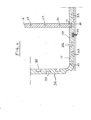
- FIG. 1 schematically shows an inclined section 44 of a roof, in longitudinal section (section in a vertical plane, parallel to the slope of the roof).
- An opening 45 is made in the roof section and this opening is covered by a dormer designated as a whole by the reference notation 46.
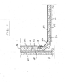
- the dormer 46 is shown in detail in figures 2 And 3 . It comprises two triangular side cheeks 2 and 3 (only cheek 2 is visible at figures 1 And 2 ) fixed to two rafters 47 of the roof frame 44 and supporting an awning 4.
- the two cheeks 2 and 3 and the awning 4 are connected by a frame 7-7' of the dormer window 46.
- the cheeks 2 and 3 comprise, for example, panels 48 made of wood or polymeric material, covered with a layer 49 of thermal insulation on their inner face.
- the thermal insulation layer 49 is covered with a finishing layer (not shown), which is both decorative and protective.
- the panels 48 are protected from the weather by cladding 50 made of a suitable material, for example a metal plate, a rigid polymeric material plate or a cement plate reinforced with a fibrous material of the Eternit ® (Etex) brand.
- Spacers 51 are interposed between the panels 48 and the cladding 50, so as to ensure ventilation.
- the 7-7' sleeper is a frame rectangular wooden beam, which rests on the roof frame by its lower transverse side 7' ( Figure 1 ).
- a wooden opening 8, carrying a glazing, is hinged in the frame 7-7'.
- the seal between the dog-seat 46 and the roof covering elements 44 is obtained by means of a gutter 9 arranged at the periphery of the dog-seat 46.
- the gutter 9 serves to collect rainwater around the dog-seat and to evacuate it towards the bottom of the roof.
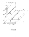
- the gutter 9 comprises a pair of longitudinal plates 10, along the cheeks 2 and 3 ( Figure 3 ), and a pair of transverse plates 26 and 40 ( Figure 2 ).
- the longitudinal plates 10 are placed on the purlin slats 52, along the cheeks 2 and 3 of the dog-seat 46 and they are partially covered by roof covering elements. They comprise a vertical longitudinal lip 36 which is engaged in a groove 55 between the panel 48 and the cladding 50, to achieve the sealing of the assembly.
- the upper transverse plate 40 of the gutter 9 is placed on the purlin slats, under the roof covering elements. It has a lip 42 ( Figure 2 ), which is engaged behind a corresponding lip 41 of the rear transverse end of the dog-seat.
- the lower transverse plate 26 of the gutter 9 is placed on the purlin slats and comprises a lip (not visible in the figures) which is engaged behind a corresponding lip (not visible in the figures) on the lower side 7' of the frame. Its lower end 34 overlaps a row of roof covering elements.
- the longitudinal plates 10 are substantially flat and carry three longitudinal ribs 11, 12 and 13.
- the plates 10 are advantageously obtained by molding or extrusion of a synthetic polymer. It is preferred that the plates 10 are made of flexible or semi-rigid synthetic polymer.
- the ribs 11, 12 and 13 are attached to the plates 10, as will be explained later. They are obtained by molding or extruding a flexible or semi-rigid synthetic polymer. The function of the ribs 11, 12, 13 will be explained later.
- FIG. 4 shows, on a larger scale, a particular embodiment of the longitudinal plates 10 of the gutter.
- These plates 10 comprise, on their upper face 37, a succession of grooves 32 and, on their lower face 38, a succession of grooves 33 (the expressions upper face and lower face being defined when the plate 10 is positioned on the roof slope).
- the grooves 32 and 33 extend over the entire length of the plate (the length being defined in the direction of the slope of the roof).
- the grooves 32 of the upper face of the plate 10 alternate with the grooves 33 of the lower face. This alternating arrangement of the grooves 32 and 33 makes it possible to reduce the thickness of the plate 10.
- the presence of the grooves 32 and 33 gives the plate 10 great flexibility, allowing it to be bent without difficulty, to form the vertical lip 36 defined above, with reference to the Figure 3 .
- the grooves 32 and 33 are dovetailed.
- the plate 10 is held on the purlin slats 52 at the by means of tenons 43, inserted into the grooves 33 and fixed to the purlin slats 52 by screws 54.
- the grooves 32 are used for the insertion of the ribs 11, 12 and 13 defined above with reference to the Figure 3 .
- To the Figure 4 only the rib 12 is shown.
- This is fitted into the groove 32 by its foot, profiled in a complementary dovetail. It comprises, along its height, four incisions 28, 29, 30 and 31. These incisions constitute breaking zones which allow it to be shortened to give it a predetermined height, in relation to a predefined type of roof covering element.
- the incision 31 is located at the intersection of the rib 12 with the plate 10. This incision 31 makes it possible to completely level the rib 12 and fill the groove 32.
- the ribs 11 and 13 may also comprise incisions similar to the incisions 28, 29, 30 and 31.
- FIG. 5 shows a particular method of fixing a plate 10 to a purlin batten 52.
- a hook 58 is held in a notch of the plate 10 and fixed at its end to the tile batten 52 by means of a screw or a nail 59.
- FIG. 6 shows an alternative embodiment of rib 12 of the Figure 4 .
- the rib 11 comprises an alternation of hollow hexagonal chambers 60 and plates 62.
- the hollow hexagonal chambers 60 of the rib give it axial elasticity, which allows it to be shortened by compression.
- Notches 63, in the edge of the plates 62, are rupture zones similar to the incisions 28, 29, 30 of the Figure 4 , to shorten rib 12, if necessary.
- FIG. 7 shows the sitting dog of the Figure 3 associated with a tile 15 of the Roman type.
- the ribs 12 and 13 of the longitudinal plates 10 have been shortened so as to fit under the tile 15, the latter bearing against the rib 11.
- FIG 8 shows the sitting dog of the Figure 3 associated with a flat interlocking tile 16.
- the tile 16 comprises, in a conventional manner, a flat part 17, one end of which has a bead 18 and the opposite end of which has a projecting edge 19.
- the rib 13 of the plates 10 has been completely leveled and the rib 12 has been shortened, so that the bead 18 of the tile 16 overlaps it exactly.
- the sitting dog of the Figure 3 is associated with a corrugated tile 20 of the “Brabant truss” type.
- the three ribs 11, 12 and 13 have been shortened so that the tile rests exactly on the three ribs.
- the sitting dog of the Figure 3 is associated with a covering element formed from a rigid flat plate 21, for example a natural or synthetic slate.
- a covering element formed from a rigid flat plate 21, for example a natural or synthetic slate.
- the three ribs 11, 12 and 13 have been greatly shortened, so as to retain only a height of a few mm above the plate 10. They are covered with the slate 21.
- the small gap under the slates ensures good ventilation and the flow of rainwater.
- the roof covering elements include large flexible sheets 23. These may for example comprise bitumen sheets (known under the trade term "roofing” and marketed in the form of rolls), zinc sheets or sheets of flexible synthetic polymer (for example sheets of polyvinyl chloride or EPDM elastomer).
- the plates 10 do not have a rib. They are curved to form the vertical lip 36 which is slid between the panel 48 and the cladding 50 of the sitting dog.
- the flexible sheet 23 is placed on the plate 10 and rises along its lip 36. A tab 53 embedded in a groove 32 of the lip 36 holds the sheet 23 against it.
- Figure 12 shows a junction element, specially designed to create a junction which is both watertight and capable of compensating for expansion of two successive sections of plates.
- the plate 12 is designed to be attached to a similar plate.
- the end of the longitudinal plate 10 and that of its vertical lip 36 are leveled over a fraction 70 (71) of their length and half of their thickness.
- the second plate (not shown) which is attached to it has leveled areas complementary to the areas 70 and 71.
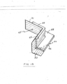
- FIG. 13 shows an angular piece, used to connect the lower transverse plate 26 or upper 40 of the gutter to a longitudinal plate 10 of the figure
- This angular part comprises two elements 64 and 65 connected at right angles.
- the element 64 comprises a longitudinal part 66 and a vertical part 67, perpendicular to the part 66.
- the parts 66 and 67 are arranged respectively in the extension of the longitudinal plate (10) and its vertical lip 36 ( Figure 11 ).
- the element 65 comprises a transverse part 68 and a vertical part 69, perpendicular to the part 68.
- the parts 68 and 69 are arranged in the extension of the lower transverse plate 26 or upper 40.
- the ends 70 and 71 of the elements 65 and 66 are leveled, as explained above, with reference to the Figure 12 .
Landscapes
- Engineering & Computer Science (AREA)
- Architecture (AREA)
- Civil Engineering (AREA)
- Structural Engineering (AREA)
- Roof Covering Using Slabs Or Stiff Sheets (AREA)
Applications Claiming Priority (1)
| Application Number | Priority Date | Filing Date | Title |
|---|---|---|---|
| BE20230091A BE1032213B1 (fr) | 2023-12-12 | 2023-12-12 | Chéneau universel pour l'écoulement des eaux pluviales à la périphérie d'une structure de toit et toiture à pan incliné comprenant une structure de toit incorporant un tel chéneau à sa périphérie |
Publications (1)
| Publication Number | Publication Date |
|---|---|
| EP4571007A1 true EP4571007A1 (de) | 2025-06-18 |
Family
ID=89723014
Family Applications (1)
| Application Number | Title | Priority Date | Filing Date |
|---|---|---|---|
| EP24000142.0A Pending EP4571007A1 (de) | 2023-12-12 | 2024-12-04 | Universaler regenwasserablauf für den rand einer dachstruktur und geneigtes dach mit einer dachstruktur mit einem solchen rand |
Country Status (2)
| Country | Link |
|---|---|
| EP (1) | EP4571007A1 (de) |
| BE (1) | BE1032213B1 (de) |
Citations (4)
| Publication number | Priority date | Publication date | Assignee | Title |
|---|---|---|---|---|
| EP0148429B1 (de) * | 1983-12-24 | 1988-10-19 | Handel & Mack GmbH & Co. KG | Eindeckrahmen |
| NL1008048C2 (nl) * | 1998-01-16 | 1999-07-19 | Ubbink Nederland Bv | Verholen goot. |
| EP1070182B1 (de) * | 1998-04-07 | 2002-06-12 | VKR Holding A/S | Dichtungselement und rahmen für ein das dach durchdringendes bauelement |
| EP1485547B1 (de) * | 2002-03-07 | 2011-10-12 | VKR Holding A/S | Anschlussausrüstung |
-
2023
- 2023-12-12 BE BE20230091A patent/BE1032213B1/fr active IP Right Grant
-
2024
- 2024-12-04 EP EP24000142.0A patent/EP4571007A1/de active Pending
Patent Citations (4)
| Publication number | Priority date | Publication date | Assignee | Title |
|---|---|---|---|---|
| EP0148429B1 (de) * | 1983-12-24 | 1988-10-19 | Handel & Mack GmbH & Co. KG | Eindeckrahmen |
| NL1008048C2 (nl) * | 1998-01-16 | 1999-07-19 | Ubbink Nederland Bv | Verholen goot. |
| EP1070182B1 (de) * | 1998-04-07 | 2002-06-12 | VKR Holding A/S | Dichtungselement und rahmen für ein das dach durchdringendes bauelement |
| EP1485547B1 (de) * | 2002-03-07 | 2011-10-12 | VKR Holding A/S | Anschlussausrüstung |
Also Published As
| Publication number | Publication date |
|---|---|
| BE1032213A1 (fr) | 2025-07-04 |
| BE1032213B1 (fr) | 2025-07-07 |
Similar Documents
| Publication | Publication Date | Title |
|---|---|---|
| FR2466581A1 (fr) | Latte pour toiture | |
| FR2572756A1 (fr) | Paroi composee de panneaux, notamment pour recouvrir des murs de batiments commerciaux et industriels | |
| EP3263797B1 (de) | Dachfenster sowie eine schrägdachstruktur | |
| FR2538434A1 (fr) | Lucarne de couverture avec dispositif d'etancheite | |
| EA037873B1 (ru) | Гидроизолирующий набор, включающий уплотнительный элемент для использования между гидроизолирующим элементом и кровельным материалом, и способ для защиты от погодных условий стыка между крышей здания и проникающей кровельной конструкцией | |
| EP0354149A1 (de) | Verfahren und Vorrichtung zum dichten Verbinden von Beregnung ausgesetzten Platten | |
| BE1032213B1 (fr) | Chéneau universel pour l'écoulement des eaux pluviales à la périphérie d'une structure de toit et toiture à pan incliné comprenant une structure de toit incorporant un tel chéneau à sa périphérie | |
| FR3122682A1 (fr) | Profilé support de toiture comprenant une structure de chéneau et construction de type véranda ou pergola intégrant un tel profilé | |
| BE898300A (fr) | Organe d'étanchéité pour toiture et toiture munie de ces organes. | |
| EP3712344B1 (de) | Belüfteter firstverschluss für dach | |
| EP0596818B1 (de) | Trauf-Dacheindeckungselement für ein Gebäudedach | |
| FR2478706A1 (fr) | Panneau-support pour elements de couverture | |
| EP3012381B1 (de) | Fenster zum einbau in ein dach | |
| EP0657601A1 (de) | Vorrichtung zum Verlegen von Fliesen auf einem vertikalen Rahmen aus Holz oder Metall | |
| BE1019334A3 (fr) | Caisson de toiture autoportant. | |
| EP0127542B1 (de) | Modularer wärmeisolierender Baublock mit einer Verkleidung und Verfahren zum Herstellen eines Gebäudes | |
| EP0255533A1 (de) | Ziegeleindeckung. | |
| EP3652390B1 (de) | Verandastruktur | |
| WO2021209716A1 (fr) | Bande de doublis pour couverture de toit | |
| FR2470216A1 (fr) | Profiles de raccordement du type solin | |
| FR2799780A1 (fr) | Elements de coffrage perdu pour la coulee du beton | |
| FR2525655A1 (fr) | Procede de construction de maisons et de batiments utilitaires | |
| JP2001262780A (ja) | 棟構造 | |
| FR2528894A1 (fr) | Profil d'angle pour revetement de facade | |
| WO2005017284A1 (fr) | Ensemble de parement d'un mur |
Legal Events
| Date | Code | Title | Description |
|---|---|---|---|
| PUAI | Public reference made under article 153(3) epc to a published international application that has entered the european phase |
Free format text: ORIGINAL CODE: 0009012 |
|
| STAA | Information on the status of an ep patent application or granted ep patent |
Free format text: STATUS: THE APPLICATION HAS BEEN PUBLISHED |
|
| AK | Designated contracting states |
Kind code of ref document: A1 Designated state(s): AL AT BE BG CH CY CZ DE DK EE ES FI FR GB GR HR HU IE IS IT LI LT LU LV MC ME MK MT NL NO PL PT RO RS SE SI SK SM TR |
|
| STAA | Information on the status of an ep patent application or granted ep patent |
Free format text: STATUS: REQUEST FOR EXAMINATION WAS MADE |
|
| 17P | Request for examination filed |
Effective date: 20251211 |
|
| GRAP | Despatch of communication of intention to grant a patent |
Free format text: ORIGINAL CODE: EPIDOSNIGR1 |
|
| STAA | Information on the status of an ep patent application or granted ep patent |
Free format text: STATUS: GRANT OF PATENT IS INTENDED |
|
| RIC1 | Information provided on ipc code assigned before grant |
Ipc: E04D 13/02 20060101AFI20260105BHEP Ipc: E04D 13/147 20060101ALI20260105BHEP |
|
| INTG | Intention to grant announced |
Effective date: 20260127 |