EP4570097A1 - Aerosolerzeugungsvorrichtung und vorrichtung zur erkennung und steuerung einer beweglichen abdeckung dafür - Google Patents
Aerosolerzeugungsvorrichtung und vorrichtung zur erkennung und steuerung einer beweglichen abdeckung dafür Download PDFInfo
- Publication number
- EP4570097A1 EP4570097A1 EP23854291.4A EP23854291A EP4570097A1 EP 4570097 A1 EP4570097 A1 EP 4570097A1 EP 23854291 A EP23854291 A EP 23854291A EP 4570097 A1 EP4570097 A1 EP 4570097A1
- Authority
- EP
- European Patent Office
- Prior art keywords
- movable cover
- detection
- control device
- capacitance
- electrode
- Prior art date
- Legal status (The legal status is an assumption and is not a legal conclusion. Google has not performed a legal analysis and makes no representation as to the accuracy of the status listed.)
- Pending
Links
Images


Classifications
-
- A—HUMAN NECESSITIES
- A24—TOBACCO; CIGARS; CIGARETTES; SIMULATED SMOKING DEVICES; SMOKERS' REQUISITES
- A24F—SMOKERS' REQUISITES; MATCH BOXES; SIMULATED SMOKING DEVICES
- A24F40/00—Electrically operated smoking devices; Component parts thereof; Manufacture thereof; Maintenance or testing thereof; Charging means specially adapted therefor
- A24F40/40—Constructional details, e.g. connection of cartridges and battery parts
-
- A—HUMAN NECESSITIES
- A24—TOBACCO; CIGARS; CIGARETTES; SIMULATED SMOKING DEVICES; SMOKERS' REQUISITES
- A24F—SMOKERS' REQUISITES; MATCH BOXES; SIMULATED SMOKING DEVICES
- A24F40/00—Electrically operated smoking devices; Component parts thereof; Manufacture thereof; Maintenance or testing thereof; Charging means specially adapted therefor
- A24F40/50—Control or monitoring
- A24F40/51—Arrangement of sensors
-
- A—HUMAN NECESSITIES
- A24—TOBACCO; CIGARS; CIGARETTES; SIMULATED SMOKING DEVICES; SMOKERS' REQUISITES
- A24F—SMOKERS' REQUISITES; MATCH BOXES; SIMULATED SMOKING DEVICES
- A24F40/00—Electrically operated smoking devices; Component parts thereof; Manufacture thereof; Maintenance or testing thereof; Charging means specially adapted therefor
- A24F40/50—Control or monitoring
- A24F40/53—Monitoring, e.g. fault detection
-
- G—PHYSICS
- G01—MEASURING; TESTING
- G01B—MEASURING LENGTH, THICKNESS OR SIMILAR LINEAR DIMENSIONS; MEASURING ANGLES; MEASURING AREAS; MEASURING IRREGULARITIES OF SURFACES OR CONTOURS
- G01B7/00—Measuring arrangements characterised by the use of electric or magnetic techniques
- G01B7/003—Measuring arrangements characterised by the use of electric or magnetic techniques for measuring position, not involving coordinate determination
-
- A—HUMAN NECESSITIES
- A24—TOBACCO; CIGARS; CIGARETTES; SIMULATED SMOKING DEVICES; SMOKERS' REQUISITES
- A24F—SMOKERS' REQUISITES; MATCH BOXES; SIMULATED SMOKING DEVICES
- A24F40/00—Electrically operated smoking devices; Component parts thereof; Manufacture thereof; Maintenance or testing thereof; Charging means specially adapted therefor
- A24F40/20—Devices using solid inhalable precursors
Definitions
- the present invention relates to the field of atomization technology, and particularly to an aerosol generation device, and a detection and control device for a movable cover thereof.
- An aerosol generation device is an electronic device which atomizes an atomization medium to form an aerosol that can be inhaled by a user, and is configured to heat the atomization medium at a low temperature (usually 350 degrees Celsius) to form the aerosol. Such a heating mode can prevent the generated aerosol from containing ingredients and/or odors that the user does not need, and accordingly is favored by a wide range of users.
- the aerosol generation device is generally provided with a movable cover configured to cover an atomization medium receiving cavity. The switching of operation modes of the aerosol generation device is achieved by detecting and determining a moving position and an action of the movable cover.
- a detection and control device for a movable cover of an aerosol generation device including: a detection electrode, configured to generate a capacitance change according to a relative position relationship between the detection electrode and the movable cover of the aerosol generation device; and a main control device, connected to the detection electrode and configured to analyze a position state of the movable cover according to a detected capacitance and control the aerosol generation device according to the position state of the movable cover.
- the position state of the movable cover includes a closed state and an open state
- the main control device is configured to control the aerosol generation device to enter a low-power consumption dormant state when determining that the movable cover is in the closed state according to the capacitance change
- the main control device is configured to control the aerosol generation device to enter a standby operation state when determining that the movable cover is in the open state according to the capacitance change.
- the open state comprises a completely open state and an opening in progress state
- the main control device is configured to determine that the movable cover is in the opening in progress state when detecting that a capacitance changes from a first capacitance to a second capacitance, and control the aerosol generation device to enter the standby operation state
- the main control device is configured to determine that the movable cover is in the completely open state when detecting that the capacitance changes from the first capacitance to a third capacitance, and control the aerosol generation device to enter a heating operation state or the standby operation state.
- the closed state comprises a completely closed state and a closing in progress state
- the main control device is configured to determine that the movable cover is in the closing in progress state when detecting that a capacitance changes from a third capacitance to a second capacitance, and control the aerosol generation device to maintain a current operation state
- the main control device is configured to determine that the movable cover is in the completely closed state when detecting that the capacitance changes from the second capacitance to a first capacitance, and control the aerosol generation device to enter the low-power consumption dormant state.
- the detection electrode and a movable cover electrode plate form parallel electrode plates.
- the detection electrode is a segmented-type electrode plate or is a linear electrode plate.
- the number of the detection electrodes is more than two, the detection electrodes form parallel electrode plates, and the movable cover is located between or outside the parallel electrode plates.
- each detection electrode among the parallel electrode plates is a segmented-type electrode plate or a linear electrode plate.
- the main control device comprises a detection unit and a main control unit, and the detection unit is configured to be connected to the detection electrode and the main control unit.
- the detection electrode is configured to be connected to an input port of the detection unit, and the movable cover electrode plate is configured to be connected to a power ground or an output port of the detection unit.
- the detection electrode is configured to be connected to a power ground or an output port of the detection unit, and the movable cover electrode plate is configured to be connected to an input port of the detection unit.
- the detection electrode is a segmented-type electrode plateand is connected to a power ground and an input port of the detection unit respectively.
- the detection electrode is a segmented-type electrode plate and is connected to an output port and an input port of the detection unit respectively.
- the main control device is configured to pre-store a corresponding relationship between different positions of the movable cover and capacitance, and determine the current position state of the movable cover by searching the corresponding relationship after an actual capacitance is detected by the detection unit.
- an aerosol generation device including the above-mentioned detection and control device for the movable cover.
- connection in the following embodiments should be regarded as “electrical connection”, “communication connection”, etc., if there exist electrical signals or data transmissions among the connected circuits, modules, units, etc.
- the aerosol generation device known to the applicant generally detects the position of the movable cover with the aid of a Hall sensor.
- the circuit design of this type of technical solution requires that the Hall sensor is directly distributed at a relevant position near the movable cover.
- the functionality of the device is not high, the structural space occupancy is large, the mechanical design is complex, and the reliability is low.
- the present application provides an aerosol generation device, and a detection and control device for a movable cover thereof.
- a detection electrode is introduced, which generates a capacitance change according to a relative position relationship between the detection electrode and a movable cover of the aerosol generation device.
- a main control device is connected to the detection electrode, analyzes a position state of the movable cover according to the detected capacitance, and controls the aerosol generation device according to the position state of the movable cover. Accordingly, a non-contact detection of the position state of the movable cover can be implemented by monitoring the capacitance change, which simplifies the structural design and the circuit, reduces the number of materials, improves the functionality of the device, improves safety, and provides a better interactive experience.
- the aerosol generation device may further include a device housing which is provided with an atomization medium receiving cavity configured to receive the atomization medium.
- the movable cover is configured to cover the atomization medium receiving cavity and can be moved back and forth directionally on a surface of the device housing to implement dust-proof and water vapor-proof functions.
- the atomization medium is a solid medium for generating an aerosol when heated.
- the atomization medium may include a tobacco material, or an aroma component may be further added into the tobacco material.
- the aerosolization medium contains a volatile tobacco flavor compound which is released from a substrate upon heating.
- the atomization medium may also be a liquid medium which is heated and atomized to form the aerosol.
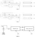
- a detection and control device for a movable cover of an aerosol generation device may include a detection electrode 110 and a main control device 120.
- the main control device 120 is connected to the detection electrode 110.
- the detection electrode 110 generates a capacitance change according to a relative position relationship between the detection electrode and the movable cover 210 of the aerosol generation device.
- the main control device 120 analyzes a position state of the movable cover 210 according to a detected capacitance, and controls the aerosol generation device according to the position state of the movable cover 210.
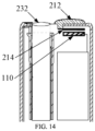
- the aerosol generation device may further include a device housing 220 configured to mount the movable cover 210 and the detection electrode 110, and receive the main control device 120.
- the device housing 220 is provided with an atomization medium receiving cavity 230, and the movable cover 210 can directionally move back and forth on the surface of the device housing 220 (e.g., a linear motion or a rotation around a central axis) to close or open an atomization medium insertion port 232 of the atomization medium receiving cavity 230.
- the movable cover 210 may specifically include a movable cover outer cover 212 located on a side of the device housing 220 (in an embodiment, on an outer surface of the housing, or in other embodiments, may also be partially or completely received in one end of the housing) and a structural portion located inside the device housing 220, both of which may be formed as a one-piece structural assembly or may be discrete structural assemblies.
- the movable cover 210 may be completely or partially of a metal structure, and a metal structure portion of the movable cover 210 may serve as a movable cover electrode plate 214.
- the detection electrode 110 may be fixed to an inner surface of the device housing 220, or may be provided at other positions inside the device housing 220, as long as the detection electrode can generate the capacitance change according to a relative position relationship between the detection electrode and the movable cover electrode plate 214. In the embodiment, the detection electrode 110 is fixed to the inner surface of the device housing 220 at a position corresponding to the movable cover 210.
- the detection electrode 110 may include one or more groups of parallel electrode plates, or form one or more groups of parallel electrode plates with the movable cover electrode plate 214.
- a parallel capacitor may be formed among a plurality of detection electrodes 110, or a parallel capacitor may be formed between the detection electrode 110 and the movable cover electrode plate 214.
- Case 1 a parallel capacitor is formed between the movable cover electrode plate 214 and the detection electrode 110.
- a material and spacing of the electrode plates are constant, and the capacitance C is positively correlated with the relative area S between the electrode plates. Based on this, the relative position of the movable cover 210 with respect to the detection electrode 110 can be reflected.
- Case 2 a parallel capacitor is formed between the detection electrodes 110.
- the material and relative area of the electrode plates are constant.
- the movable cover electrode plate 214 enters between the detection electrodes 110 as a third electrode, which is equivalent to changing the distance between the electrode plates.
- the capacitance C is negatively correlated with the distance d between the electrode plates. Based on this, the relative position of the movable cover 210 with respect to the detection electrode 110 can be reflected.
- Case 3 the parallel capacitor formed between the detection electrodes 110 has an edge effect.
- the edge effect of the electrode plate can be changed.
- the capacitance C is correlated with the edge effect of the electrode plate. Based on this, the relative position of the movable cover 210 with respect to the detection electrode 110 can be reflected.
- the detection and control device for the movable cover may further include a detection electrode carrier 130.
- the detection electrode 110 is provided on the detection electrode carrier 130.
- the detection electrode carrier 130 may be fixed inside the device housing 220, and the detection electrode 110 may be provided on the detection electrode carrier 130, in order to facilitate the mounting and fixation of the detection electrode 110.
- the relative position relationship between the movable cover electrode plate 214 and the detection electrode 110 may change, thereby generating a capacitance change which is detected by the main control device 120, and the main control device 120 may then perform a relevant operation or response according to the capacitance change.
- the main control device 120 can pre-store a corresponding relationship between different positions of the movable cover 210 and capacitances. After the actual capacitance is detected, the current position state of the movable cover 210 can be determined by searching the corresponding relationship, and then the aerosol generation device is controlled according to the current position state of the movable cover 210.
- the aerosol generation device when it is detected that the movable cover 210 is in a closed state (i.e., the atomization medium insertion port 232 is closed), the aerosol generation device is controlled to be in a low-power consumption dormant state.
- the aerosol generation device is controlled to enter a standby operation state or a heating operation state. It should be appreciated that operating parameters of the aerosol generation device in different states can be preset, which will not be described in detail here.
- the detection electrode 110 generates the capacitance change according to the relative position relationship between the detection electrode and the movable cover 210 of the aerosol generation device, and the main control device 120 analyzes the position state of the movable cover 210 according to the detected capacitance, and controls the aerosol generation device according to the position state of the movable cover 210.
- the non-contact detection of the position state of the movable cover 210 is implemented by monitoring the capacitance change, the detection reliability is high, the detection structure is simplified, and the space occupancy rate is reduced.
- the specific structure of the detection electrode 110, and the position relationship between the detection electrode and the movable cover electrode plate 214 are not unique.
- the detection electrodes 110 may be distributed in a moving direction of the movable cover 210.
- the movable cover electrode plate 214 serves as the third plate, the relative position of the movable cover electrode plate 214 with respect to the detection electrodes 110 may be outside the detection electrodes 110, or between the detection electrodes 110.
- the detection electrode 110 may be designed in a linear distribution mode or a segmented-type distribution mode, and the edge of the detection electrode 110 may be straight, or regular zigzag, wavy, circular, trapezoidal, or the like.
- the detection electrode 110 may be designed in a linear distribution mode.
- the detection electrode 110 and the movable cover electrode plate 214 form parallel electrode plates, and the detection electrode 110 is a linear electrode plate.
- the detection electrode 110 may also be designed in a segmented-type distribution mode.
- the detection electrode 110 and the movable cover electrode plate 214 form parallel electrode plates, and the detection electrode 110 is a segmented-type electrode plate.
- the detection electrodes 110 can be designed in a linear distribution mode.
- the number of detection electrodes 110 is more than two and these detection electrodes form parallel electrode plates
- the movable cover electrode plate 214 is located between or outside the parallel electrode plates
- each detection electrode 110 among the parallel electrode plates is a linear electrode plate.
- the detection electrodes 110 may also be designed in a segmented-type distribution mode.
- the number of detection electrodes 110 is more than two and these detection electrodes form parallel electrode plates
- the movable cover electrode plate 214 is located between or outside the parallel electrode plates
- each detection electrode 110 among the parallel electrode plates is the segmented-type electrode plate.
- the main control device 120 includes a detection unit 122 and a main control unit 124.
- the detection unit 122 is connected to the detection electrode 110 and the main control unit 124.
- the detection unit 122 may be a discrete capacitance detection device (such as a touch chip or a capacitance sensor chip, etc.) electrically connected to the main control unit 124, or may be a main control chip with a built-in capacitance detection module in the main control unit 124.
- the detection unit 122 converts the capacitance change into an electrical quantity, such as a voltage, a current, a resistance, a frequency, a phase, etc., and then the main control unit 124 processes the electrical quantity data output by the detection unit 122 to determine the position state of the movable cover 210.
- the main control device 120 may further include a heating unit and/or a power supply module connected to the main control unit 124.
- the capacitance detection principle of the detection unit 122 includes a mutual capacitance detection and a self-capacitance detection. As shown in FIG. 6 , for the self-capacitance detection mode, one electrode plate or a group of electrode plates are fixedly connected to power ground, and another electrode plate or another group of electrode plates are electrically connected to the detection unit 122.
- the detection electrode 110 and the movable cover electrode plate 214 may be equivalent to a self-capacitor Cs.
- a capacitance value of the self-capacitor is detected by the detection unit 122, and the main control unit 124 may perform a corresponding operation or response according to a change in the detection value. As shown in FIG.
- all electrode plates are electrically connected to the detection unit 122 and are not connected to the power ground.
- the detection electrode 110 and the movable cover electrode plate 214 may be equivalent to a mutual capacitor Cm.
- a capacitance value of the mutual capacitor is detected by the detection unit 122, and the main control unit 124 may perform a corresponding operation or response according to a change in the detection value.
- the detection electrode 110 is connected to an input port of the detection unit 122, and the movable cover electrode plate 214 is connected to the power ground or an output port of the detection unit 122. In other embodiments, the detection electrode 110 may be connected to the power ground or the output port of the detection unit 122, and the movable cover electrode plate 214 may be connected to the input port of the detection unit 122. Furthermore, in an embodiment, the detection electrode 110 is the segmented-type electrode plate and is connected to the power ground and the input port of the detection unit 122 respectively. In other embodiments, the detection electrode 110 is the segmented-type electrode plate and is connected to the output port of the detection unit 122 and the input port of the detection unit 122 respectively.
- the detection electrode 110 may be connected to the input port of the detection unit 122, and the movable cover electrode plate 214 may be connected to the power ground.
- the movable cover electrode plate 214 may be connected to the input port of the detection unit 122, and the detection electrode 110 may be connected to the power ground.
- the detection electrode 110 may be connected to the input port of the detection unit 122 and the power ground respectively.
- the mutual capacitance detection mode as shown in FIG.
- the movable cover electrode plate 214 may be connected to the output port of the detection unit 122, and the detection electrode 110 may be connected to the input port of the detection unit 122.
- the detection electrode 110 may be connected to the output port of the detection unit 122, and the movable cover electrode plate 214 may be connected to the input port of the detection unit 122.
- the detection electrode 110 when the detection electrode 110 is the segmented-type electrode plate, the detection electrode 110 may be connected to the output port and the input port of the detection unit 122 respectively.
- part of the detection electrodes 110 may be connected to the input port of the detection unit 122, and part of the detection electrodes 110 may be connected to the power ground.
- part of the detection electrodes 110 may be connected to the output port of the detection unit 122, and part of the detection electrodes 110 may be connected to the input port of the detection unit 122.
- the control mode in which the main control device 120 controls the aerosol generation device according to the position state of the movable cover 210 is not unique.
- the position state of the movable cover 210 includes a closed state and an open state.
- the main control device 120 controls the aerosol generation device to enter a low-power consumption dormant state.
- the main control device 120 controls the aerosol generation device to enter a standby operation state.
- a position where the movable cover 210 covers in place i.e., the movable cover 210 completely covers the atomization medium insertion port 232
- a position 1 A position of the movable cover 210 between the position where the movable cover covers in place and a position where the movable cover opens in place is defined as a position 2 (i.e., the movable cover 210 partially covers the atomization medium insertion port 232, or the movable cover 210 does not covers the atomization medium insertion port 232 absolutely and the movable cover 210 can still move to a position away from the atomization medium insertion port 232).
- a position where the movable cover 210 opens in place is defined as a position 3 (i.e., the movable cover 210 does not covers the atomization medium insertion port 232 absolutely, but the movable cover 210 cannot continue to move in a direction away from the atomization medium insertion port 232). It should be appreciated that stoppers can be provided on the housing corresponding to the position 1 and the position 3 of the movable cover 210 to limit the movable cover 210 to the position 1 and the position 3.
- a capacitance detection value when the movable cover 210 is in position 1 is equal to a first capacitance C1
- the capacitance detection value when the movable cover 210 is in position 2 is equal to a second capacitance C2
- the capacitance detection value when the movable cover 210 is in position 3 is equal to a third capacitance C3.
- the main control unit 124 can perform a corresponding operation according to an actual detected capacitance change. It should be appreciated that a capacitance range at position 1 may be defined as C1
- the capacitance range at position 2 may be defined as C2 correspondingly
- the capacitance range at position 3 may be defined as C3.
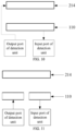
- the main control unit 124 may determine the movable cover 210 as being in the open state. If the aerosol generation device is previously in the low-power consumption dormant state, the main control unit 124 may automatically wake up the aerosol generation device, and display interactive information, then aerosol generation device enters the standby operation state, and the main control unit may monitor a start-up signal in real time such as a button signal or an insertion detection signal of an atomization medium, etc.
- the main control unit 124 determines the movable cover 210 as being in the closed state. If the aerosol generation device is previously in the standby operation state, the main control unit 124 may display the interactive information, and then the aerosol generation device enters the low-power consumption dormant state. If the aerosol generation device is previously in the heating operation state, the main control unit 124 may stop heating and display the interactive information, and then the aerosol generation device enters the low-power consumption dormant state.
- the open state includes a completely open state and an opening in progress state.
- the opening in progress state refers to that the movable cover 210 moves from the position 1 to the position 2, partially covering or absolutely not covering the atomization medium insertion port 232.
- the completely open state refers to that the movable cover 210 moves from the position 1 or the position 2 to the position 3, absolutely does not cover the atomization medium insertion port 232.
- the main control device 120 controls the aerosol generation device to enter the standby operation state.
- the main control device 120 controls the aerosol generation device to enter the heating operation state or the standby operation state.
- the main control unit 124 may determine the movable cover 210 as being in the opening in progress state. If the aerosol generation device is previously in the low-power consumption dormant state, the main control unit 124 may automatically wake up the aerosol generation device, and display the interactive information, and then the aerosol generation device enters the standby operation state, the main control unit may monitor the start-up signal in real time such as a button signal or an insertion detection signal of an atomization medium.
- the atomization medium insertion port 232 is opened.
- the capacitance of the detection electrode 110 changes from C1 to C3.
- the main control unit 124 detects the capacitance change and determines the movable cover 210 as being in the completely open state. If the aerosol generation device is previously in the low-power consumption dormant state, the main control unit 124 may automatically wake up the aerosol generation device, and display the interactive information, and then the aerosol generation device may enter the heating operation state.
- the main control unit 124 may determine the movable cover 210 as being in the completely open state. If the aerosol generation device is previously in the standby operation state, the main control unit 124 may start heating, and display the interactive information, and then the aerosol generation device enters the heating operation state.
- the main control unit 124 may stop heating, and display the interactive information, then the aerosol generation device enters the standby operation state, and the main control unit monitors the start-up signal in real time such as a button signal or an insertion detection signal of an atomization medium.
- the closed state includes a completely closed state and a closing in progress state.
- the closing in progress state refers to that the movable cover 210 moves from the position 3 to the position 2, partially covering or absolutely not covering the atomization medium insertion port 232.
- the completely closed state refers to that the movable cover 210 moves from the position 3 or the position 2 to the position 1, and completely covers the atomization medium insertion port 232.
- the main control device 120 controls the aerosol generation device to maintain the current operation state.
- the main control device 120 controls the aerosol generation device to enter the low-power consumption dormant state.
- the atomization medium insertion port 232 is opened.
- the capacitance of the detection electrode 110 changes from C3 to C2.
- the main control unit 124 monitors the capacitance change, determines the movable cover 210 as being in the closing in progress state, and maintains the previous operation state.
- the main control unit 124 may determine the movable cover 210 as being in the completely closed state. If the aerosol generation device is previously in the standby operation state, the main control unit 124 may display the interactive information, and then the aerosol generation device enters the low-power consumption dormant state. If the aerosol generation device is previously in the heating operation state, the main control unit 124 may stop heating and display the interactive information, and then the aerosol generation device enters the low-power consumption dormant state.
- the main control unit 124 may determine that the movable cover 210 as being in the completely closed state. If the aerosol generation device is previously in the heating operation state, the main control unit 124 may stop heating and display the interactive information, and then the aerosol generation device enters the low-power consumption dormant state.
- an aerosol generation device is further provided, which may include the above-mentioned detection and control device for the movable cover.
- the aerosol generation device may further include a device housing, the device housing is provided with an atomization medium receiving cavity, and the device housing is configured to mount a movable cover and a detection electrode, and receive a main control device. The movable cover can be moved back and forth on a surface of the device housing directionally to close or open the atomization medium insertion port of the atomization medium receiving cavity.
- the non-contact detection of the position state of the movable cover can be implemented by monitoring the capacitance change, accordingly the detection reliability is higher, the detection structure is simplified, and the space occupancy rate is reduced.
Landscapes
- Physics & Mathematics (AREA)
- General Physics & Mathematics (AREA)
- Infusion, Injection, And Reservoir Apparatuses (AREA)
- Details Or Accessories Of Spraying Plant Or Apparatus (AREA)
- Control Of Resistance Heating (AREA)
- Switches That Are Operated By Magnetic Or Electric Fields (AREA)
Applications Claiming Priority (2)
| Application Number | Priority Date | Filing Date | Title |
|---|---|---|---|
| CN202211003418.9A CN115363283B (zh) | 2022-08-19 | 2022-08-19 | 气溶胶生成装置及其活动盖检测控制装置 |
| PCT/CN2023/111857 WO2024037388A1 (zh) | 2022-08-19 | 2023-08-09 | 气溶胶生成装置及其活动盖检测控制装置 |
Publications (2)
| Publication Number | Publication Date |
|---|---|
| EP4570097A1 true EP4570097A1 (de) | 2025-06-18 |
| EP4570097A4 EP4570097A4 (de) | 2025-11-19 |
Family
ID=84066330
Family Applications (1)
| Application Number | Title | Priority Date | Filing Date |
|---|---|---|---|
| EP23854291.4A Pending EP4570097A4 (de) | 2022-08-19 | 2023-08-09 | Aerosolerzeugungsvorrichtung und vorrichtung zur erkennung und steuerung einer beweglichen abdeckung dafür |
Country Status (3)
| Country | Link |
|---|---|
| EP (1) | EP4570097A4 (de) |
| CN (1) | CN115363283B (de) |
| WO (1) | WO2024037388A1 (de) |
Families Citing this family (1)
| Publication number | Priority date | Publication date | Assignee | Title |
|---|---|---|---|---|
| CN115363283B (zh) * | 2022-08-19 | 2026-01-30 | 深圳麦时科技有限公司 | 气溶胶生成装置及其活动盖检测控制装置 |
Family Cites Families (18)
| Publication number | Priority date | Publication date | Assignee | Title |
|---|---|---|---|---|
| JPH10300512A (ja) * | 1997-04-22 | 1998-11-13 | Toyota Motor Corp | 位置センサ |
| US6137403A (en) * | 1998-12-10 | 2000-10-24 | Phoenix Controls Corporation | Sash sensor and method of sensing a sash using an array of multiplexed elements |
| JP6318932B2 (ja) * | 2014-07-14 | 2018-05-09 | 株式会社デンソー | ドア位置検出装置 |
| CN105420995A (zh) * | 2014-08-14 | 2016-03-23 | 松下家电研究开发(杭州)有限公司 | 衣物处理设备的机盖开闭检知方法及其衣物处理设备 |
| KR102231228B1 (ko) * | 2017-05-26 | 2021-03-24 | 주식회사 케이티앤지 | 궐련 삽입 감지 기능을 갖는 에어로졸 생성 장치 및 방법 |
| WO2019012359A1 (en) * | 2017-07-10 | 2019-01-17 | Philip Morris Products S.A. | ENVELOPING ACTIVATION SWITCH FOR AEROSOL GENERATING DEVICES |
| RU2020118125A (ru) * | 2017-12-14 | 2021-12-02 | Джт Интернэшнл С.А. | Электронная сигарета |
| CN108572202B (zh) * | 2018-03-30 | 2020-10-27 | 深圳麦克韦尔科技有限公司 | 一种电子烟状态检测装置、方法及电子烟 |
| WO2020225105A1 (en) * | 2019-05-03 | 2020-11-12 | Jt International S.A. | Aerosol generation device having a moveable closure with a detector |
| EA202192884A1 (ru) * | 2019-05-03 | 2022-03-16 | ДжейТи ИНТЕРНЕШНЛ С.А. | Устройство, генерирующее аэрозоль, с крышкой |
| WO2021088761A1 (zh) * | 2019-11-04 | 2021-05-14 | 黄新凯 | 一次性吸收用品吸收状态监测传感器及相关制品与方法 |
| KR102323511B1 (ko) * | 2020-02-05 | 2021-11-08 | 주식회사 케이티앤지 | 에어로졸 생성 장치 및 그의 동작 방법 |
| CN215347037U (zh) * | 2021-03-03 | 2021-12-31 | 深圳市合元科技有限公司 | 气溶胶生成装置 |
| KR102681871B1 (ko) * | 2021-07-21 | 2024-07-04 | 주식회사 케이티앤지 | 에어로졸 생성 장치 |
| CN114223955B (zh) * | 2021-12-30 | 2024-04-26 | 西安稳先半导体科技有限责任公司 | 一种电子烟 |
| CN114568763B (zh) * | 2022-03-04 | 2026-03-20 | 深圳麦时科技有限公司 | 气溶胶生成装置及其雾化控制装置 |
| CN218483795U (zh) * | 2022-08-19 | 2023-02-17 | 深圳麦时科技有限公司 | 气溶胶生成装置及其活动盖检测装置 |
| CN115363283B (zh) * | 2022-08-19 | 2026-01-30 | 深圳麦时科技有限公司 | 气溶胶生成装置及其活动盖检测控制装置 |
-
2022
- 2022-08-19 CN CN202211003418.9A patent/CN115363283B/zh active Active
-
2023
- 2023-08-09 EP EP23854291.4A patent/EP4570097A4/de active Pending
- 2023-08-09 WO PCT/CN2023/111857 patent/WO2024037388A1/zh not_active Ceased
Also Published As
| Publication number | Publication date |
|---|---|
| CN115363283A (zh) | 2022-11-22 |
| EP4570097A4 (de) | 2025-11-19 |
| CN115363283B (zh) | 2026-01-30 |
| WO2024037388A1 (zh) | 2024-02-22 |
Similar Documents
| Publication | Publication Date | Title |
|---|---|---|
| EP3276458B1 (de) | Elektronischer stift mit wasserdichter struktur | |
| EP4570097A1 (de) | Aerosolerzeugungsvorrichtung und vorrichtung zur erkennung und steuerung einer beweglichen abdeckung dafür | |
| US8090497B2 (en) | Vehicle accessory touch switch | |
| EP4487718A1 (de) | Aerosolerzeugungsvorrichtung und zerstäubungssteuerungsvorrichtung dafür | |
| RU2231108C2 (ru) | Портативный телефон и способ включения электропитания | |
| EP3767733B1 (de) | Aerosolabsaugvorrichtung | |
| EP4548789A1 (de) | Aerosolerzeugungsvorrichtung und sensorsteuerungsvorrichtung dafür | |
| WO2017170224A1 (ja) | タッチパネル付表示装置 | |
| CN218483795U (zh) | 气溶胶生成装置及其活动盖检测装置 | |
| JP3894078B2 (ja) | 電磁調理器 | |
| KR200238102Y1 (ko) | 정전용량형 터치센서 | |
| JP7474824B2 (ja) | 電子ペン | |
| CN100451920C (zh) | 电源管理电路和方法 | |
| CN223515781U (zh) | 气溶胶生成装置 | |
| CN113567751A (zh) | 电子设备 | |
| CN208316780U (zh) | 电子设备 | |
| Wu | A bipolar 1 GHz multi-decade monolithic variable-frequency oscillator | |
| JPS5938481B2 (ja) | 調理器 | |
| CN106911328A (zh) | 一种无按键触摸系统 | |
| KR100494984B1 (ko) | 캐패시턴스 변화를 이용한 자동 디스플레이 제어 장치 및방법 | |
| GB2538815A (en) | Utility meter | |
| KR100423138B1 (ko) | 근접스위치 | |
| Khater | Monitoring and control of evanescent-mode cavity filters | |
| TW200815964A (en) | Circuit and process for power management | |
| HK1227990A1 (en) | Utility meter |
Legal Events
| Date | Code | Title | Description |
|---|---|---|---|
| STAA | Information on the status of an ep patent application or granted ep patent |
Free format text: STATUS: THE INTERNATIONAL PUBLICATION HAS BEEN MADE |
|
| PUAI | Public reference made under article 153(3) epc to a published international application that has entered the european phase |
Free format text: ORIGINAL CODE: 0009012 |
|
| STAA | Information on the status of an ep patent application or granted ep patent |
Free format text: STATUS: REQUEST FOR EXAMINATION WAS MADE |
|
| 17P | Request for examination filed |
Effective date: 20250310 |
|
| AK | Designated contracting states |
Kind code of ref document: A1 Designated state(s): AL AT BE BG CH CY CZ DE DK EE ES FI FR GB GR HR HU IE IS IT LI LT LU LV MC ME MK MT NL NO PL PT RO RS SE SI SK SM TR |
|
| REG | Reference to a national code |
Ref country code: DE Ref legal event code: R079 Free format text: PREVIOUS MAIN CLASS: A24F0040530000 Ipc: A24F0040400000 |
|
| A4 | Supplementary search report drawn up and despatched |
Effective date: 20251022 |
|
| RIC1 | Information provided on ipc code assigned before grant |
Ipc: A24F 40/40 20200101AFI20251016BHEP Ipc: A24F 40/51 20200101ALI20251016BHEP Ipc: A24F 40/53 20200101ALI20251016BHEP Ipc: G01B 7/00 20060101ALI20251016BHEP |
|
| DAV | Request for validation of the european patent (deleted) | ||
| DAX | Request for extension of the european patent (deleted) |