EP4487718A1 - Aerosolerzeugungsvorrichtung und zerstäubungssteuerungsvorrichtung dafür - Google Patents
Aerosolerzeugungsvorrichtung und zerstäubungssteuerungsvorrichtung dafür Download PDFInfo
- Publication number
- EP4487718A1 EP4487718A1 EP22929641.3A EP22929641A EP4487718A1 EP 4487718 A1 EP4487718 A1 EP 4487718A1 EP 22929641 A EP22929641 A EP 22929641A EP 4487718 A1 EP4487718 A1 EP 4487718A1
- Authority
- EP
- European Patent Office
- Prior art keywords
- aerosol generating
- capacitance
- capacitor
- generating substrate
- control device
- Prior art date
- Legal status (The legal status is an assumption and is not a legal conclusion. Google has not performed a legal analysis and makes no representation as to the accuracy of the status listed.)
- Pending
Links
Images


Classifications
-
- A—HUMAN NECESSITIES
- A24—TOBACCO; CIGARS; CIGARETTES; SIMULATED SMOKING DEVICES; SMOKERS' REQUISITES
- A24F—SMOKERS' REQUISITES; MATCH BOXES; SIMULATED SMOKING DEVICES
- A24F40/00—Electrically operated smoking devices; Component parts thereof; Manufacture thereof; Maintenance or testing thereof; Charging means specially adapted therefor
- A24F40/50—Control or monitoring
-
- A—HUMAN NECESSITIES
- A24—TOBACCO; CIGARS; CIGARETTES; SIMULATED SMOKING DEVICES; SMOKERS' REQUISITES
- A24F—SMOKERS' REQUISITES; MATCH BOXES; SIMULATED SMOKING DEVICES
- A24F40/00—Electrically operated smoking devices; Component parts thereof; Manufacture thereof; Maintenance or testing thereof; Charging means specially adapted therefor
- A24F40/10—Devices using liquid inhalable precursors
-
- A—HUMAN NECESSITIES
- A24—TOBACCO; CIGARS; CIGARETTES; SIMULATED SMOKING DEVICES; SMOKERS' REQUISITES
- A24F—SMOKERS' REQUISITES; MATCH BOXES; SIMULATED SMOKING DEVICES
- A24F40/00—Electrically operated smoking devices; Component parts thereof; Manufacture thereof; Maintenance or testing thereof; Charging means specially adapted therefor
- A24F40/20—Devices using solid inhalable precursors
-
- A—HUMAN NECESSITIES
- A24—TOBACCO; CIGARS; CIGARETTES; SIMULATED SMOKING DEVICES; SMOKERS' REQUISITES
- A24F—SMOKERS' REQUISITES; MATCH BOXES; SIMULATED SMOKING DEVICES
- A24F40/00—Electrically operated smoking devices; Component parts thereof; Manufacture thereof; Maintenance or testing thereof; Charging means specially adapted therefor
- A24F40/40—Constructional details, e.g. connection of cartridges and battery parts
- A24F40/46—Shape or structure of electric heating means
-
- A—HUMAN NECESSITIES
- A24—TOBACCO; CIGARS; CIGARETTES; SIMULATED SMOKING DEVICES; SMOKERS' REQUISITES
- A24F—SMOKERS' REQUISITES; MATCH BOXES; SIMULATED SMOKING DEVICES
- A24F40/00—Electrically operated smoking devices; Component parts thereof; Manufacture thereof; Maintenance or testing thereof; Charging means specially adapted therefor
- A24F40/50—Control or monitoring
- A24F40/51—Arrangement of sensors
-
- A—HUMAN NECESSITIES
- A24—TOBACCO; CIGARS; CIGARETTES; SIMULATED SMOKING DEVICES; SMOKERS' REQUISITES
- A24F—SMOKERS' REQUISITES; MATCH BOXES; SIMULATED SMOKING DEVICES
- A24F40/00—Electrically operated smoking devices; Component parts thereof; Manufacture thereof; Maintenance or testing thereof; Charging means specially adapted therefor
- A24F40/50—Control or monitoring
- A24F40/53—Monitoring, e.g. fault detection
-
- A—HUMAN NECESSITIES
- A24—TOBACCO; CIGARS; CIGARETTES; SIMULATED SMOKING DEVICES; SMOKERS' REQUISITES
- A24F—SMOKERS' REQUISITES; MATCH BOXES; SIMULATED SMOKING DEVICES
- A24F47/00—Smokers' requisites not otherwise provided for
-
- G—PHYSICS
- G01—MEASURING; TESTING
- G01R—MEASURING ELECTRIC VARIABLES; MEASURING MAGNETIC VARIABLES
- G01R27/00—Arrangements for measuring resistance, reactance, impedance, or electric characteristics derived therefrom
- G01R27/02—Measuring real or complex resistance, reactance, impedance, or other two-pole characteristics derived therefrom, e.g. time constant
- G01R27/26—Measuring inductance or capacitance; Measuring quality factor, e.g. by using the resonance method; Measuring loss factor; Measuring dielectric constants ; Measuring impedance or related variables
- G01R27/2605—Measuring capacitance
Definitions
- the present disclosure relates to the field of electronic devices, and in particular, to an aerosol generating device and an atomization control device thereof.
- Aerosol generating devices are electronic devices that heat an aerosol generating substrate to form aerosols that can be inhaled by users.
- the aerosol generating devices are popular among users because they do not contain harmful substances such as tar and will not cause any harm to smokers.
- the heating temperature control method will also be different.
- Conventional aerosol generating devices require inputting instructions through buttons to determine a type of the aerosol generating substrate, which is inconvenient to use.
- An atomization control device for an aerosol generating device includes:
- the capacitance processing assembly is further configured to determine a state of the aerosol generating substrate based on the capacitance of the capacitance measuring assembly, and perform heating control on the aerosol generating device based on the state of the aerosol generating substrate.
- the capacitance processing assembly is further configured to control the aerosol generating device to start heating when it is identified that the aerosol generating substrate is inserted based on the capacitance of the capacitance measuring assembly, and control the aerosol generating device to stop heating when it is identified that the aerosol generating substrate is pulled out based on the capacitance of the capacitance measuring assembly.
- the number of the capacitor plates is three or more, and the capacitance processing assembly is configured to control the aerosol generating device to start a preheating stage when the aerosol generating substrate is in a state of being inserted, and control the aerosol generating device to start a heating stage when the aerosol generating substrate is completely inserted.
- the capacitance processing assembly is also configured to control the aerosol generating device to end the heating in advance or reduce a heating temperature when the aerosol generating substrate is in a state of being pulled out.
- the capacitance measuring assembly includes a to-be-measured capacitor, and the to-be-measured capacitor is connected to the capacitance processing assembly.
- the to-be-measured capacitor includes the capacitor plates and a base body made of a non-conductive material, and the capacitor plates are disposed on the base body.
- a number of the capacitor plates is two or more.
- the capacitor plates are closed annular plates or non-closed annular plates.
- the capacitor plates each include an annular portion and an extension portion disposed on the annular portion, the number of the capacitor plates is two, and the extension portions of the two capacitor plates are disposed opposite to each other.
- the base body is a hollow cylindrical base body, and the capacitor plates are located outside or inside of the base body and distributed along a longitudinal direction of the base body.
- the number of the capacitor plates is two, and the capacitor plates are located on a cylindrical inner wall surface or outer wall surface of the base body.
- the number of the capacitor plates is two, one end of the base body is closed to form a bottom wall, and one of the capacitor plates is disposed on the bottom wall of the base body.
- the to-be-measured capacitor further includes a heating element disposed on the base body.
- the capacitor plates form annular plate groups in a one-to-many or many-to-many manner.
- the to-be-measured capacitor includes a base body made of a conductive material, and the base body is divided into two or more capacitor plates.
- the capacitor plates are closed annular plates or non-closed annular plates.
- the to-be-measured capacitor further includes an insulating member disposed between the capacitor plates.
- the capacitor plates and the insulating member are hollow and are configured to receive the aerosol generating substrate together.
- the capacitor plates form annular plate groups in a one-to-many or many-to-many manner.
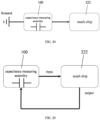
- the capacitance processing assembly includes a capacitance acquisition component and a main control unit, and the capacitance acquisition component is connected to the capacitance measuring assembly and the main control unit.
- An aerosol generating device includes the above-mentioned atomization control device.
- the capacitor plates of the capacitance measuring assembly are distributed along the insertion direction of the aerosol generating substrate.
- the capacitance measuring assembly generates a capacitance change based on whether the aerosol generating substrate is inserted.
- the capacitance processing assembly identifies the type of the aerosol generating substrate based on the capacitance of the capacitance measuring assembly, and determines the heating control mode for the aerosol generating device based on the type of the aerosol generating substrate. In this way, the heating control mode is automatically adjusted based on the type of the aerosol generating substrate without requiring a user to operate buttons, thereby improving the convenience of use.
- connection in the following embodiments should be understood as “electrical connection”, “communication connection”, etc. if the connected circuits, modules, units, etc. have electrical signals or data transmission between each other.
- a capacitance measuring assembly generates a capacitance change based on whether an aerosol generating substrate is inserted.
- a capacitance processing assembly identifies the type of the aerosol generating substrate based on the capacitance of the capacitance measuring assembly, and determines a heating control mode for the aerosol generating device based on the type of the aerosol generating substrate, so that automatic adjustment of the heating control mode based on the type of the aerosol generating substrate is achieved without requiring a user to operate buttons, thereby enhancing human-machine interaction and human experience.
- the capacitance processing assembly further determines a state of the aerosol generating substrate based on the capacitance of the capacitance measuring assembly, and performs heating control on the aerosol generating device based on the state of the aerosol generating substrate, so as to intelligently determine the insertion of the aerosol generating substrate to intelligently start the heating of the aerosol generating substrate, and to intelligently determine the removal of the aerosol generating substrate to intelligently stop the heating of the aerosol generating substrate, that is, stopping the heating immediately upon the removal of the aerosol generating substrate. Additionally, it can avoid misheating when there is no aerosol generating substrate in the aerosol generating device, and prevent dry burning when there is no aerosol generating substrate, thus the device has a certain degree of intelligent safety.
- the aerosol generating substrate is solid substrate configured to generate aerosol when heated.
- the aerosol generating substrate includes tobacco-containing material, and the tobacco-containing material contains volatile tobacco flavor compounds released from the substrate when heated.
- the aerosol generating substrate may include non-tobacco material.
- the solid substrate may contain materials such as herbaceous plant leaves, and tobacco leaves, etc.
- the aerosol generating substrate may also be a liquid substrate, which is atomized to form aerosols when being heated.
- an atomization control device for an aerosol generating device including a capacitance measuring assembly 100 and a capacitance processing assembly 200. Capacitor plates of the capacitance measuring assembly 100 are distributed along an insertion direction of the aerosol generating substrate.
- the capacitance processing assembly 200 is connected to the capacitance measuring assembly 100.
- the capacitance measuring assembly 100 generates a capacitance change based on whether the aerosol generating substrate is inserted.
- the capacitance processing assembly 200 identifies a type of the aerosol generating substrate based on the capacitance of the capacitance measuring assembly 100, and determines a heating control mode for the aerosol generating device based on the type of the aerosol generating substrate.
- the capacitance measuring assembly 100 can be mounted in a cavity for inserting the aerosol generating substrate in the aerosol generating device. When the aerosol generating substrate is inserted into or pulled out of the aerosol generating device by a user, the capacitance of the capacitance measuring assembly 100 changes based on an actual insertion position of the aerosol generating substrate.
- the capacitance processing assembly 200 can pre-store the capacitances of the capacitance measuring assembly 100 when different types of aerosol generating substrates are inserted. After measuring the actual capacitance of the capacitance measuring assembly 100, the type of the currently inserted aerosol generating substrate can be identified, and then the heating control mode for the aerosol generating device can be adjusted based on the type of the aerosol generating substrate.
- the capacitance processing assembly 200 can directly identify the type of the aerosol generating substrate based on the capacitance value range in which the actual capacitance value is located.
- the capacitance processing assembly 200 can further pre-store the heating control modes for different types of aerosol generating substrates, such as heating methods and temperature control methods. After identifying the type of the inserted aerosol generating substrate, the capacitance processing assembly 200 can use different heating methods and temperature control methods based on different types of aerosol generating substrates to enhance human-machine interaction and human experience.
- the capacitance processing assembly 200 is further configured to determine the state of the aerosol generating substrate based on the capacitance of the capacitance measuring assembly, and perform heating control on the aerosol generating device based on the state of the aerosol generating substrate.
- the capacitance processing assembly 200 can pre-store an initial capacitance value of the capacitance measuring assembly 100 as a comparison threshold. After measuring the actual capacitance of the capacitance measuring assembly 100, the capacitance processing assembly 200 can compare the measured actual capacitance of the capacitance measuring assembly 100 with the comparison threshold to determine whether the aerosol generating substrate being in an inserted state or pulled out state, and then perform heating control on the aerosol generating device based on the state of the aerosol generating substrate.
- the capacitance processing assembly 200 controls a power supply module to supply power to start the heating when it is identified that the aerosol generating substrate is inserted.
- the capacitance processing assembly 200 also controls the power supply module to turn off the power to end the heating when it is identified that the aerosol generating substrate is pulled out.
- the number of the capacitor plates of the capacitance measuring assembly 100 is not limited, and may be two, three, or more.
- the capacitance measuring assembly 100 includes two capacitor plates, it is possible to identify whether the aerosol generating substrate being in an inserted state or a pulled out state based on the capacitance of the capacitance measuring assembly 100.
- the capacitance measuring assembly 100 includes three or more capacitor plates, it is possible to identify a present insertion position of the aerosol generating substrate and whether it is in the state of being inserted or being pulled out based on the capacitance of the capacitance measuring assembly 100.
- the mode in which the capacitance processing assembly 200 performs heating control on the aerosol generating device based on the state of the aerosol generating substrate is not limited.
- the capacitance processing assembly 200 controls the aerosol generating device to start heating when it identifies that the aerosol generating substrate is inserted based on the capacitance of the capacitance measuring assembly 100.
- the capacitance processing assembly 200 also controls the aerosol generating device to stop heating when it identifies that the aerosol generating substrate is pulled out based on the capacitance of the capacitance measuring assembly 100.
- the capacitance processing assembly 200 controls the aerosol generating device to start a preheating stage when the aerosol generating substrate is in the state of being inserted, and controls the aerosol generating device to start a heating stage when the aerosol generating substrate is completely inserted.
- the capacitance processing assembly 200 further controls the aerosol generating device to end the heating in advance or reduce the heating temperature when the aerosol generating substrate is in the state of being pulled out. Specifically, based on the measured actual capacitance of the capacitance measuring assembly 100, the capacitance processing assembly 200 determines whether the aerosol generating substrate is in the state of being inserted or being pulled out and an actual present position of the aerosol generating substrate.
- the capacitance processing assembly 200 When the aerosol generating substrate is in the state of being pulled out, the capacitance processing assembly 200 further controls to end the heating in advance or reduce the heating temperature. Furthermore, if the operation of reducing the heating temperature is performed while the aerosol generating substrate is being pulled out, the capacitance processing assembly 200 completely ends the heating when it is identified that the aerosol generating substrate is completely pulled out.
- the capacitance processing assembly 200 includes a capacitance acquisition component 220 and a main control unit 240.
- the capacitance acquisition component 220 connects the capacitance measuring assembly 100 and the main control unit 240.
- An output terminal of the capacitance measuring assembly 100 is connected to an input terminal of the capacitance acquisition component 220.
- the capacitance acquisition component 220 is connected to an input terminal and output terminal of the main control unit 240.
- the capacitance acquisition component 220 may be a touch chip, a 555 timer, an RC circuit, or other circuits that can acquire capacitance.
- the capacitance acquisition component 220 converts the capacitance change into electrical quantities, such as voltage, current, resistance, frequency, phase, etc., and then the main control unit 240 processes the electrical quantity data output by the capacitance acquisition component 220, so as to control the external device.
- the capacitance acquisition component 220 can further include a touch chip and a detection circuit.
- the touch chip is connected to the capacitance measuring assembly 100 through the detection circuit.
- the detection circuit may specifically include a capacitor configured to be connected in series or parallel with the capacitor plate of the capacitance measuring assembly 100.
- the capacitance measuring assembly 100 generates the capacitance change based on whether the aerosol generating substrate is inserted, and the capacitance processing assembly 200 identifies the type of the aerosol generating substrate based on the capacitance of the capacitance measuring assembly 100, and determines the heating control mode for the aerosol generating device based on the type of the aerosol generating substrate, realizing automatic adjustment of the heating control mode based on the type of the aerosol generating substrate without requiring the user to operate buttons, thereby improving the convenience of use.
- the capacitance measuring assembly 100 includes to-be-measured capacitors, and the to-be-measured capacitors are connected to the capacitance processing assembly 200.
- the to-be-measured capacitor can be designed as an annular capacitor.
- the to-be-measured capacitors can be set in a cavity for inserting the aerosol generating substrate in the aerosol generating device.
- the capacitance processing assembly 200 measures the actual capacitance values of the to-be-measured capacitors and compares the measured actual capacitance values with a corresponding preset initial capacitance value to determine whether the capacitance value of each to-be-measured capacitor has changed, thereby obtaining the present position of the aerosol generating substrate and whether the aerosol generating substrate is in a state of being inserted state or being pulled out.
- the capacitance processing assembly 200 can further directly identify the type of the aerosol generating substrate based on the capacitance value range in which the actual capacitance value of the to-be-measured capacitor is located.
- the to-be-measured capacitor includes capacitor plates and a base body made of a non-conductive material, and the capacitor plates are arranged on the base body.
- the number of the capacitor plates is two or more. In the insertion direction of the aerosol generating substrate (for example, when inserted vertically), the two or more capacitor plates are located at different horizontal heights.
- the capacitor plates are closed annular plates or non-closed annular plates.
- the base body can be designed as a hollow cylindrical base body and is configured to receive the aerosol generating substrate.
- Each of the capacitor plates surrounds the base body, and specifically, the capacitor plates are located outside or inside of the base body and distributed along the longitudinal direction of the base body. In an embodiment, the number of the capacitor plates is two, and the capacitor plates are located on a cylindrical inner wall or outer wall of the base body.
- the cylindrical base body can be designed to be open at both ends, and then the capacitor plates are arranged on the cylindrical inner wall or outer wall of the base body.
- the capacitor plate can be a metal plate, which can be a flexible plate or an electroplated plate.
- the profile of the annular capacitor plate can be circular, rectangular, arched, triangular, spiral, or a composite of these shapes.
- the edges of the two ends of the capacitor plate can be one or more sections of linear, nonlinear, planar, or non-planar.
- capacitor plate A and capacitor plate B may be provided on a non-conductive base body 10 by laminating, coating, or electroplating.
- the capacitor plate A and the capacitor plate B form an equivalent capacitor.
- Each capacitor plate may have a closed structure or a non-closed structure, or may be any combination of a closed annular plate and a non-closed annular plate.
- the capacitor plates form annular plate groups in a one-to-many or many-to-many manner.
- the two capacitor plates form an annular plate group.
- the capacitor plates can form annular plate groups in a one-to-many or many-to-many manner.
- the capacitor plate A and the capacitor plate B form a group of electrodes
- the capacitor plate A and the capacitor plate C form a group of electrodes
- the capacitor plate A and the capacitor plate D form a group of electrodes.
- It can also be many-to-many, as shown in FIG. 6 the capacitor plate A and the capacitor plate C form a group of electrodes
- the capacitor plate B and the capacitor plate D form a group of electrodes.
- a capacitor plate can also be set at the bottom of the base body 10 as a bottom plate, and the bottom plate and other corresponding capacitor plates form equivalent capacitors.
- the shape of the bottom plate is not limited, and can be rectangular, circular, triangular, arched, spiral, and a composite of these shapes.
- FIG. 7 there is a bottom plate E at the bottom of the base body 10, and the bottom plate E and annular capacitor plates form one or more equivalent capacitors.
- the capacitor plate A and the bottom plate E constitute an equivalent capacitor.
- the capacitor plate A and the bottom plate E constitute an equivalent capacitor
- the capacitor plate B and the bottom plate E constitute an equivalent capacitor
- the capacitor plate C and the bottom plate E constitute an equivalent capacitor
- the capacitor plate D and the bottom plate E constitute an equivalent capacitor.
- the number of the capacitor plates is two, one end of the base body 10 is closed to form a bottom wall, and one of the capacitor plates is disposed on the bottom wall of the base body 10.
- two capacitor plates are disposed longitudinally inside the base body 10, one of which is located on the bottom wall of the base body 10 as a bottom plate, and the other capacitor plate is located on the side wall of the base body 10.
- the to-be-measured capacitor may also include a heating element disposed on the base body 10.
- the heating element may be a resistive heat generating line printed on the base body 10, and is configured to heat the aerosol generating substrate.
- the capacitor plate includes an annular portion and an extension portion disposed on the annular portion.
- the number of the capacitor plates is two, and the extension portions of the two capacitor plates are disposed opposite to each other.
- the capacitor plate A and the capacitor plate B are each designed to be a structure consisting of an annular portion and an extension portion, the extension portion of the capacitor plate is disposed on the annular portion and is perpendicular to the curved surface where the annular portion is located, and the extension portions of the two capacitor plates are disposed opposite to each other.
- the to-be-measured capacitor includes a base body 10 made of a conductive material.
- the base body 10 is divided into two or more capacitor plates, and can be specifically divided into three capacitor plates.
- the capacitor plates form annular plate groups in a one-to-many or many-to-many manner.
- the base body 10 serves as both a heating element and a capacitor plate.
- the base body 10 is divided into a plurality of annular capacitor plates, and as shown in FIG. 10 and FIG. 11 , the capacitor plate A and the capacitor plate B formed by the division of the base body 10 form an equivalent capacitor.
- Each capacitor plate is an annular capacitor plate, which can be closed or non-closed, or any combination of the closed annular plate and the non-closed annular plate.
- the capacitor plate A and the capacitor plate B are both made of metal, and can receive the aerosol generating substrate and generate heat through an external alternating magnetic field, thereby heating the aerosol generating substrate.
- the to-be-measured capacitor also includes an insulating member arranged between the capacitor plates.
- an insulating member 20 is arranged between the capacitor plate A and the capacitor plate B.
- the insulating member 20 may be made of ceramic.
- the capacitor plate and the insulating member 20 are hollow and are configured to receive the aerosol generating substrate together.
- the capacitor plates formed by the division of the base body 10 form a plurality of groups of annular plates, in the form of one-to-many, as shown in FIG. 12 , the capacitor plate A and the capacitor plate B form a group of electrodes, the capacitor plate A and the capacitor plate C form a group, and the capacitor plate A and the capacitor plate D form a group of electrodes. It can also be many-to-many, as shown in FIG. 13 , the capacitor plate A and the capacitor plate C form a group of electrodes, and the capacitor plate B and the capacitor plate D form a group of electrodes.
- a capacitor plate divided from the base body 10 can also be used as the bottom plate of the base body 10, and the bottom plate and other corresponding capacitor plates form equivalent capacitors.
- the shape of the bottom plate can also be rectangular, circular, triangular, arched, spiral, and a composite of these shapes.
- FIG. 14 there is a bottom plate E at the bottom of the base body 10, and the bottom plate E and the annular capacitor plate form one or more equivalent capacitors.
- the capacitor plate A and the bottom plate E constitute an equivalent capacitor.
- the capacitor plate A and the bottom plate E constitute an equivalent capacitor
- the capacitor plate B and the bottom plate E constitute an equivalent capacitor
- the capacitor plate C and the bottom plate E constitute an equivalent capacitor
- the capacitor plate D and the bottom plate E constitute an equivalent capacitor.
- FIG. 16 is a simplified schematic diagram in which the aerosol generating substrate X is inserted into the base body.
- the aerosol generating substrate X is regarded as a plate of a capacitor.
- the capacitor plate A and the aerosol generating substrate X form a capacitor 1
- the capacitor plate B and the aerosol generating substrate X form a capacitor 2.
- the schematic diagram of the formed equivalent capacitors is shown in FIG. 17 .
- the conductivity of the aerosol generating substrate X is much smaller than the conductivity of the capacitor plate A and the capacitor plate B, when the aerosol generating substrate X is inserted between the capacitor plate A and the capacitor plate B, the dielectric constant ⁇ of the material between the capacitor plate A and the capacitor plate B is changed, causing the capacitance between the capacitor plate A and the capacitor plate B to change.
- the aerosol generating substrate X can be a cigarette, a solid medicine or other solid substances.
- the aerosol generating substrate X can also be a liquid substance contained in a solid container.
- the capacitance corresponding to the annular capacitor plate at the corresponding position can be measured to change, thereby determining the position of the aerosol generating substrate.
- the insertion state and the position of the aerosol generating substrate can be obtained, and then heating can be started, as well as the pulled out state and the position of the aerosol generating substrate can be obtained, and then the heating can be stopped.
- the capacitor plate A and the capacitor plate B form a capacitor
- the capacitor plate A and the capacitor plate C form a capacitor
- the capacitor plate A and the capacitor plate D form a capacitor.
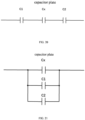
- the capacitance measuring assembly 100 can be categorized into two types: independent measured assembly and composite measured assembly.
- the composite measured assembly can further include a series-type and a parallel-type.
- Cx refers to a capacitor plate.
- capacitor C1 and capacitor C2 are external measured capacitors connected in series with the capacitor plate Cx, and the capacitor C1 and the capacitor C2 are specifically capacitors in the capacitance acquisition component 220.
- the number of the capacitors connected in series with the capacitor plate Cx is not limited, it can be one, two, or more and can be adjusted according to actual needs.
- the capacitors connected in series with the capacitor plate Cx can be finished capacitors produced by a capacitor manufacturer or capacitors composed of structural parts.
- capacitor C1 and capacitor C2 are external measured capacitors connected in parallel with the capacitor plate Cx.
- the capacitor C1 and the capacitor C2 are specifically capacitors in the capacitance acquisition component 220.
- the number of capacitors in parallel with the capacitor plate Cx is not limited, it can also be one, two or more, and can be adjusted according to actual needs.
- the capacitors in parallel with the capacitor plate Cx can be finished capacitors produced by a capacitor manufacturer or capacitors composed of structural parts.
- capacitor C1 and capacitor C2 are external measured capacitors connected in parallel with the capacitor plate Cx
- capacitor C3 and capacitor C4 are external measured capacitors connected in series with the capacitor plate Cx.
- the capacitor C1, the capacitor C2, the capacitor C3 and the capacitor C4 are specifically capacitors in the capacitance acquisition component 220.
- capacitor C3 and capacitor C4 are connected in series with the capacitor plate Cx.
- Capacitor C1, capacitor C2 and the capacitor C3 are connected in parallel.
- the capacitor C1, the capacitor C2, the capacitor C3 and the capacitor C4 are specifically capacitors in the capacitance acquisition component 220.
- the number of capacitors connected in parallel with the capacitor plate Cx is not limited, it can be one, two, or more, and can be adjusted according to actual needs.
- the capacitors connected in parallel with the capacitor plate Cx can be finished capacitors produced by a capacitor manufacturer or capacitors composed of structural parts.
- the number of capacitors connected in series with the capacitor plate Cx is not limited, it can be one, two, or more, and can be adjusted according to actual needs.
- the capacitors connected in series with the capacitor plate Cx can be finished capacitors produced by a capacitor manufacturer or capacitors composed of structural parts.
- a capacitance scanning principle of the touch chip 222 includes mutual capacitance scanning and self-capacitance scanning.
- Self-capacitance scanning is a scanning method of self-transmission and self-reception, and the capacitance measured by the touch chip 222 is the capacitance between an electrode and the ground.
- the touch chip 222 measures the capacitance between two electrodes.
- the connection between the touch chip 222 and the capacitance measuring assembly 100 includes the following two manners. As shown in FIG.
- one of the plates of the to-be-measured capacitor in the capacitance measuring assembly 100 is connected to the ground, and the other plate is connected to a signal acquisition input terminal of the touch chip 222.
- one of the plates of the to-be-measured capacitor in the capacitance measuring assembly 100 is connected to a signal output terminal of the touch chip 222, and the other plate is connected to the signal acquisition input terminal of the touch chip 222.
- An initial capacitance value of the capacitance measuring assembly 100 is periodically acquired and updated by the touch chip 222, and the initial capacitance value is used as the threshold value for determining the capacitance change.
- the touch chip acquires a change of the capacitance value of each group of annular plates.
- the main control unit 240 can determine the position of the aerosol generating substrate and whether it is in the state of being inserted or being pulled out based on the capacitance value measured by the touch chip 222.
- the main control unit 240 may include a control chip and a discrete device.
- the control chip is configured for collecting data information from the touch chip 222 and making control actions based on the data information from the touch chip 222.
- the discrete device includes a power supply chip, a resistor, a capacitor, an inductor, a crystal oscillator, a memory, a logic gate circuit, etc. that support an operation of the control chip.
- the touch chip 222 identifies the state of being inserted gradually based on the capacitance change of the annular capacitor plates at specific positions, and the main control unit 240 can start preheating in advance.
- the touch chip 222 When the aerosol generating substrate is inserted, the touch chip 222 identifies the completely inserted state based on the capacitance change of the annular capacitor plates at specific positions, and the main control unit 240 start the heating stage. Further, by setting capacitance value ranges corresponding to different types of solid aerosol generating substrates, the touch chip 222 identifies different types of the solid aerosol generating substrates based on the acquired capacitance values, and then the main control unit 240 adopts different heating control modes, such as adjusting to a heating method and a temperature control method corresponding to the identified solid aerosol generating substrate when the heating stage is started.
- the touch chip 222 can identify different types of the liquid aerosol generating substrates based on the acquired capacitance values, and then the main control unit 240 can adopt different heating methods and temperature control methods. For example, when the heating stage is started, it is adjusted to the heating method and temperature control method corresponding to the identified liquid aerosol generating substrate.
- the touch chip 222 identifies the state of being pulled out gradually based on the capacitance change of the annular capacitor plates at specific positions, and the main control unit 240 can end the heating in advance or reduce the heating temperature.
- the touch chip 222 identify the completely pulled out state based on the capacitance change of the annular capacitor plates at specific positions, and the main control unit 240 completely ends the heating.
- an aerosol generating device including the above-mentioned atomization control device.
- the capacitance of the capacitance measuring assembly changes based on whether an aerosol generating substrate is inserted.
- the capacitance processing assembly identifies a type of the aerosol generating substrate based on the capacitance of the capacitance measuring assembly, and determines a heating control mode for the aerosol generating device based on the type of the aerosol generating substrate. In this way, the heating control mode is automatically adjusted based on the type of the aerosol generating substrate without requiring a user to operate buttons, thereby improving the convenience of use.
Landscapes
- Physics & Mathematics (AREA)
- General Physics & Mathematics (AREA)
- Fixed Capacitors And Capacitor Manufacturing Machines (AREA)
- Control Of Resistance Heating (AREA)
- Investigating Or Analyzing Materials By The Use Of Electric Means (AREA)
Applications Claiming Priority (2)
| Application Number | Priority Date | Filing Date | Title |
|---|---|---|---|
| CN202210215103.4A CN114568763B (zh) | 2022-03-04 | 2022-03-04 | 气溶胶生成装置及其雾化控制装置 |
| PCT/CN2022/138536 WO2023165214A1 (zh) | 2022-03-04 | 2022-12-13 | 气溶胶生成装置及其雾化控制装置 |
Publications (2)
| Publication Number | Publication Date |
|---|---|
| EP4487718A1 true EP4487718A1 (de) | 2025-01-08 |
| EP4487718A4 EP4487718A4 (de) | 2025-06-25 |
Family
ID=81773058
Family Applications (1)
| Application Number | Title | Priority Date | Filing Date |
|---|---|---|---|
| EP22929641.3A Pending EP4487718A4 (de) | 2022-03-04 | 2022-12-13 | Aerosolerzeugungsvorrichtung und zerstäubungssteuerungsvorrichtung dafür |
Country Status (5)
| Country | Link |
|---|---|
| EP (1) | EP4487718A4 (de) |
| JP (1) | JP2025507933A (de) |
| KR (1) | KR20240135029A (de) |
| CN (1) | CN114568763B (de) |
| WO (1) | WO2023165214A1 (de) |
Families Citing this family (5)
| Publication number | Priority date | Publication date | Assignee | Title |
|---|---|---|---|---|
| CN114568763B (zh) * | 2022-03-04 | 2026-03-20 | 深圳麦时科技有限公司 | 气溶胶生成装置及其雾化控制装置 |
| CN115024522A (zh) * | 2022-07-04 | 2022-09-09 | 深圳麦时科技有限公司 | 气溶胶生成装置及其感应控制装置 |
| CN117461900A (zh) * | 2022-07-22 | 2024-01-30 | 深圳麦克韦尔科技有限公司 | 雾化控制方法及雾化装置 |
| CN115363283B (zh) * | 2022-08-19 | 2026-01-30 | 深圳麦时科技有限公司 | 气溶胶生成装置及其活动盖检测控制装置 |
| CN115644523A (zh) * | 2022-10-19 | 2023-01-31 | 深圳麦时科技有限公司 | 控制方法、控制模块及气溶胶生成装置 |
Family Cites Families (23)
| Publication number | Priority date | Publication date | Assignee | Title |
|---|---|---|---|---|
| ATE543525T1 (de) * | 2009-11-18 | 2012-02-15 | Hoffmann La Roche | Kartuschenerkennung |
| WO2012022771A2 (en) * | 2010-08-19 | 2012-02-23 | Sanofi-Aventis Deutschland Gmbh | Method and system for determining information related to a drug reservoir using an electronic sensor |
| EP4660588A3 (de) * | 2014-03-21 | 2026-03-18 | Nicoventures Trading Limited | Vorrichtung zum erwärmen von rauchbarem material und artikel aus rauchbarem material |
| CN107949288B (zh) * | 2015-09-24 | 2021-08-10 | 菲利普莫里斯生产公司 | 具有电容器的气溶胶生成制品 |
| TW201825827A (zh) * | 2016-12-22 | 2018-07-16 | 瑞士商菲利浦莫里斯製品股份有限公司 | 具有成對電極之氣溶膠產生系統 |
| CN110520004A (zh) * | 2017-04-11 | 2019-11-29 | 韩国烟草人参公社 | 对加热器进行初预热的气溶胶生成系统 |
| GB201805234D0 (en) * | 2018-03-29 | 2018-05-16 | Nicoventures Trading Ltd | Aerosol generating device |
| CN108572202B (zh) * | 2018-03-30 | 2020-10-27 | 深圳麦克韦尔科技有限公司 | 一种电子烟状态检测装置、方法及电子烟 |
| JP7244648B2 (ja) * | 2018-12-17 | 2023-03-22 | フィリップ・モーリス・プロダクツ・ソシエテ・アノニム | マウスピース検出を備えたエアロゾル発生装置 |
| KR102262490B1 (ko) * | 2019-01-16 | 2021-06-08 | 주식회사 케이티앤지 | 에어로졸 생성 장치 및 방법 |
| WO2021006611A2 (ko) * | 2019-07-08 | 2021-01-14 | 주식회사 이엠텍 | 에어로졸 형성기재 감지 기능을 갖는 휴대용 에어로졸 발생장치 및 그 운용방법 |
| KR102337231B1 (ko) * | 2020-02-07 | 2021-12-08 | 주식회사 케이티앤지 | 에어로졸 생성 장치 및 제어 방법 |
| KR102328201B1 (ko) * | 2020-02-07 | 2021-11-17 | 주식회사 케이티앤지 | 에어로졸 생성 장치 및 그 동작 방법 |
| KR102451070B1 (ko) * | 2020-06-03 | 2022-10-05 | 주식회사 케이티앤지 | 외부가열식 에어로졸 생성 장치 |
| CN114073336A (zh) * | 2020-08-11 | 2022-02-22 | 深圳市合元科技有限公司 | 气溶胶生成装置及其方法、系统 |
| KR102502754B1 (ko) * | 2020-08-19 | 2023-02-22 | 주식회사 케이티앤지 | 에어로졸 생성 물품의 삽입 여부를 감지하는 에어로졸 생성 장치 및 그의 동작 방법 |
| CN112056634B (zh) * | 2020-10-10 | 2023-03-14 | 云南中烟工业有限责任公司 | 一种控制电加热烟具加热烟支的方法 |
| CN112315031A (zh) * | 2020-11-20 | 2021-02-05 | 河南中烟工业有限责任公司 | 基于极间电容介电常数变化的烟支检测方法 |
| KR20220111441A (ko) * | 2021-02-02 | 2022-08-09 | 주식회사 이엠텍 | 휴대용 에어로졸 발생장치 |
| CN113892683B (zh) * | 2021-10-08 | 2024-06-28 | 海南摩尔兄弟科技有限公司 | 气溶胶生成品、电子雾化器、雾化系统、识别方法和温度控制方法 |
| CN114568763B (zh) * | 2022-03-04 | 2026-03-20 | 深圳麦时科技有限公司 | 气溶胶生成装置及其雾化控制装置 |
| CN114582631B (zh) * | 2022-03-04 | 2024-08-13 | 深圳麦时科技有限公司 | 用于气溶胶生成装置的待测电容组件 |
| CN114568750A (zh) * | 2022-03-04 | 2022-06-03 | 深圳麦时科技有限公司 | 气溶胶生成装置及其感应控制装置 |
-
2022
- 2022-03-04 CN CN202210215103.4A patent/CN114568763B/zh active Active
- 2022-12-13 WO PCT/CN2022/138536 patent/WO2023165214A1/zh not_active Ceased
- 2022-12-13 JP JP2024552305A patent/JP2025507933A/ja active Pending
- 2022-12-13 KR KR1020247028803A patent/KR20240135029A/ko active Pending
- 2022-12-13 EP EP22929641.3A patent/EP4487718A4/de active Pending
Also Published As
| Publication number | Publication date |
|---|---|
| KR20240135029A (ko) | 2024-09-10 |
| JP2025507933A (ja) | 2025-03-21 |
| CN114568763A (zh) | 2022-06-03 |
| CN114568763B (zh) | 2026-03-20 |
| WO2023165214A1 (zh) | 2023-09-07 |
| EP4487718A4 (de) | 2025-06-25 |
Similar Documents
| Publication | Publication Date | Title |
|---|---|---|
| EP4487718A1 (de) | Aerosolerzeugungsvorrichtung und zerstäubungssteuerungsvorrichtung dafür | |
| EP4548789A1 (de) | Aerosolerzeugungsvorrichtung und sensorsteuerungsvorrichtung dafür | |
| CN114568750A (zh) | 气溶胶生成装置及其感应控制装置 | |
| JP7638376B2 (ja) | エアロゾル発生装置及びその制御方法 | |
| CN209546934U (zh) | 恒功率防干烧电子烟 | |
| US20240245126A1 (en) | Aerosol generating device for sensing aerosol generating article and method of operating the same | |
| CN114582631B (zh) | 用于气溶胶生成装置的待测电容组件 | |
| US12446631B2 (en) | Aerosol generating device | |
| EP4480333A1 (de) | Aerosolerzeugungsvorrichtung und sensorsteuerungsvorrichtung dafür | |
| CN219741838U (zh) | 气溶胶生成装置及其感应控制装置 | |
| CN114287674B (zh) | 储液组件、雾化器、电池组件、电子雾化装置及检测方法 | |
| US20240215653A1 (en) | Aerosol generating device for controlling power supply to heater and operating method thereof | |
| EP4570097A1 (de) | Aerosolerzeugungsvorrichtung und vorrichtung zur erkennung und steuerung einer beweglichen abdeckung dafür | |
| EP4176743A1 (de) | Flüssigkeitsspeicheranordnung, elektronische verdampfungsvorrichtung und verfahren zur erkennung des verbleibenden volumens | |
| EP4393332A1 (de) | Aerosolerzeugungsvorrichtung und steuerungsverfahren dafür | |
| CN208836106U (zh) | 一种触摸按键装置 | |
| CN215381462U (zh) | 液体雾化的控制电路及电子雾化器 | |
| EP4678039A1 (de) | Aerosolerzeugungsvorrichtung und steuerungsverfahren dafür | |
| CN219373812U (zh) | 一种电容检测油仓液位的电子烟 | |
| US20240213936A1 (en) | Aerosol generating device for controlling heating through power amplification and operating method thereof | |
| US20260033551A1 (en) | Aerosol generating device | |
| US20250366529A1 (en) | Aerosol-generating device | |
| SU758516A1 (ru) | Сенсорный переключатель | |
| JP2026501304A (ja) | エアロゾル発生システム用制御基板アセンブリ、およびエアロゾル発生装置の組立方法 | |
| JP2026009302A (ja) | エアロゾル発生装置とその制御方法、制御装置及び読み取り可能な記憶媒体 |
Legal Events
| Date | Code | Title | Description |
|---|---|---|---|
| STAA | Information on the status of an ep patent application or granted ep patent |
Free format text: STATUS: THE INTERNATIONAL PUBLICATION HAS BEEN MADE |
|
| PUAI | Public reference made under article 153(3) epc to a published international application that has entered the european phase |
Free format text: ORIGINAL CODE: 0009012 |
|
| STAA | Information on the status of an ep patent application or granted ep patent |
Free format text: STATUS: REQUEST FOR EXAMINATION WAS MADE |
|
| 17P | Request for examination filed |
Effective date: 20240930 |
|
| AK | Designated contracting states |
Kind code of ref document: A1 Designated state(s): AL AT BE BG CH CY CZ DE DK EE ES FI FR GB GR HR HU IE IS IT LI LT LU LV MC ME MK MT NL NO PL PT RO RS SE SI SK SM TR |
|
| DAV | Request for validation of the european patent (deleted) | ||
| DAX | Request for extension of the european patent (deleted) | ||
| A4 | Supplementary search report drawn up and despatched |
Effective date: 20250522 |
|
| RIC1 | Information provided on ipc code assigned before grant |
Ipc: A24F 40/40 20200101ALI20250516BHEP Ipc: A24F 40/51 20200101AFI20250516BHEP |