EP4563751A1 - Eingebettetes fundament für ladestation für elektrofahrzeug - Google Patents
Eingebettetes fundament für ladestation für elektrofahrzeug Download PDFInfo
- Publication number
- EP4563751A1 EP4563751A1 EP24214259.4A EP24214259A EP4563751A1 EP 4563751 A1 EP4563751 A1 EP 4563751A1 EP 24214259 A EP24214259 A EP 24214259A EP 4563751 A1 EP4563751 A1 EP 4563751A1
- Authority
- EP
- European Patent Office
- Prior art keywords
- fastening means
- main wall
- wall plate
- foundation
- plate
- Prior art date
- Legal status (The legal status is an assumption and is not a legal conclusion. Google has not performed a legal analysis and makes no representation as to the accuracy of the status listed.)
- Pending
Links
Images



Classifications
-
- B—PERFORMING OPERATIONS; TRANSPORTING
- B60—VEHICLES IN GENERAL
- B60L—PROPULSION OF ELECTRICALLY-PROPELLED VEHICLES; SUPPLYING ELECTRIC POWER FOR AUXILIARY EQUIPMENT OF ELECTRICALLY-PROPELLED VEHICLES; ELECTRODYNAMIC BRAKE SYSTEMS FOR VEHICLES IN GENERAL; MAGNETIC SUSPENSION OR LEVITATION FOR VEHICLES; MONITORING OPERATING VARIABLES OF ELECTRICALLY-PROPELLED VEHICLES; ELECTRIC SAFETY DEVICES FOR ELECTRICALLY-PROPELLED VEHICLES
- B60L53/00—Methods of charging batteries, specially adapted for electric vehicles; Charging stations or on-board charging equipment therefor; Exchange of energy storage elements in electric vehicles
- B60L53/30—Constructional details of charging stations
-
- B—PERFORMING OPERATIONS; TRANSPORTING
- B60—VEHICLES IN GENERAL
- B60L—PROPULSION OF ELECTRICALLY-PROPELLED VEHICLES; SUPPLYING ELECTRIC POWER FOR AUXILIARY EQUIPMENT OF ELECTRICALLY-PROPELLED VEHICLES; ELECTRODYNAMIC BRAKE SYSTEMS FOR VEHICLES IN GENERAL; MAGNETIC SUSPENSION OR LEVITATION FOR VEHICLES; MONITORING OPERATING VARIABLES OF ELECTRICALLY-PROPELLED VEHICLES; ELECTRIC SAFETY DEVICES FOR ELECTRICALLY-PROPELLED VEHICLES
- B60L53/00—Methods of charging batteries, specially adapted for electric vehicles; Charging stations or on-board charging equipment therefor; Exchange of energy storage elements in electric vehicles
- B60L53/30—Constructional details of charging stations
- B60L53/31—Charging columns specially adapted for electric vehicles
-
- E—FIXED CONSTRUCTIONS
- E02—HYDRAULIC ENGINEERING; FOUNDATIONS; SOIL SHIFTING
- E02D—FOUNDATIONS; EXCAVATIONS; EMBANKMENTS; UNDERGROUND OR UNDERWATER STRUCTURES
- E02D27/00—Foundations as substructures
-
- E—FIXED CONSTRUCTIONS
- E02—HYDRAULIC ENGINEERING; FOUNDATIONS; SOIL SHIFTING
- E02D—FOUNDATIONS; EXCAVATIONS; EMBANKMENTS; UNDERGROUND OR UNDERWATER STRUCTURES
- E02D27/00—Foundations as substructures
- E02D27/32—Foundations for special purposes
-
- Y—GENERAL TAGGING OF NEW TECHNOLOGICAL DEVELOPMENTS; GENERAL TAGGING OF CROSS-SECTIONAL TECHNOLOGIES SPANNING OVER SEVERAL SECTIONS OF THE IPC; TECHNICAL SUBJECTS COVERED BY FORMER USPC CROSS-REFERENCE ART COLLECTIONS [XRACs] AND DIGESTS
- Y02—TECHNOLOGIES OR APPLICATIONS FOR MITIGATION OR ADAPTATION AGAINST CLIMATE CHANGE
- Y02T—CLIMATE CHANGE MITIGATION TECHNOLOGIES RELATED TO TRANSPORTATION
- Y02T10/00—Road transport of goods or passengers
- Y02T10/60—Other road transportation technologies with climate change mitigation effect
- Y02T10/70—Energy storage systems for electromobility, e.g. batteries
-
- Y—GENERAL TAGGING OF NEW TECHNOLOGICAL DEVELOPMENTS; GENERAL TAGGING OF CROSS-SECTIONAL TECHNOLOGIES SPANNING OVER SEVERAL SECTIONS OF THE IPC; TECHNICAL SUBJECTS COVERED BY FORMER USPC CROSS-REFERENCE ART COLLECTIONS [XRACs] AND DIGESTS
- Y02—TECHNOLOGIES OR APPLICATIONS FOR MITIGATION OR ADAPTATION AGAINST CLIMATE CHANGE
- Y02T—CLIMATE CHANGE MITIGATION TECHNOLOGIES RELATED TO TRANSPORTATION
- Y02T10/00—Road transport of goods or passengers
- Y02T10/60—Other road transportation technologies with climate change mitigation effect
- Y02T10/7072—Electromobility specific charging systems or methods for batteries, ultracapacitors, supercapacitors or double-layer capacitors
Definitions
- the invention relates to an embedded foundation for an electric vehicle (EV) charging station.
- EV electric vehicle
- An embedded foundation for an electric vehicle charging station is a structural support system that is installed beneath the ground in order to securely anchor an electric vehicle (EV) charging station.
- This foundation ensures that the charger or charging post of the charging station will remain stable, level and securely attached to the ground, even when subjected to various environmental conditions and potential loads from charging cables and/or vehicles.
- Another object of the invention is to provide a new embedded foundation for an electric vehicle charging station that takes less place than the known conventional foundations.
- Yet another object of the invention is to provide a new embedded foundation that is easy to transport, and that, when using the same means of transportation, it will be possible to load several times more embedded foundations than when loading the known conventional foundations.
- Yet another object of the invention is to provide a new embedded foundation that is cheaper than the known conventional foundations.
- a foundation configured for an electric vehicle charging station.
- the foundation consists of only three parts: i) an elongated main wall plate, ii) a substantially square top plate and iii) a substantially square bottom plate.
- the elongated main wall plate is configured to have two states: 1) an unassembled flat initial state and 2) a ready-for-embedment final state.
- the elongated main wall plate further comprises three weak links arranged along the longitudinal direction of the main wall plate and being perpendicular to the longitudinal direction of the main wall plate so that four walls are distinguished by the three weak links.
- a first fastening means is arranged along a first short side of the main wall plate.
- a second fastening means is arranged along a second short side of the main wall plate.
- the first fastening means is configured to cooperate with the second fastening means, so that, when the main wall plate is folded along the weak links and the first fastening means is engaged with the second fastening means, the main wall plate will get a three-dimensional form.
- a third fastening means is arranged along a first long side of the main wall plate.
- a fourth fastening means is arranged along a second long side of the main wall plate.
- the third fastening means is configured to cooperate with a fastening means of the bottom plate arranged along the four sides of the bottom plate.
- the fourth fastening means is configured to cooperate with a fastening means of the top plate arranged along the four sides of the top plate, so that, when the third fastening means is engaged with the fastening means of the bottom plate and the fourth fastening means is engaged with the fastening means of the top plate, the three-dimensional ready-for-embedment foundation is constituted.
- the top plate comprises at least one set of at least four circumferential or peripheral or edge holes constituting attachment points configured for alignment with corresponding attachment points for a charger post of the electric vehicle charging station.
- the first fastening means is at least two holes
- the second fastening means is at least two collars configured to engage with the respective at least two holes.
- Each of the third and fourth fastening means of the main wall plate is a set of several holes arranged near the two long sides of the main wall plate.
- the fastening means of the top and bottom plates, respectively, are collars arranged on the four sides of the top and bottom plates, or vice versa.
- Each or some of the collars is/are provided with at least one locking mechanism configured for preventing the collar from easily sliding out of the corresponding hole.
- Each or some of the distinguished walls of the main wall plate comprise(s) at least one hole therethrough.
- At least one of the top plate and the bottom plate comprises, approximately in the middle thereof, a hole.
- Figures 1 and 2 present examples of conventional foundations for an electric vehicle charging station.
- Figure 3 presents a new foundation 10 according to the present invention, wherein the new foundation 10 is in a ready-for-embedment condition and is configured for an electric vehicle charging station (not shown).
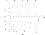
- Figure 4 illustrates the new foundation 10 in an unassembled flat condition.
- the new foundation 10 consists of only three parts: i) an elongated main wall plate 11, ii) a substantially square top plate 12, and iii) a substantially square bottom plate 13.
- the three plates 11, 12, 13 can be made of the same material, such as but not limited only to, for example, metal or metal alloy or composite or reinforced composite.
- the material of the main wall plate 11 can differ from the material of the top and bottom plates 12, 13.
- the material of each plate can differ from the material of either of the other two plates, meaning that each plate can be made of its own material differing from the other two materials.
- the main wall plate 11 comprises further three (-3-) weak links 40 which can be evenly arranged along the longitudinal direction of the main wall plate 11, the three weak links 40 being also perpendicular to the longitudinal direction of the main wall plate 11, so that four walls with equal areal and size can be distinguished (as shown in figures 3 and 4 ).
- the three weak links 40 can be arranged along the longitudinal direction of the main wall plate 11 in such a manner, so that, in the longitudinal direction of the main wall plate 11 and for example from one short side of the main wall plate 11 to the other short side of the main wall plate 11, the first wall will have the same areal and size as the third wall, and the second wall will have the same areal and size as the fourth wall.
- the weak links 40 can be constituted as holes in the main wall plate 11.
- the weak links 40 can be constituted as grooves in the main wall plate 11 so that the thickness of the weak links 40 is less than the thickness of the main wall plate 11.
- the grooves can then have a suitable shape, such as for example but not limited only to V-shape or U-shape.
- Each or at least one of the distinguished walls of the main wall plate 11 can have at least one hole 14 therein configured for reception of cable(s) and/or gravel therein.
- Each hole 14 can have a suitable shape, such as for example but not limited only to square or circular. In the embodiment shown on figures 3 and 4 each of the four equal walls is provided with two holes 14 which are square.
- first fastening means 20 On one short side or edge of the main wall plate 11 a first fastening means 20 can be arranged. On the other short side or edge of the main wall plate 11 a second fastening means 30 can be arranged.
- the first fastening means 20 is configured to cooperate with the second fastening means 30.
- the first fastening means 20 can be at least two holes
- the second fastening means 30 can be at least two collars, so that when the main flat wall plate 11 is folded along the three weak links 40 the collars 30 will go into the respective holes 20 and the fastening will be secured.
- each collar 30 could have a flange or flared end that is larger in diameter than the hole 20.
- each collar 30 can be provided with a slight taper, where the end that goes through the hole 20 is slightly narrower than the rest of the collar 30, so that this can help create a locking effect once the collar 30 is pushed through the hole 20.
- Locking mechanisms such as snap rings, retaining clips, or other types of locking devices that engage with the collar or hole to prevent unintended disassembly, can also be used.
- grooves, ridges or detents on the collar 30 can provide a mechanism that engages with the hole 20 or its edges, preventing the collar 30 from easily sliding out.
- the collar 30 can be designed with a slightly larger diameter than the hole 20 and using an interference fit (press fit) can create a tight connection that resists movement.
- a third fastening means 21 can be arranged on one long side or edge of the main wall plate 11 .
- a fourth fastening means 22 can be arranged on the other long side or edge of the main wall plate 11 .
- the third fastening means 21 can be configured to cooperate with a fastening means 31 of the bottom plate 13 arranged along the four sides or edges of the bottom plate 13.
- the fourth fastening means 22 can be configured to cooperate with a fastening means 32 of the top plate 12 arranged along the four sides or edges of the top plate 12.
- each of the third and fourth fastening means 21, 22 of the main wall plate 11 can be a set of several holes arranged near the two long sides or edges of the main wall plate 11.
- the fastening means 31, 32 of the top and bottom plates 12, 13, respectively, can be collars arranged on the four edges or sides of the top and bottom plates 12, 13.
- the fastening means 31, 32 of the top and bottom plates 12, 13 can be peripherally arranged holes near the four edges of each of the top and bottom plates 12, 13, and the third and fourth fastening means 21, 22 of the main wall plate 11 can be collars arranged on the two long sides or edges of the main wall plate 11 ( fig. 5 ).
- the last-mentioned fastening means 21, 22, 31, 32 can also be configured as previously described with regard to the fastening means 20, 30.
- the bottom plate 13 can comprise approximately in the middle thereof a hole 15, and the top plate 12 can comprise approximately in the middle thereof a hole 16.
- the shape of the holes 15, 16 can be as described with respect to the holes 14.
- the top plate 12 can also comprise at least one set of at least four circumferential or peripheral or edge holes 17 serving as attachment points for the charger post of the EV charging station.
- at least four circumferential or peripheral or edge holes 17 serving as attachment points for the charger post of the EV charging station.
- the flat-packed foundation 10 in said unassembled condition should be prepared for lowering into the trench, i.e. should be placed in said ready-for-embedment condition. This is made on site by an installer or mechanic, who is folding the main wall plate 11 along the three weak links 40, then puts the top and bottom plates 12, 13 at their respective places, and finally secures all of the fastening means, so that the foundation 10 gets its desired three-dimensional form.
- the necessary cable(s), power supply line(s) and/or communication cable(s) are installed.
- gravel is placed therein (i.e. into the foundation 10) through the holes 14, 15, 16. Additionally concrete can be poured between the foundation 10 and the walls of the trench. Alternatively, concrete can be poured into the foundation 10 as well as between the foundation 10 and the walls of the trench.
- the concrete is typically mixed using a specific ratio of cement, aggregates (such as sand and gravel), water and sometimes additives.
- the concrete mixture should be well-proportioned and mixed thoroughly to ensure uniformity.
- the design of the foundation 10 should be ensured that it extends below the frost line (if applicable) to prevent ground movement due to freezing and thawing cycles.
- the charger post is designed with corresponding attachment points that align with the set of holes 17, 18, 19 and together with the mounting elements (bolts, nuts, screws, other appropriate fasteners, etc.) a secure attachment of the charging post onto the embedded foundation 10 is provided. This connection ensures that the charger post, respectively the EV charging station, remains stable and upright.
- the charging cable(s), power supply line(s) and/or communication cable(s) can be connected to the appropriate terminals within the charger post after the step involving gravel and/or concrete and after the charger post is secured onto the embedded foundation 10.
- any excavated soil can be backfilled around the embedded foundation 10 to fill the hole or trench. If necessary, the area can be leveled and finished in order to create a clean and organized appearance.
- the embedded foundation 10 is serving as the backbone of the EV charging station, providing stability and safety for both the charging post and the vehicles using the charger.
Landscapes
- Engineering & Computer Science (AREA)
- Power Engineering (AREA)
- Transportation (AREA)
- Mechanical Engineering (AREA)
- Life Sciences & Earth Sciences (AREA)
- General Life Sciences & Earth Sciences (AREA)
- Mining & Mineral Resources (AREA)
- Paleontology (AREA)
- Civil Engineering (AREA)
- General Engineering & Computer Science (AREA)
- Structural Engineering (AREA)
- Charge And Discharge Circuits For Batteries Or The Like (AREA)
Applications Claiming Priority (1)
| Application Number | Priority Date | Filing Date | Title |
|---|---|---|---|
| NO20231262A NO20231262A1 (en) | 2023-11-21 | 2023-11-21 | Embedded foundation for electric vehicle charging station |
Publications (1)
| Publication Number | Publication Date |
|---|---|
| EP4563751A1 true EP4563751A1 (de) | 2025-06-04 |
Family
ID=93607761
Family Applications (1)
| Application Number | Title | Priority Date | Filing Date |
|---|---|---|---|
| EP24214259.4A Pending EP4563751A1 (de) | 2023-11-21 | 2024-11-20 | Eingebettetes fundament für ladestation für elektrofahrzeug |
Country Status (2)
| Country | Link |
|---|---|
| EP (1) | EP4563751A1 (de) |
| NO (1) | NO20231262A1 (de) |
Citations (2)
| Publication number | Priority date | Publication date | Assignee | Title |
|---|---|---|---|---|
| CN207633357U (zh) * | 2017-11-10 | 2018-07-20 | 武汉汉源既济电力有限公司 | 充电车站装配式基础 |
| GB2608373A (en) * | 2021-06-28 | 2023-01-04 | Nal Ltd | Modular electric vehicle charging foundation system |
Family Cites Families (1)
| Publication number | Priority date | Publication date | Assignee | Title |
|---|---|---|---|---|
| CN114714939A (zh) * | 2022-02-23 | 2022-07-08 | 江苏赛思柯机电设备科技有限公司 | 一种地下隐蔽式新能源充电桩 |
-
2023
- 2023-11-21 NO NO20231262A patent/NO20231262A1/en unknown
-
2024
- 2024-11-20 EP EP24214259.4A patent/EP4563751A1/de active Pending
Patent Citations (2)
| Publication number | Priority date | Publication date | Assignee | Title |
|---|---|---|---|---|
| CN207633357U (zh) * | 2017-11-10 | 2018-07-20 | 武汉汉源既济电力有限公司 | 充电车站装配式基础 |
| GB2608373A (en) * | 2021-06-28 | 2023-01-04 | Nal Ltd | Modular electric vehicle charging foundation system |
Also Published As
| Publication number | Publication date |
|---|---|
| NO348610B1 (en) | 2025-03-31 |
| NO20231262A1 (en) | 2025-03-31 |
Similar Documents
| Publication | Publication Date | Title |
|---|---|---|
| US9902600B2 (en) | Retaining wall system | |
| US6796098B2 (en) | Building block, system and method | |
| US20150101265A1 (en) | Prefabricated concrete pole base and adjustable connector | |
| WO2009110886A1 (en) | Tower foundation system | |
| US20130036678A1 (en) | Prefabricated concrete pole base and adjustable connector | |
| CN109403367A (zh) | 一种装配式箱变基础及其现场施工方法 | |
| WO2016049416A2 (en) | System and method for installation of arrays and support racks | |
| EP4563751A1 (de) | Eingebettetes fundament für ladestation für elektrofahrzeug | |
| US11280105B2 (en) | Prefabricated concrete pole base and method of installation | |
| US20230365014A1 (en) | Charging station foundation | |
| CN209353364U (zh) | 一种装配式箱变基础 | |
| CA2742262C (en) | Interlocking ballast block | |
| CN210151772U (zh) | 一种输电线路预制混凝土装配式基础 | |
| CN220789766U (zh) | 一种预制承台模板及具有其的施工构造 | |
| CN214061656U (zh) | 抗滑桩增设预应力锚索的组合抗滑结构 | |
| JP2016125270A (ja) | 擁壁用ブロック | |
| US20230143736A1 (en) | Universal, prefabricated foundation system for electric vehicle charging stations | |
| KR101803767B1 (ko) | 강관 파일의 두부 보강용 조립체 및 이를 포함하는 강관 파일 어셈블리 | |
| CN212114730U (zh) | 一种电缆沟装配式组合套件、装配式电缆沟 | |
| KR20200066827A (ko) | 지형에 따라 지지구조물의 지지가 용이한 근가장치 | |
| CN218813911U (zh) | 公路明挖隧道抗上浮结构 | |
| KR20190061260A (ko) | 상호결합을 위한 고정구를 구비한 좌굴 방지형 블록조립체 | |
| KR102374363B1 (ko) | 초연약지반 수직터파기용 가시설 월파일 및 이를 이용한 지반개량공법 | |
| JP2829717B2 (ja) | 重量物体の据付基礎の構築方法 | |
| JP3050729U (ja) | 耐震性貯水槽 |
Legal Events
| Date | Code | Title | Description |
|---|---|---|---|
| PUAI | Public reference made under article 153(3) epc to a published international application that has entered the european phase |
Free format text: ORIGINAL CODE: 0009012 |
|
| STAA | Information on the status of an ep patent application or granted ep patent |
Free format text: STATUS: THE APPLICATION HAS BEEN PUBLISHED |
|
| AK | Designated contracting states |
Kind code of ref document: A1 Designated state(s): AL AT BE BG CH CY CZ DE DK EE ES FI FR GB GR HR HU IE IS IT LI LT LU LV MC ME MK MT NL NO PL PT RO RS SE SI SK SM TR |
|
| STAA | Information on the status of an ep patent application or granted ep patent |
Free format text: STATUS: REQUEST FOR EXAMINATION WAS MADE |
|
| 17P | Request for examination filed |
Effective date: 20251203 |