EP4563014A1 - Aerosolerzeugungsartikel - Google Patents
Aerosolerzeugungsartikel Download PDFInfo
- Publication number
- EP4563014A1 EP4563014A1 EP24208015.8A EP24208015A EP4563014A1 EP 4563014 A1 EP4563014 A1 EP 4563014A1 EP 24208015 A EP24208015 A EP 24208015A EP 4563014 A1 EP4563014 A1 EP 4563014A1
- Authority
- EP
- European Patent Office
- Prior art keywords
- heat conduction
- section
- cooling section
- generating article
- aerosol generating
- Prior art date
- Legal status (The legal status is an assumption and is not a legal conclusion. Google has not performed a legal analysis and makes no representation as to the accuracy of the status listed.)
- Pending
Links
Images


Classifications
-
- A—HUMAN NECESSITIES
- A24—TOBACCO; CIGARS; CIGARETTES; SIMULATED SMOKING DEVICES; SMOKERS' REQUISITES
- A24D—CIGARS; CIGARETTES; TOBACCO SMOKE FILTERS; MOUTHPIECES OF CIGARS OR CIGARETTES; MANUFACTURE OF TOBACCO SMOKE FILTERS OR MOUTHPIECES
- A24D1/00—Cigars; Cigarettes
- A24D1/20—Cigarettes specially adapted for simulated smoking devices
-
- A—HUMAN NECESSITIES
- A24—TOBACCO; CIGARS; CIGARETTES; SIMULATED SMOKING DEVICES; SMOKERS' REQUISITES
- A24D—CIGARS; CIGARETTES; TOBACCO SMOKE FILTERS; MOUTHPIECES OF CIGARS OR CIGARETTES; MANUFACTURE OF TOBACCO SMOKE FILTERS OR MOUTHPIECES
- A24D3/00—Tobacco smoke filters, e.g. filter tips or filtering inserts; Filters specially adapted for simulated smoking devices; Mouthpieces of cigars or cigarettes
- A24D3/04—Tobacco smoke filters characterised by their shape or structure
-
- A—HUMAN NECESSITIES
- A24—TOBACCO; CIGARS; CIGARETTES; SIMULATED SMOKING DEVICES; SMOKERS' REQUISITES
- A24D—CIGARS; CIGARETTES; TOBACCO SMOKE FILTERS; MOUTHPIECES OF CIGARS OR CIGARETTES; MANUFACTURE OF TOBACCO SMOKE FILTERS OR MOUTHPIECES
- A24D3/00—Tobacco smoke filters, e.g. filter tips or filtering inserts; Filters specially adapted for simulated smoking devices; Mouthpieces of cigars or cigarettes
- A24D3/17—Filters specially adapted for simulated smoking devices
-
- A—HUMAN NECESSITIES
- A24—TOBACCO; CIGARS; CIGARETTES; SIMULATED SMOKING DEVICES; SMOKERS' REQUISITES
- A24F—SMOKERS' REQUISITES; MATCH BOXES; SIMULATED SMOKING DEVICES
- A24F40/00—Electrically operated smoking devices; Component parts thereof; Manufacture thereof; Maintenance or testing thereof; Charging means specially adapted therefor
- A24F40/20—Devices using solid inhalable precursors
Definitions
- the present application relates to the field of aerosol generating technology, and in particular, to an aerosol generating article.
- a Heat Not Burning (HNB) article is an aerosol generating article by heating an aerosol-generating substrate (a treated plant leaf product) without burning it.
- the Heat Not Burning article produce an aerosol by heating the aerosol-generating substrate at high temperature, but this temperature is insufficient to cause the aerosol-generating substrate to burn, so that the aerosol required by a user can be formed.
- a cooling section of the Heat Not Burning article can reduce the temperature of the aerosol, so that the aerosol flowing out of an inhalation port can reach a suitable temperature.
- the cooling section is generally a hot airflow condensing member, that is, it achieves the effect of reducing the temperature of the aerosol by means of solid heat transfer.
- the cooling sections in the related art have a low heat dissipation rate and a poor cooling effect, resulting in a poor user experience.
- the embodiments of the present application provide an aerosol generating article, comprising: a substrate section, a filter section and a cooling section having an airflow channel.
- the cooling section is disposed between the substrate section and the filter section.
- a first airflow path passing through at least the airflow channel is formed between the substrate section and the filter section.
- the cooling section comprises heat conduction members and a body having the airflow channel.
- the body has an outer surface and an inner surface located within the airflow channel, and at least one of the outer surface of the body and the inner surface of the body is provided with the heat conduction members.
- At least one of the outer surface of the body and the inner surface of the body is provided with a plurality of the heat conduction members at intervals in a circumferential direction, and each of the heat conduction members extends in an extending direction of the cooling section.
- the aerosol generating article comprises a tubular member having a cavity and air inlet holes.
- the substrate section, the cooling section and the filter section are sequentially disposed within the cavity.
- At least a part of the body is spaced apart from the tubular member to form a spacing space.
- the spacing space is in communication with the air inlet holes and the airflow channel, to form a second airflow path passing through the spacing space and the airflow channel, between the air inlet holes and the filter section.
- the outer surface of the body is provided with the heat conduction members located within the spacing space.
- each heat conduction member comprises a first heat conduction member disposed on the inner surface of the body.
- the first heat conduction member has a first arcuate surface and a second arcuate surface which are curved toward each other on both sides of the first heat conduction member.
- One side of each of the first arcuate surface and the second arcuate surface is located on the inner surface of the body, and the other sides of the first arcuate surface and the second arcuate surface have a communal edge away from the body.
- each heat conduction member comprises a first heat conduction member disposed on the inner surface of the body.
- the first heat conduction member is a cuboid; or the first heat conduction member has a first end disposed on the inner surface of the body and a second end opposite to the first end, the width of the second end gradually decreasing in a direction away from the first end.
- each heat conduction member comprises a second heat conduction member disposed on the outer surface of the body, the width of the second heat conduction member gradually decreasing in a direction away from the body.
- the cooling section is integrally formed by injection molding of an organic polymer material and at least one of graphite and a metal material.
- the metal material comprises at least one of iron, aluminum and copper; and/or the organic polymer material comprises at least one of fiber paper, silicone, a polylactic acid material, and a polyadipic acid material.
- the surface area of the heat conduction members is greater than or equal to 40% of the surface area of the cooling section and less than or equal to 80% of the surface area of the cooling section; and/or, the thermal conductivity of the cooling section is greater than or equal to 2700 W/(m K) and less than or equal to 5300 W/(m K).
- the embodiments of the present application provide an aerosol generating article, comprising: a substrate section, a filter section, and a cooling section having an airflow channel.
- the cooling section is disposed between the substrate section and the filter section, a first airflow path passing through at least the airflow channel is formed between the substrate section and the filter section, and at least one of an outer surface of a body of the cooling section and an inner surface of the body of the cooling section is provided with heat conduction members.
- the area of the outer surface of the cooling section in contact with the external environment can be significantly increased, so that the energy exchange between the cooling section and the external environment is sped up, thereby increasing the heat dissipation rate of the aerosol within the airflow channel by the cooling section.
- a better cooling effect can be achieved.
- the contact area between the cooling section and the aerosol within the airflow channel can be increased, so that the energy exchange between the cooling section and the aerosol can be sped up, so as to facilitate the cooling section to transfer the heat into the external environment.
- a better cooling effect can be achieved as well. It can be understood that, when both the outer surface and the inner surface of the body are provided with the heat conduction members, the surface area of the cooling section can be further increased, and thus the cooling effect of the cooling section can be further improved.
- substrate section 20. cooling section; 20a. airflow channel; 20b. spacing space; 21. heat conduction member; 211. first heat conduction member; 211a. first arcuate surface; 211b. second arcuate surface; 2111. first end; 2112. second end; 212. second heat conduction member; 22. body; 30. support section; 40. filter section; 50. tubular member; 50a. air inlet hole.
- orientation or position relationship of "an extending direction” is based on the orientation or position relationship shown in FIG. 2 .
- the terms of orientation are only for the purpose of facilitating the description of the present invention and simplifying the description, rather than indicating or implying that a device or element referred to must have a particular orientation or be constructed and operated in a particular orientation, and therefore cannot be understood as limiting the present application.
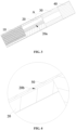
- An embodiment of the present application provides an aerosol generating article, as shown in FIGS. 2 and 3 , including a substrate section 10, a filter section 40, and a cooling section 20.
- the substrate section 10 is a region of the aerosol generating article in which an aerosol-generating substrate is mounted.
- the aerosol-generating substrate can produce an aerosol when heated in the substrate section 10, and the aerosol can flow with an external airflow as the external airflow passes through the substrate section 10 during an inhalation.
- the filter section 40 is configured to filter the aerosol and control the shape of the aerosol, so as to gather the aerosol, thereby reducing the phenomenon of dispersion of the aerosol. In addition, tiny particles generated during heating of the aerosol-generating substrate can be filtered out, thereby improving user experience.
- the cooling section 20 has an airflow channel 20a.
- the cooling section 20 is disposed between the substrate section 10 and the filter section 40.
- a first airflow path passing through at least the airflow channel 20a is formed between the substrate section 10 and the filter section 40.
- the airflow will pass through the substrate section 10, the airflow channel 20a and the filter section 40 sequentially.
- the cooling section 20 includes heat conduction members 21, and a body 22 having the airflow channel 20a.
- the body 22 has an outer surface and an inner surface opposite to the outer surface and located within the airflow channel 20a. At least one of the outer surface of the body 22 and the inner surface of the body 22 is provided with the heat conduction member 21.
- the aerosol generating article may be provided with another section, such as a support section 30, in addition to the substrate section 10, the cooling section 20 and the filter section 40.
- the support section 30 is disposed between the cooling section 20 and the filter section 40.
- the support section may allow the aerosol generating article to have a better support property, thereby making the structure more stable.
- the aerosol generating article includes a substrate section 10, a filter section 40, and a cooling section 20 having an airflow channel 20a.
- the cooling section 20 is disposed between the substrate section 10 and the filter section 40.
- a first airflow path passing through at least the airflow channel 20a is formed between the substrate section 10 and the filter section 40, and at least one of the outer surface of the body 22 and the inner surface of the body 22 of the cooling section 20 is provided with heat conduction members 21.
- the surface area of the cooling section 20 can be greatly increased.
- the area of the outer surface of the cooling section 20 in contact with the external environment can be significantly increased, so that the energy exchange between the cooling section 20 and the external environment speeds up, thereby increasing the heat dissipation rate of the aerosol within the airflow channel 20a by the cooling section 20.
- the contact area between the cooling section 20 and the aerosol within the airflow channel 20a can be increased, so that the energy exchange between the cooling section 20 and the aerosol can speed up, so as to facilitate the cooling section 20 to transfer the heat into the external environment.
- the heat dissipation effect of the cooling section 20 is related to the number, disposing manner and specific shape of the heat conduction members 21.
- the disposing manner and number of the heat conduction members 21 are not limited.
- the heat conduction member 21 is a heat sink fin.
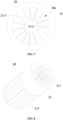
- At least one of the outer surface of the body 22 and the inner surface of the body 22 is provided with a plurality of heat conduction members 21 arranged at intervals in a circumferential direction.
- Each of the heat conduction members 21 extends in an extending direction of the cooling section 20.
- the outer surface of the body 22 is provided with a plurality of heat conduction members 21 arranged at intervals in the circumferential direction, or the inner surface of the body 22 is provided with a plurality of heat conduction members 21 arranged at intervals in the circumferential direction, or both of the outer surface and the inner surface of the body 22 are provided with a plurality of heat conduction members 21 arranged at intervals in the circumferential direction.
- the heat conduction members 21 is spaced apart from each other, which further increases the surface area of the cooling section 20, thereby further improving the heat dissipation effect of the cooling section 20.
- the heat conduction members 21 provided on the outer surface of the body 22 and the inner surface of the body 22 may be same or different in shape and structure.
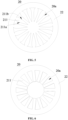
- each of the heat conduction members 21 includes a first heat conduction member 211 disposed on the inner surface of the body 22, and the first heat conduction member 211 is a cuboid.
- each first heat conduction member 211 has a first arcuate surface 211a and a second arcuate surface 211b which are curved toward each other on both sides of the first heat conduction member.
- One side of each of the first arcuate surface 211a and the second arcuate surface 211b is located on the inner surface of the body 22, and the other sides of the first arcuate surface 211a and the second arcuate surface 211b have a communal edge which is away from the body 22.
- Each first heat conduction member 211 is an arcuate heat conduction member.
- the surface area of the first heat conduction member 211 may be increased, so as to further improve the heat-conducting effect.
- the first arcuate surface 211a and the second arcuate surface 211b are curved toward each other on two sides, and the side edges of the first arcuate surface 211a and the second arcuate surface 211b on the side away from the body 22 overlap with each other, that is, a communal edge is formed. Therefore, the energy exchange between the first heat conduction members 211 and the aerosol can be facilitated.
- each first heat conduction member 211 has a first end 2111 disposed on the inner surface of the body 22, and a second end 2112 opposite to the first end 2111.
- the width of the second end 2112 gradually decreases in a direction away from the first end 2111.
- each first heat conduction member 211 that is connected to the inner surface of the body 22 is the first end 2111
- the end of each first heat conduction member 211 that is away from the body 22 is the second end 2112.
- the first end 2111 is not limited in shape, and it may be a structure having constant width, for example, a cuboid.
- the width of the cross section of the second end 2112 gradually decreases in the direction away from the first end 2111.
- the second end 2112 is a triangular prism structure.
- the second end 2112 in the form of the structure having a gradually decreasing width may facilitate the flowing of the aerosol within the airflow channel 20a.
- each of the heat conduction members 21 includes a second heat conduction member 212 disposed on the outer surface of the body 22, and the width of the second heat conduction member 212 gradually decreases in a direction away from the body 22. Therefore, the energy exchange between the second heat conduction member 212 and the external environment may be facilitated.
- the aerosol generating article includes a tubular member 50 having a cavity and air inlet holes 50a.
- the substrate section 10, the cooling section 20, and the filter section 40 are sequentially disposed within the cavity.
- At least a part of the body 22 is spaced apart from the tubular member 50 to form a spacing space 20b.
- the spacing space 20b is in communication with the air inlet holes 50a and the airflow channel 20a, to form a second airflow path passing through the spacing space 20b and the airflow channel 20a, between the air inlet holes 50a and the filter section 40.
- the air inlet holes 50a are in communication with the cavity.
- the aerosol generating article includes two airflow paths. By the arrangement of the two airflow paths, the air intake of the aerosol generating article may be increased, which may facilitate the user's inhalation.
- the air inlet holes 50a are airflow inlets for an external airflow flowing along the second airflow path.
- the specific position and number thereof are not limited.
- a plurality of air inlet holes 50a are arranged at intervals in a sidewall of the tubular member 50.
- the entire body 22 may be spaced apart from the tubular member 50, or only a part of the body 22 is spaced apart from the tubular member 50.
- a bottom end of the aerosol generating article also has airflow inlets for the external airflow flowing along the first airflow path.
- the outer surface of the body 22 is provided with the heat conduction members 21 located within the spacing space 20b.
- the heat conduction members 21 are disposed within the spacing space 20b.
- the inhalation after the energy exchange between the cooling section 20 and the aerosol, at least a part of the heat may be transferred into the spacing space 20b through the heat conduction members 21 disposed within the spacing space 20b. Therefore, the external airflow flowing into the second airflow path may be preheated, and thus a seepage phenomenon caused by the occurrence of condensation at the substrate section 10 and the cooling section 20 can be alleviated.
- the cooling section 20 is integrally formed by injection molding of an organic polymer material and at least one of graphite and a metal material.
- the material of the cooling section 20 may include graphite, a metal material, and an organic polymer material, or may include only graphite and the organic polymer material, or may include only the metal material and the organic polymer material.
- integrally formed by injection molding means that the organic polymer material is mixed with graphite and/or the metal material and then integrally molded by injection molding, extrusion and pressing. Therefore, the cooling section 20 may have a higher thermal conductivity, thereby allowing a better heat dissipation effect.
- the metal material may be determined according to the actual situation.
- the metal material includes at least one of iron, aluminum, and copper. That is, the metal material may include one or more of iron, aluminum, and copper.
- the organic polymer material includes at least one of fiber paper, silicone, a polylactic acid material (PLA), and a polyadipic acid material (PBAT). That is, the organic polymer material may be one or more of the above materials.
- the structure of the cooling section 20 itself has micro-pores.
- a "liquid film” may be formed on the inner surface of the body 22, which can adsorb macromolecules of the aerosol within the airflow channel 20a, so that the "graininess” felt by the user during the inhalation can be reduced, and thus the user's experience can be improved.
- the ratio of the surface area of the heat conduction members 21 to the surface area of the cooling section 20 should be within an appropriate range, and should not be too small, so as to avoid the poor heat dissipation effect of the cooling section 20.
- the ratio also should not be too large, so as to avoid the efficiency of the energy exchange between the cooling section 20 and the aerosol or the external environment from being affected by the crowded heat conduction members 21.
- the surface area of the heat conduction members 21 is greater than or equal to 40% of the surface area of the cooling section 20 and less than or equal to 80% of the surface area of the cooling section 20.
- the ratio may be 40%, 60%, 70% or 80%.
- the thermal conductivity of the cooling section 20 is greater than or equal to 2700 W/(m ⁇ K) and less than or equal to 5300 W/(m K).
- the cooling section 20 has a high thermal conductivity, and thus the heat of the aerosol can be rapidly transferred into the external environment.
- the thermal conductivity of the cooling section 20 may be 2700 W/(m K) or 5300 W/(m K).
- the surface area of the heat conduction members 21 is greater than or equal to 40% of the surface area of the cooling section 20 and less than or equal to than 70% of the surface area of the cooling section 20.
- the thermal conductivity of the cooling section 20 is greater than or equal to 3200 W/(m K) and less than or equal to 4500 W/(m K).
- the thermal conductivity of the cooling section may be 3200 W/(m ⁇ K), 4000 W/(m ⁇ K) or 4500 W/(m ⁇ K).
- the surface area of the heat conduction members 21 is greater than or equal to 60% of the surface area of the cooling section 20 and less than or equal to 80% of the surface area of the cooling section 20.
- the thermal conductivity of the cooling section 20 is greater than or equal to 3700W/(m ⁇ K) and less than or equal to 4700W/(m ⁇ K).
- the thermal conductivity of the cooling section may be 3700 W/(m ⁇ K), 4200 W/(m ⁇ K) or 4700 W/(m ⁇ K).
- the description with reference to the terms “in an embodiment,” “in some embodiments,” “in a specific embodiment,” “exemplary,” etc., means that the specific features, structures, materials, or characteristics described in connection with the embodiment or example are included in at least one embodiment or example of the embodiments of the present application.
- schematic representations of the above terms do not have to be directed to the same embodiment or example.
- the specific features, structures, materials, or characteristics described may be combined in any one or more embodiments or examples in a suitable manner.
- different embodiments or examples, and features of different embodiments or examples described in the present application may be combined by those skilled in the art without mutual contradiction.
Landscapes
- Cigarettes, Filters, And Manufacturing Of Filters (AREA)
- Cooling Or The Like Of Electrical Apparatus (AREA)
Applications Claiming Priority (1)
| Application Number | Priority Date | Filing Date | Title |
|---|---|---|---|
| CN202311388212.7A CN119867368A (zh) | 2023-10-24 | 2023-10-24 | 一种气溶胶生成制品 |
Publications (1)
| Publication Number | Publication Date |
|---|---|
| EP4563014A1 true EP4563014A1 (de) | 2025-06-04 |
Family
ID=93257915
Family Applications (1)
| Application Number | Title | Priority Date | Filing Date |
|---|---|---|---|
| EP24208015.8A Pending EP4563014A1 (de) | 2023-10-24 | 2024-10-22 | Aerosolerzeugungsartikel |
Country Status (3)
| Country | Link |
|---|---|
| EP (1) | EP4563014A1 (de) |
| JP (1) | JP7830596B2 (de) |
| CN (1) | CN119867368A (de) |
Citations (4)
| Publication number | Priority date | Publication date | Assignee | Title |
|---|---|---|---|---|
| CN109645552A (zh) * | 2018-12-25 | 2019-04-19 | 河南中烟工业有限责任公司 | 一种具有中空和沟槽结构的加热不燃烧卷烟 |
| JP2022116098A (ja) * | 2015-12-10 | 2022-08-09 | アール・ジエイ・レイノルズ・タバコ・カンパニー | 喫煙物品 |
| CN217564923U (zh) * | 2022-05-10 | 2022-10-14 | 乐智有限公司 | 烟弹 |
| WO2023099779A1 (en) * | 2021-12-02 | 2023-06-08 | Philip Morris Products S.A. | Aerosol-generating article having a grooved air channelling element |
Family Cites Families (2)
| Publication number | Priority date | Publication date | Assignee | Title |
|---|---|---|---|---|
| CN108095195B (zh) * | 2017-12-22 | 2020-11-27 | 安徽中烟工业有限责任公司 | 一种气雾产生物品 |
| CN213848738U (zh) * | 2020-07-27 | 2021-08-03 | 深圳市合元科技有限公司 | 气雾产生制品和气雾生成系统 |
-
2023
- 2023-10-24 CN CN202311388212.7A patent/CN119867368A/zh active Pending
-
2024
- 2024-10-17 JP JP2024181426A patent/JP7830596B2/ja active Active
- 2024-10-22 EP EP24208015.8A patent/EP4563014A1/de active Pending
Patent Citations (4)
| Publication number | Priority date | Publication date | Assignee | Title |
|---|---|---|---|---|
| JP2022116098A (ja) * | 2015-12-10 | 2022-08-09 | アール・ジエイ・レイノルズ・タバコ・カンパニー | 喫煙物品 |
| CN109645552A (zh) * | 2018-12-25 | 2019-04-19 | 河南中烟工业有限责任公司 | 一种具有中空和沟槽结构的加热不燃烧卷烟 |
| WO2023099779A1 (en) * | 2021-12-02 | 2023-06-08 | Philip Morris Products S.A. | Aerosol-generating article having a grooved air channelling element |
| CN217564923U (zh) * | 2022-05-10 | 2022-10-14 | 乐智有限公司 | 烟弹 |
Also Published As
| Publication number | Publication date |
|---|---|
| JP2025072317A (ja) | 2025-05-09 |
| JP7830596B2 (ja) | 2026-03-16 |
| CN119867368A (zh) | 2025-04-25 |
Similar Documents
| Publication | Publication Date | Title |
|---|---|---|
| US7896063B2 (en) | Heat exchanger structure for battery module | |
| CN117134018A (zh) | 换热板、电池包和车辆 | |
| JP6773790B2 (ja) | 温度制御システムを備える燃料電池及びセルの熱制御のための方法 | |
| CN107606977A (zh) | 热交换单体、热交换机芯和全热交换器 | |
| CN109638379A (zh) | 储能模组用逆流式双风道冷却系统 | |
| TW200925836A (en) | Heat dissipation module | |
| EP4563014A1 (de) | Aerosolerzeugungsartikel | |
| CN209558628U (zh) | 电控盒和空调器 | |
| CN208581445U (zh) | 导风装置及电子设备 | |
| CN205811011U (zh) | 一种双向流电池热管理系统 | |
| KR20160044130A (ko) | 히트 파이프를 이용한 온풍기 | |
| CN114400396B (zh) | 一种电池散热装置 | |
| US20250185777A1 (en) | Drying apparatus | |
| EP3240376B1 (de) | Schrank | |
| CN113950226A (zh) | 电子设备 | |
| CN209329094U (zh) | 一种电池散热组件及锂电池 | |
| CN203243651U (zh) | 散热器及采用该散热器的变频器 | |
| CN205607223U (zh) | 一种高效翅片板和采用该翅片板的空气预热器 | |
| CN114198155B (zh) | 一种冷却结构 | |
| CN213147489U (zh) | 一种热能回收换气装置 | |
| CN115101786A (zh) | 一种平板膜增湿单元及平板膜增湿器 | |
| WO2022037124A1 (zh) | 电暖器 | |
| CN104089505A (zh) | 热管散热器 | |
| CN219180620U (zh) | 换热板、电池包和车辆 | |
| CN219037079U (zh) | 一种暖风机 |
Legal Events
| Date | Code | Title | Description |
|---|---|---|---|
| PUAI | Public reference made under article 153(3) epc to a published international application that has entered the european phase |
Free format text: ORIGINAL CODE: 0009012 |
|
| STAA | Information on the status of an ep patent application or granted ep patent |
Free format text: STATUS: THE APPLICATION HAS BEEN PUBLISHED |
|
| AK | Designated contracting states |
Kind code of ref document: A1 Designated state(s): AL AT BE BG CH CY CZ DE DK EE ES FI FR GB GR HR HU IE IS IT LI LT LU LV MC ME MK MT NL NO PL PT RO RS SE SI SK SM TR |
|
| STAA | Information on the status of an ep patent application or granted ep patent |
Free format text: STATUS: REQUEST FOR EXAMINATION WAS MADE |
|
| 17P | Request for examination filed |
Effective date: 20251117 |