EP4560064A1 - Abgabevorrichtung, wäschebehandlungsvorrichtung und steuerungsverfahren dafür - Google Patents
Abgabevorrichtung, wäschebehandlungsvorrichtung und steuerungsverfahren dafür Download PDFInfo
- Publication number
- EP4560064A1 EP4560064A1 EP23854155.1A EP23854155A EP4560064A1 EP 4560064 A1 EP4560064 A1 EP 4560064A1 EP 23854155 A EP23854155 A EP 23854155A EP 4560064 A1 EP4560064 A1 EP 4560064A1
- Authority
- EP
- European Patent Office
- Prior art keywords
- dispensing
- water
- box
- dispensing box
- pipeline
- Prior art date
- Legal status (The legal status is an assumption and is not a legal conclusion. Google has not performed a legal analysis and makes no representation as to the accuracy of the status listed.)
- Pending
Links
Images


Classifications
-
- D—TEXTILES; PAPER
- D06—TREATMENT OF TEXTILES OR THE LIKE; LAUNDERING; FLEXIBLE MATERIALS NOT OTHERWISE PROVIDED FOR
- D06F—LAUNDERING, DRYING, IRONING, PRESSING OR FOLDING TEXTILE ARTICLES
- D06F39/00—Details of washing machines not specific to a single type of machines covered by groups D06F9/00 - D06F27/00
- D06F39/02—Devices for adding soap or other washing agents
- D06F39/022—Devices for adding soap or other washing agents in a liquid state
-
- D—TEXTILES; PAPER
- D06—TREATMENT OF TEXTILES OR THE LIKE; LAUNDERING; FLEXIBLE MATERIALS NOT OTHERWISE PROVIDED FOR
- D06F—LAUNDERING, DRYING, IRONING, PRESSING OR FOLDING TEXTILE ARTICLES
- D06F29/00—Combinations of a washing machine with other separate apparatus in a common frame or the like, e.g. with rinsing apparatus
-
- D—TEXTILES; PAPER
- D06—TREATMENT OF TEXTILES OR THE LIKE; LAUNDERING; FLEXIBLE MATERIALS NOT OTHERWISE PROVIDED FOR
- D06F—LAUNDERING, DRYING, IRONING, PRESSING OR FOLDING TEXTILE ARTICLES
- D06F31/00—Washing installations comprising an assembly of several washing machines or washing units, e.g. continuous flow assemblies
-
- D—TEXTILES; PAPER
- D06—TREATMENT OF TEXTILES OR THE LIKE; LAUNDERING; FLEXIBLE MATERIALS NOT OTHERWISE PROVIDED FOR
- D06F—LAUNDERING, DRYING, IRONING, PRESSING OR FOLDING TEXTILE ARTICLES
- D06F33/00—Control of operations performed in washing machines or washer-dryers
- D06F33/30—Control of washing machines characterised by the purpose or target of the control
- D06F33/43—Control of cleaning or disinfection of washing machine parts, e.g. of tubs
-
- D—TEXTILES; PAPER
- D06—TREATMENT OF TEXTILES OR THE LIKE; LAUNDERING; FLEXIBLE MATERIALS NOT OTHERWISE PROVIDED FOR
- D06F—LAUNDERING, DRYING, IRONING, PRESSING OR FOLDING TEXTILE ARTICLES
- D06F33/00—Control of operations performed in washing machines or washer-dryers
- D06F33/50—Control of washer-dryers characterised by the purpose or target of the control
- D06F33/69—Control of cleaning or disinfection of washer-dryer parts, e.g. of tubs
-
- D—TEXTILES; PAPER
- D06—TREATMENT OF TEXTILES OR THE LIKE; LAUNDERING; FLEXIBLE MATERIALS NOT OTHERWISE PROVIDED FOR
- D06F—LAUNDERING, DRYING, IRONING, PRESSING OR FOLDING TEXTILE ARTICLES
- D06F39/00—Details of washing machines not specific to a single type of machines covered by groups D06F9/00 - D06F27/00
- D06F39/02—Devices for adding soap or other washing agents
- D06F39/028—Arrangements for selectively supplying water to detergent compartments
-
- D—TEXTILES; PAPER
- D06—TREATMENT OF TEXTILES OR THE LIKE; LAUNDERING; FLEXIBLE MATERIALS NOT OTHERWISE PROVIDED FOR
- D06F—LAUNDERING, DRYING, IRONING, PRESSING OR FOLDING TEXTILE ARTICLES
- D06F2103/00—Parameters monitored or detected for the control of domestic laundry washing machines, washer-dryers or laundry dryers
- D06F2103/18—Washing liquid level
-
- D—TEXTILES; PAPER
- D06—TREATMENT OF TEXTILES OR THE LIKE; LAUNDERING; FLEXIBLE MATERIALS NOT OTHERWISE PROVIDED FOR
- D06F—LAUNDERING, DRYING, IRONING, PRESSING OR FOLDING TEXTILE ARTICLES
- D06F2103/00—Parameters monitored or detected for the control of domestic laundry washing machines, washer-dryers or laundry dryers
- D06F2103/38—Time, e.g. duration
-
- D—TEXTILES; PAPER
- D06—TREATMENT OF TEXTILES OR THE LIKE; LAUNDERING; FLEXIBLE MATERIALS NOT OTHERWISE PROVIDED FOR
- D06F—LAUNDERING, DRYING, IRONING, PRESSING OR FOLDING TEXTILE ARTICLES
- D06F2105/00—Systems or parameters controlled or affected by the control systems of washing machines, washer-dryers or laundry dryers
- D06F2105/02—Water supply
-
- D—TEXTILES; PAPER
- D06—TREATMENT OF TEXTILES OR THE LIKE; LAUNDERING; FLEXIBLE MATERIALS NOT OTHERWISE PROVIDED FOR
- D06F—LAUNDERING, DRYING, IRONING, PRESSING OR FOLDING TEXTILE ARTICLES
- D06F2105/00—Systems or parameters controlled or affected by the control systems of washing machines, washer-dryers or laundry dryers
- D06F2105/08—Draining of washing liquids
Definitions
- the present invention belongs to the technical field of household appliances, and in particular, relates to a dispensing device, a laundry treatment device and a control method thereof.
- the washing machine performs washing, rinsing and spin-drying operations to remove stains attached to clothes by using the interaction of detergent and water.
- a dryer as another representative laundry treatment device, is a home appliance for drying wet clothes, etc. Recently, home appliances having the combined functions of a washing machine and a dryer have been widely used.
- a multi-drum washing machine can meet the above needs and solve the problem of waste of energy, water and space.
- the existing drum washing machine comprises an upper water drum, a lower water drum and a dispensing component for dispensing detergent into the water drum
- the dispensing component comprises a first dispensing box and a second dispensing box
- liquid storage boxes can be push-pull arranged in the first dispensing box and the second dispensing box.
- the detergent in the second dispensing box is sucked into the first dispensing box by a suction pump, and the water inlet flow in the first dispensing box flushes the detergent into the upper water drum and/or the lower water drum. Since the second dispensing box is not connected to the water inlet pipeline, the detergent remaining in the second dispensing box due to pushing and pulling the liquid storage box cannot be flushed into the washing drum and fully utilized, thereby resulting in a waste of detergent.
- the technical problem to be solved by the present invention is to overcome the shortcomings of the prior art and provide a dispensing device and a laundry treatment device, which utilizes the inlet water flowing through the first dispensing box and the flushing pipeline to flush the second dispensing box, thereby achieving the purpose of avoiding residual detergent in the second dispensing box and reducing detergent waste.
- the present invention provides a dispensing device, comprising a first dispensing box and a second dispensing box.
- the first dispensing box is provided with a water inlet channel.
- the dispensing device further comprises a flushing pipeline, wherein a water inlet of the flushing pipeline is connected to a water outlet of the water inlet channel, and a water outlet of the flushing pipeline is connected to a water inlet of the second dispensing box.
- first dispensing box and the second dispensing box are arranged side by side on left and right.
- the water outlet of the water inlet channel is arranged on the first dispensing box and faces to the water inlet of the second dispensing box, and the flushing pipeline is arranged between the first dispensing box and the second dispensing box and extends horizontally between the first dispensing box and the second dispensing box.
- a recycling pipeline for recycling a mixed liquid obtained by flushing the second dispensing box is provided between the first dispensing box and the second dispensing box, a liquid inlet of the recycling pipeline is connected to a liquid outlet of the second dispensing box, and a liquid outlet of the recycling pipeline is connected to a liquid inlet of the first dispensing box, and the first dispensing box has a liquid outlet.
- a first dispensing cavity and a second dispensing cavity are provided in the first dispensing box; a first recycling pipeline corresponding to the first dispensing cavity and a second recycling pipeline corresponding to the second dispensing cavity are provided between the first dispensing box and the second dispensing box.
- the first dispensing cavity is provided with a first liquid outlet provided at a bottom of the first dispensing box, and the second dispensing cavity is provided with a second liquid outlet provided at a side of the first dispensing box.
- first recycling pipeline and the second recycling pipeline extend horizontally between the first dispensing box and the second dispensing box.
- the first recycling pipeline, the second recycling pipeline and the flushing pipeline are arranged at a same height, and the first recycling pipeline and the second recycling pipeline are respectively arranged on a front and rear sides of the flushing pipeline.
- a liquid storage box for storing detergent is provided inside the second dispensing box, a dispensing pipeline is provided between the first dispensing box and the second dispensing box.
- a liquid inlet of the dispensing pipeline is connected to a liquid outlet of the liquid storage box, and a liquid outlet of the dispensing pipeline is connected to the liquid inlet of the first dispensing box.
- a first liquid storage box and a second liquid storage box are arranged side by side in the second dispensing box, a first dispensing pipeline corresponding to the first liquid storage box and a second dispensing pipeline corresponding to the second liquid storage box are arranged between the first dispensing box and the second dispensing box. And a liquid outlet of the first dispensing pipeline and a liquid outlet of the second dispensing pipeline are both connected to the first dispensing cavity and the second dispensing cavity.
- first dispensing pipeline and the second dispensing pipeline extend horizontally between the first dispensing box and the second dispensing box, the first dispensing pipeline, the second dispensing pipeline and the flushing pipeline are arranged at a same height.
- the first dispensing pipeline and the second dispensing pipeline are arranged front to rear and are arranged between the flushing pipeline and the second recycling pipeline.
- a third liquid storage box and a fourth liquid storage box are arranged side by side in the first dispensing box, a third dispensing pipeline is arranged on the third liquid storage box, and a fourth dispensing pipeline is arranged on the fourth liquid storage box.
- a liquid outlet of the third dispensing pipeline and a liquid outlet of the fourth dispensing pipeline are both connected to the first dispensing cavity and the second dispensing cavity.
- the present invention also provides a laundry treatment device, comprising a housing, and an upper water drum and a lower water drum arranged in the housing, and also comprising a dispensing device provided by the above technical solution, wherein the dispensing device is arranged above the upper water drum, the liquid outlet of the second dispensing box is connected to the liquid inlet of the first dispensing box, and the liquid outlet of the first dispensing box is respectively connected to the upper water drum and the lower water drum.
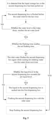
- the present invention also provides a control method for a laundry treatment device, using the laundry treatment device provided by the above technical solution, wherein the first dispensing box is connected to the second dispensing box via a flushing pipeline, the laundry treatment device has a flushing program, and when the flushing program is executed, the flushing pipeline is opened, and the second dispensing box is flushed by inlet water flowing through the first dispensing box and the flushing pipeline.
- a flushing time for flushing the second dispensing box by the inlet water reaches a set flushing time or a number of flushing times reaches a set flushing time, it is determined that there is no detergent residue in the second dispensing box.
- the laundry treatment device further comprises a water drum.
- the inlet water rinses the second dispensing box, and if the flushing time does not reach the set flushing time when the water level in the water drum reaches the set water level, the inlet water rinses the second dispensing box again when the next time inletting water into the water drum.
- the inlet water continues to flush the second dispensing box, and the water level in the water storage drum is higher than the set water level, a drain port of the water drum is opened to discharge part of the water in the water drum, and the inlet water continues to flush the second dispensing box.
- a liquid storage box for storing liquid detergent is pull-out provided in the second dispensing box. If it is detected that the liquid storage box in the second dispensing box has been pulled, then there is detergent residue in the second dispensing box, and the second dispensing box is rinsed before the last rinsing.
- the laundry treatment device is provided with an upper water drum and a lower water drum, and the inlet water after flushing the second dispensing box enters the upper water drum and the lower water drum, or the inlet water after flushing the second dispensing box selectively enters either the upper water drum or the lower water drum.
- the upper water drum prioritizes the water inlet procedure over the lower water drum, and the inlet water after flushing the second dispensing box enters the upper water drum first. If the water level in the upper water drum does not reach the set water level and the flushing time does not reach the set flushing time when the lower water drum executes the water inlet procedure, the inlet water after flushing the second dispensing box enters the lower water drum at the same time as it enters the upper water drum.
- the upper water drum prioritizes the water inlet procedure before the lower water drum, and the inlet water after flushing the second dispensing box enters the upper water drum first.
- the water level in the upper water drum reaches the set water level and the flushing time has not reached the set flushing time, it is determined whether the lower water drum executes the water inlet procedure; if it is executed, the inlet water after flushing the second dispensing box enters the lower water drum while waiting for the lower water drum to inlet water.
- the present invention has the following beneficial effects compared with the prior art: By utilizing the inflow water flowing through the first dispensing box and the flushing pipeline to flush the second dispensing box, residual detergent in the second dispensing box is avoided, thereby reducing the waste of detergent.
- the terms “installed”, “connected”, and “connected” should be understood in a broad sense, for example, it can be a fixed connection, a detachable connection, or an integral connection; it can be a mechanical connection or an electrical connection; it can be a direct connection or an indirect connection through an intermediate medium.
- installed e.g., it can be a fixed connection, a detachable connection, or an integral connection; it can be a mechanical connection or an electrical connection; it can be a direct connection or an indirect connection through an intermediate medium.
- the present invention provides a dispensing device, including a first dispensing box 1 and a second dispensing box 2.
- the first dispensing box 1 is provided with a water inlet channel and also includes a flushing pipeline 3.
- the water inlet of the flushing pipeline 3 is connected to the water outlet of the water inlet channel, and the water outlet is connected to the water inlet of the second dispensing box 2.
- the second dispensing box 2 is flushed by using the water flow flowing through the first dispensing box 1 and the flushing pipeline 3, thereby avoiding residual detergent in the second dispensing box 2 and reducing the waste of detergent.
- the types of the laundry treatment device include the following:
- the first type of laundry treatment device is a drum washing machine, which includes a housing 14, an outer drum, an inner drum rotatably arranged in the outer drum, and a dispensing assembly.
- the dispensing assembly includes a first dispensing box 1 and a second dispensing box 2; the inner drum is a hole-free inner drum, and the inner drum is used as a water storage drum when washing clothes independently. and the first dispensing box 1 and the second dispensing box 2 dispense detergent into the inner drum.
- the outer drum is a water storage drum, and the first dispensing box 1 and the second dispensing box 2 dispense detergent into the outer drum.
- the second type of laundry treatment device is a double-drum washing machine, which includes a housing 14, a first outer drum and a second outer drum arranged in the housing 14, a first inner drum arranged in the first outer drum, a second inner drum arranged in the second outer drum, and a dispensing component.
- the dispensing component includes a first dispensing box 1 and a second dispensing box 2; the first inner drum and the second inner drum are inner drums without holes, and the inner drums are used as water containing drums when washing clothes independently, and the first dispensing box 1 and the second dispensing box 2 dispense detergent into the first inner drum and the second inner drum.
- the first outer drum and the second outer drum are water containing drums, and the first dispensing box 1 and the second dispensing box 2 dispense detergent into the first outer drum and the second outer drum.
- the housing 14 can be a first housing 14 and a second housing 14 independent of each other, the first outer drum and the first inner drum are arranged in the first housing 14, and the second outer drum and the second inner drum are arranged in the second housing 14.
- the first dispensing box 1 and the second dispensing box 2 are arranged on the top portion of the housing 14 and above all the drums, the liquid outlet of the second dispensing box 2 is connected with the liquid inlet of the first dispensing box 1, and the liquid outlet of the first dispensing box 1 is respectively connected with the upper water drum 15 and the lower water drum 16; the first dispensing box 1 is connected with the external water inlet pipeline.
- the first dispensing box 1 is provided with a water inlet channel connected with the flushing pipeline 3, a water inlet channel for flushing the detergent in the first dispensing box 1 and for feeding water into the water drum, and each water inlet channel is connected with the external water inlet pipeline.
- the dispensing device includes not only the first dispensing box 1 and the second dispensing box 2, but also other dispensing boxes, and the type of detergent delivered by each dispensing box may be the same or different.
- the first dispensing box 1 comprises a box body and a box cover, wherein the box cover comprises an upper cover and a lower cover which are buckled with each other. And the upper cover and the lower cover are buckled with each other, so that a plurality of independent water inlet channels are formed inside the box cover.
- a liquid storage box for storing detergent is provided in the second dispensing box 2.
- the liquid storage box can be pushed and pulled in the second dispensing box 2.
- liquid will leak. If the leaked liquid is not treated for a long time, it will become dry, hard, moldy, etc. Therefore, the flushing pipeline 3 is used to flush the residual detergent in the second dispensing box 2.
- the detergent in the second dispensing box 2 When dispensing, the detergent in the second dispensing box 2 is sucked into the first dispensing box 1 and mixed with the detergent in the first dispensing box 1.
- the mixed liquid is flushed into the upper water drum 15 and/or the lower water drum 16 by the water flow entering from the first dispensing box 1.
- the water flowing out from the water inlet channel of the first dispensing box 1 enters the second dispensing box 2 through the flushing pipeline 3 to flush the detergent remaining in the second dispensing box 2.
- the mixed liquid obtained after flushing the second dispensing box 2 enters the upper water drum 15 and/or the lower water drum 16 through the first dispensing box 1.
- the first dispensing box 1 and the second dispensing box 2 are arranged side by side on the left and right, a water outlet of the water inlet channel is arranged on the first dispensing box 1 and faces to a water inlet of the second dispensing box 2.
- the flushing pipeline 3 is arranged between the first dispensing box 1 and the second dispensing box 2 and extends horizontally between the first dispensing box 1 and the second dispensing box 2.
- the first dispensing box 1 and the second dispensing box 2 are arranged at the top of the housing 14 and above all the drums.
- the first dispensing box 1 is arranged on the left side of the housing 14, and the second dispensing box 2 is arranged on the right side of the housing 14, the first dispensing box 1 and the second dispensing box 2 have the same shape and specification, and the first dispensing box 1 and the second dispensing box 2 are arranged side by side.
- the first dispensing box 1 and the second dispensing box 2 are arranged in this way to facilitate manual delivery of detergent and make full use of the space of the housing 14.
- a water inlet channel is provided on the top of the first dispensing box 1. Since the water outlet of the water inlet channel is arranged face to face with the water inlet of the second dispensing box 2, the flushing pipeline 3 is provided between the first dispensing box 1 and the second dispensing box 2, which can shorten the length of the flushing pipeline 3, which reduces the space occupied, and reduces the flushing time, thereby improving the flushing efficiency.
- a suction pump can be provided on the flushing pipeline 3; and the flushing pipeline 3 extends horizontally between the first dispensing box 1 and the second dispensing box 2 to avoid bending of the flushing pipeline 3, reduce obstruction to the water flow, and speed up the flow of water.
- a recycling pipeline for recovering the mixed liquid obtained by flushing the second dispensing box 2 is provided between the first dispensing box 1 and the second dispensing box 2.
- the liquid inlet of the recycling pipeline is connected to the liquid outlet of the second dispensing box 2, and the liquid outlet is connected to the liquid inlet of the first dispensing box 1, and the first dispensing box 1 has a liquid outlet.
- the water flow enters the second dispensing box 2 from the flushing pipeline 3 to flush the second dispensing box 2, and a mixed liquid of water and detergent is obtained after flushing.
- a recycling pipeline is provided between the first dispensing box 1 and the second dispensing box 2. The recycling pipeline delivers the mixed liquid from the second dispensing box 2 to the first dispensing box 1, and the mixed liquid then enters the water drum from the liquid outlet of the first dispensing box 1.
- the first dispensing box 1 is provided with a first dispensing cavity and a second dispensing cavity, a first recycling pipeline 4 corresponding to the first dispensing cavity and a second recycling pipeline 5 corresponding to the second dispensing cavity are provided between the first dispensing box 1 and the second dispensing box 2.
- the first dispensing cavity has a first liquid outlet 17 provided at the bottom of the first dispensing box 1, and the second dispensing cavity has a second liquid outlet 18 provided at the side of the first dispensing box 1.
- the first liquid outlet 17 of the first dispensing cavity is communicated with the upper water drum 15, and the second liquid outlet 18 of the second dispensing cavity is communicated with the lower water drum 16.
- the first recycling pipeline 4 delivers the mixed liquid into the first dispensing cavity in the first dispensing box 1, and the mixed liquid then enters the upper water drum 15 from the first liquid outlet 17 of the first dispensing cavity
- the second recycling pipeline 5 delivers the mixed liquid into the second dispensing cavity in the first dispensing box 1, and the mixed liquid then enters the lower water drum 16 from the second liquid outlet 18 of the second dispensing cavity.
- the water level in the upper water drum 15 reaches the set water level
- the first recycling pipeline 4 continues to send the mixed liquid into the first dispensing cavity and the upper water drum 15
- the water level in the upper water drum 15 will exceed the set water level, resulting in the upper water drum 15 being unable to wash normally.
- the flushing time of the second dispensing box 2 has not reached the set time, and the second dispensing box 2 is not flushed sufficiently.
- the second recycling pipeline 5 can deliver the mixed liquid in the second dispensing box 2 into the second dispensing cavity and the lower water drum 16, so that the flushing time of the second dispensing box 2 can reach the set time, so that the residual detergent in the second dispensing box 2 can be fully cleaned.
- first recycling pipeline 4 and the second recycling pipeline 5 extend horizontally between the first dispensing box 1 and the second dispensing box 2, the first recycling pipeline 4, the second recycling pipeline 5 and the flushing pipeline 3 are arranged at the same height, and the first recycling pipeline 4 and the second recycling pipeline 5 are respectively arranged on the front and rear sides of the flushing pipeline 3.
- the first recycling pipeline 4 and the second recycling pipeline 5 extend horizontally, which can shorten the length of the pipeline, reduce the space occupied, avoid bending of the recycling pipeline, reduce obstruction to the water flow, speed up the flow of water, and improve the recovery efficiency.
- a suction pump can be set on the first recycling pipeline 4 and the second recycling pipeline 5.
- a liquid storage box for storing detergent is provided in the second dispensing box 2
- a dispensing pipeline is provided between the first dispensing box 1 and the second dispensing box 2
- the liquid inlet of the dispensing pipeline is connected to the liquid outlet of the liquid storage box
- the liquid outlet is connected to the liquid inlet of the first dispensing box 1.
- a liquid storage box for storing detergent is provided in the second dispensing box 2.
- the dispensing pipeline delivers the detergent in the liquid storage box into the first dispensing box 1, and the detergent is flushed into the water drum by the water flow in the first dispensing box 1.
- the second dispensing box 2 is provided with a first liquid storage box 6 and a second liquid storage box 7 arranged side by side on the left and right, and a first dispensing pipeline 8 corresponding to the first liquid storage box 6 and a second dispensing pipeline 9 corresponding to the second liquid storage box 7 are provided between the first dispensing box 1 and the second dispensing box 2.
- the liquid outlet of the first dispensing pipeline 8 and the liquid outlet of the second dispensing pipeline 9 are both connected to the first dispensing cavity and the second dispensing cavity.
- Two liquid storage boxes are provided in the second dispensing box 2. Different detergents or the same detergents can be stored in the two liquid storage boxes.
- the two liquid storage boxes are arranged side by side in the second dispensing box 2, so that the space in the second dispensing box 2 can be fully utilized.
- the first dispensing cavity is connected to a first water inlet channel
- the second dispensing cavity is connected to a second water inlet channel.
- the first water inlet channel introduces water into the first dispensing cavity to enter the upper water drum
- the second water inlet channel introduces water into the second dispensing cavity to enter the lower water drum 16.
- the first dispensing pipeline 8 delivers the detergent in the first liquid storage box 6 into the first dispensing cavity and the second dispensing cavity respectively
- the second dispensing pipeline 9 delivers the detergent in the second liquid storage box 7 into the first dispensing cavity and the second dispensing cavity respectively.
- the detergent in the first liquid storage box 6 and the detergent in the second liquid storage box 7 are mixed in the first dispensing cavity and in the second dispensing cavity.
- the water flow provided by the first water inlet flow channel flushes the mixed detergent in the first dispensing cavity into the upper water drum 15 through the first liquid outlet 17 of the first dispensing cavity
- the water flow provided by the second water inlet flow channel flushes the mixed detergent in the second dispensing cavity into the lower water drum 16 through the second liquid outlet 18 of the second dispensing cavity.
- first dispensing pipeline 8 and the second dispensing pipeline 9 extend horizontally between the first dispensing box 1 and the second dispensing box 2, the first dispensing pipeline 8.
- the second dispensing pipeline 9 and the flushing pipeline 3 are arranged at the same height.
- the first dispensing pipeline 8 and the second dispensing pipeline 9 are arranged front to back and are arranged between the flushing pipeline 3 and the second recycling pipeline 5.
- the first dispensing pipeline 8 and the second dispensing pipeline 9 extend horizontally, which can shorten the length of the pipeline, reduce the space occupied, avoid bending of the dispensing pipeline, reduce obstruction to the detergent, speed up the flow of the detergent, and improve the recovery efficiency.
- a suction pump can be set on the first dispensing pipeline 8 and the second dispensing pipeline 9.
- a detection component is provided in the second dispensing box 2, and the detection component includes a position detection device 19 for detecting whether the liquid storage box is pushed into the second dispensing box 2 and a liquid level detection device 20 for detecting whether the liquid level in the second dispensing box 2 reaches a set liquid level.
- the position detection device 19 detects whether the user has pushed or pulled the liquid storage box. If the liquid storage box has been pushed or pulled, the position detection device 19 will memorize it and rinse the second dispensing box 2 when it is not the last rinse.
- the probe of the position detection device 19 is embedded in the second dispensing box 2 from the top of the second dispensing box 2 and suspended in the second dispensing box 2.
- the probe can detect the second dispensing box 2; the position detection device 19 can be in various forms such as a micro switch and a reed switch.
- the probe of the liquid level detection device 20 is embedded in the second dispensing box 2 from the top of the second dispensing box 2 and is suspended in the second dispensing box 2.
- the liquid level detection device 20 can be in various forms such as a float switch.
- the liquid in the second dispensing box 2 exceeds the set water level when flushing the second dispensing box 2, the liquid level will submerge the steel probe. If the second dispensing box 2 continues to be flushed, the flushing water will overflow, which will damage the electrical components near the second dispensing box 2 and cause safety hazards.
- a third liquid storage box 10 and a fourth liquid storage box 11 are arranged side by side on the left and right inside the first dispensing box 1.
- a third dispensing pipeline is arranged on the third liquid storage box 10, and a fourth dispensing pipeline is arranged on the fourth liquid storage box 11.
- the liquid outlet of the third dispensing pipeline and the liquid outlet of the fourth dispensing pipeline are both connected to the first dispensing cavity and the second dispensing cavity.
- two liquid storage boxes are arranged in the first dispensing box 1, and different detergents or the same detergents can be stored in the two liquid storage boxes.
- the two liquid storage boxes are arranged side by side in the first dispensing box 1, so that the space in the first dispensing box 1 can be fully utilized.
- the third dispensing pipeline delivers the detergent in the third liquid storage box 10 into the first dispensing cavity and the second dispensing cavity respectively
- the fourth dispensing pipeline delivers the detergent in the fourth liquid storage box 11 into the first dispensing cavity and the second dispensing cavity respectively.
- the detergent in the third liquid storage box 10 and the detergent in the fourth liquid storage box 11 are mixed in the first dispensing cavity and in the second dispensing cavity.
- the water flow provided by the first water inlet flow channel flushes the mixed detergent in the first dispensing cavity into the upper water drum 15 through the first liquid outlet 17 of the first dispensing cavity
- the water flow provided by the second water inlet flow channel flushes the mixed detergent in the second dispensing cavity into the lower water drum 16 through the second liquid outlet 18 of the second dispensing cavity.
- Suction pumps are provided on both the third dispensing pipeline and the fourth dispensing pipeline.
- the first liquid outlet 17 of the first dispensing cavity is connected to the upper water drum 15 via the fifth dispensing pipeline 12
- the second liquid outlet 18 of the second dispensing cavity is connected to the lower water drum 16 via the sixth dispensing pipeline 13.
- the detergents in all the liquid storage boxes are sucked into the first dispensing cavity and the second dispensing cavity, all the detergents are mixed in the first dispensing cavity and mixed in the second dispensing cavity, and the water flow flushes the mixed detergents in the first dispensing cavity into the upper water drum 15 and the mixed detergents in the second dispensing cavity into the lower water drum 16.
- whether there is detergent residue in the second dispensing box 2 is determined by whether the flushing time reaches the set flushing time or whether the flushing times reach the set flushing times.
- the second dispensing box 2 is rinsed before the last rinse, and the rinse water and the residual detergent are flushed into the water drum at the same time.
- the reason for not rinsing in the last rinse is that the detergent will be flushed into the water drum, resulting in an unclean final rinse.
- the clothing treatment device further comprises a water drum, and when the first dispensing box 1 is supplied with water into the water drum, the inflowing water flow rinses the second dispensing box 2, and if the water level in the water drum reaches the set water level and the rinsing time does not reach the set rinsing time, the inflowing water flow rinses the second dispensing box 2 again when waiting for the next time water is supplied into the water drum.
- the water flow can enter the second dispensing box 2 from the first dispensing box 1 through the flushing pipeline 3 to flush the second dispensing box 2, so that the water flow can be fed into the water drum and flush the second dispensing box 2 when the water inlet waterway is fed with water.
- the second dispensing box 2 can be flushed until the water drum is filled with water for the second time, so that the sum of the flushing times before and after can reach the set flushing time.
- the incoming water flow continues to flush the second dispensing box 2
- the water level in the water drum is higher than the set water level
- the drain port of the water drum is opened, part of the water in the water drum is discharged, and the incoming water flow continues to flush the second dispensing box 2.
- the washing machine cannot operate normally.
- the washing machine alarm prompts that the clothes cannot be washed, and prompts the user to remove part of the water in the water drum, so that the water level in the water drum is lower than the set water level. Then, the incoming water flow continues to flush the second dispensing box 2. After the flushing time reaches the set flushing time, the washing machine is restarted to execute the washing program.
- the washing machine is provided with a timer, which is used to record the flushing time of the second dispensing box 2.
- the washing machine is provided with a controller, and the timer, the liquid level detection device 20 and the position detection device 19 are connected to the controller. The timer transmits the recorded flushing time to the controller.
- the liquid level detection device 20 detects that the liquid level in the second dispensing box 2 exceeds the set liquid level, the liquid in the second dispensing box 2 is sucked into the first dispensing box 1 to prevent the liquid in the second dispensing box 2 from overflowing due to excessive liquid, thereby damaging the electrical components near the second dispensing box 2 and causing safety hazards.
- the laundry treatment device has an upper water drum 15 and a lower water drum 16, and the incoming water flow after flushing the second dispensing box 2 enters the upper water drum 15 and the lower water drum 16, or the incoming water flow after flushing the second dispensing box 2 selectively enters the upper water drum 15 and the lower water drum 16.
- the upper water drum 15 prioritizes the water inlet procedure over the lower water drum 16, and the water flow after flushing the second dispensing box 2 first enters the upper water drum 15. If, when the lower water drum 16 executes the water inlet procedure, the water level in the upper water drum 15 does not reach the set water level, and the flushing time does not reach the set flushing time, then the water flow after flushing the second dispensing box 2 enters the upper water drum 15 and enters the lower water drum 16 at the same time.
- the upper water drum 15 prioritizes the water inlet procedure over the lower water drum 16.
- the water flow after flushing the second dispensing box 2 first enters the upper water drum 15.
- the flushing time has not reached the set flushing time, and it is determined whether the lower water drum 16 executes the water inlet procedure. If it is executed, the water flow after flushing the second dispensing box 2 enters the lower water drum 16 while waiting for the lower water drum 16 to inlet water.
- the present invention provides a control method for a laundry treatment device, wherein the laundry treatment device has a first dispensing box 1 and a second dispensing box 2, the first dispensing box 1 is connected to the second dispensing box 2 via a flushing pipeline 3.
- the laundry treatment device has a flushing program, and when the flushing program is executed, the flushing pipeline 3 is opened, and the second dispensing box 2 is flushed by the water flow flowing through the first dispensing box 1 and the flushing pipeline 3.
- the second dispensing box 2 is flushed by using the water flow flowing through the first dispensing box 1 and the flushing pipeline 3, thereby avoiding residual detergent in the second dispensing box 2 and reducing the waste of detergent.
- the laundry treatment device includes the following:
- the first type of laundry treatment device is a drum washing machine, which includes a housing 14, an outer drum, an inner drum rotatably arranged in the outer drum, and a dispensing assembly.
- the dispensing assembly includes a first dispensing box 1 and a second dispensing box 2;
- the inner drum is a hole-free inner drum, and the inner drum is used as a water storage drum when washing clothes independently, and the first dispensing box 1 and the second dispensing box 2 dispense detergent into the inner drum.
- the outer drum is a water storage drum, and the first dispensing box 1 and the second dispensing box 2 dispense detergent into the outer drum.
- the laundry treatment device is a double-drum washing machine, which includes a housing 14, a first outer drum and a second outer drum arranged in the housing 14, a first inner drum arranged in the first outer drum, a second inner drum arranged in the second outer drum, and a dispensing assembly.
- the dispensing assembly includes a first dispensing box 1 and a second dispensing box 2; the first inner drum and the second inner drum are inner drums without holes, and the inner drums are used as water drums when washing clothes independently, and the first dispensing box 1 and the second dispensing box 2 dispense detergent into the first inner drum and the second inner drum.
- the first outer drum and the second outer drum are water drums, and the first dispensing box 1 and the second dispensing box 2 dispense detergent into the first outer drum and the second outer drum.
- the housing 14 can be a first housing 14 and a second housing 14 independent of each other, the first outer drum and the first inner drum are arranged in the first housing 14, and the second outer drum and the second inner drum are arranged in the second housing 14.
- the first dispensing box 1 and the second dispensing box 2 are arranged on the top portion of the housing 14 and are located above all the drums.
- a liquid outlet of the second dispensing box 2 is connected with the liquid inlet of the first dispensing box 1, and the liquid outlet of the first dispensing box 1 is respectively connected with the upper water drum 15 and the lower water drum 16; the first dispensing box 1 is connected with the external water inlet pipeline.
- a liquid storage box for storing detergent is provided in the second dispensing box 2.
- the liquid storage box can be pushed and pulled in the second dispensing box 2. Liquid leakage may occur when the liquid storage box is pushed and pulled. If the leakage is not handled for a long time, the liquid may become dry, hard, moldy, etc. Therefore, the flushing pipeline 3 is used to flush the residual detergent in the second dispensing box 2.
- the detergent in the second dispensing box 2 When dispensing, the detergent in the second dispensing box 2 is sucked into the first dispensing box 1 and mixed with the detergent in the first dispensing box 1.
- the mixed liquid is flushed into the upper water drum 15 and/or the lower water drum 16 by the water flow entering from the first dispensing box 1.
- the water flowing out from the water inlet channel of the first dispensing box 1 enters the second dispensing box 2 through the flushing pipeline 3 to flush the detergent remaining in the second dispensing box 2.
- the mixed liquid obtained after flushing the second dispensing box 2 enters the upper water drum 15 and/or the lower water drum 16 through the first dispensing box 1.
- the arrows in the pipeline in Fig. 2 indicate the direction of fluid flow.
- the first dispensing box 1 and the second dispensing box 2 are arranged side by side on the left and right, the water outlet of the water inlet channel is arranged on the first dispensing box 1 and faces the water inlet of the second dispensing box 2, and the flushing pipeline 3 is arranged between the first dispensing box 1 and the second dispensing box 2 and extends horizontally between the first dispensing box 1 and the second dispensing box 2.
- the first dispensing box 1 and the second dispensing box 2 are arranged at the top portion of the housing 14 and above all the drums.
- the first dispensing box 1 is arranged on the left side of the housing 14, and the second dispensing box 2 is arranged on the right side of the housing 14.
- the first dispensing box 1 and the second dispensing box 2 have the same shape and specification, and the first dispensing box 1 and the second dispensing box 2 are arranged side by side.
- the first dispensing box 1 and the second dispensing box 2 are arranged in this way to facilitate manual delivery of detergent and make full use of the space of the housing 14.
- the first dispensing box 1 includes a box body and a box cover, and the box cover includes an upper cover and a lower cover that are buckled together.
- the upper cover and the lower cover are buckled together, so that a number of independent water inlet channels are formed inside the box cover; a water inlet channel is arranged on the top of the first dispensing box 1. Since the water outlet of the water inlet channel is arranged face to face with the water inlet of the second dispensing box 2, a flushing pipeline 3 is arranged between the first dispensing box 1 and the second dispensing box 2, which can shorten the length of the flushing pipeline 3, reduce the space occupied, and reduce the flushing time, thereby improving the flushing efficiency.
- a suction pump can be arranged on the flushing pipeline 3; and the flushing pipeline 3 extends horizontally between the first dispensing box 1 and the second dispensing box 2 to avoid bending of the flushing pipeline 3, reduce obstruction to the water flow, and speed up the flow of water.
- a recycling pipeline for recycling the mixed liquid obtained by flushing the second dispensing box 2 is provided between the first dispensing box 1 and the second dispensing box 2.
- the liquid inlet of the recycling pipeline is connected to the liquid outlet of the second dispensing box 2, and the liquid outlet is connected to the liquid inlet of the first dispensing box 1, and the first dispensing box 1 has a liquid outlet.
- the water flow enters the second dispensing box 2 from the flushing pipeline 3 to flush the second dispensing box 2, and a mixed liquid of water and detergent is obtained after flushing.
- a recycling pipeline is provided between the first dispensing box 1 and the second dispensing box 2. The recycling pipeline delivers the mixed liquid from the second dispensing box 2 to the first dispensing box 1, and the mixed liquid then enters the water drum from the liquid outlet of the first dispensing box 1.
- a first dispensing box 1 is provided with a first dispensing cavity and a second dispensing cavity, a first recycling pipeline 4 corresponding to the first dispensing cavity and a second recycling pipeline 5 corresponding to the second dispensing cavity are provided between the first dispensing box 1 and the second dispensing box 2.
- the first dispensing cavity has a first liquid outlet 17 provided at the bottom of the first dispensing box 1, and the second dispensing cavity has a second liquid outlet 18 provided at the side of the first dispensing box 1.
- the first liquid outlet 17 of the first dispensing cavity is communicated with the upper water drum 15, and the second liquid outlet 18 of the second dispensing cavity is communicated with the lower water drum 16.
- the first recycling pipeline 4 delivers the mixed liquid into the first dispensing cavity in the first dispensing box 1, and the mixed liquid then enters the upper water drum 15 from the first liquid outlet 17 of the first dispensing cavity
- the second recycling pipeline 5 delivers the mixed liquid into the second dispensing cavity in the first dispensing box 1, and the mixed liquid then enters the lower water drum 16 from the second liquid outlet 18 of the second dispensing cavity.
- the water level in the upper water drum 15 reaches the set water level
- the first recycling pipeline 4 continues to deliver the mixed liquid into the first dispensing cavity and the upper water drum 15
- the water level in the upper water drum 15 will exceed the set water level, resulting in the upper water drum 15 being unable to wash normally.
- the flushing time of the second dispensing box 2 has not reached the set flushing time, and the second dispensing box 2 is not flushed sufficiently.
- the second recycling pipeline 5 can send the mixed liquid in the second dispensing box 2 into the second dispensing cavity and the lower water drum 16, so that the flushing time of the second dispensing box 2 can reach the set flushing time, so that the residual detergent in the second dispensing box 2 can be fully cleaned.
- first recycling pipeline 4 and the second recycling pipeline 5 extend horizontally between the first dispensing box 1 and the second dispensing box 2, the first recycling pipeline 4, the second recycling pipeline 5 and the flushing pipeline 3 are arranged at the same height, and the first recycling pipeline 4 and the second recycling pipeline 5 are respectively arranged on the front and rear sides of the flushing pipeline 3.
- the first recycling pipeline 4 and the second recycling pipeline 5 extend horizontally, which can shorten the length of the pipeline, reduce the space occupied, avoid bending of the recycling pipeline, reduce obstruction to the water flow, speed up the flow of water, and improve the recovery efficiency.
- a suction pump can be set on the first recycling pipeline 4 and the second recycling pipeline 5.
- a liquid storage box for storing detergent is provided in the second dispensing box 2
- a dispensing pipeline is provided between the first dispensing box 1 and the second dispensing box 2
- the liquid inlet of the dispensing pipeline is connected to the liquid outlet of the liquid storage box, and the liquid outlet is connected to the liquid inlet of the first dispensing box 1.
- a liquid storage box for storing detergent is provided in the second dispensing box 2.
- the dispensing pipeline delivers the detergent in the liquid storage box into the first dispensing box 1, and the detergent is flushed into the water drum by the water flow in the first dispensing box 1.
- a first liquid storage box 6 and a second liquid storage box 7 are arranged side by side on the left and right in the second dispensing box 2, and a first dispensing pipeline 8 corresponding to the first liquid storage box 6 and a second dispensing pipeline 9 corresponding to the second liquid storage box 7 are provided between the first dispensing box 1 and the second dispensing box 2.
- the liquid outlet of the first dispensing pipeline 8 and the liquid outlet of the second dispensing pipeline 9 are both connected to the first dispensing cavity and the second dispensing cavity.
- Two liquid storage boxes are provided in the second dispensing box 2. Different detergents or the same detergents can be stored in the two liquid storage boxes.
- the two liquid storage boxes are arranged side by side in the second dispensing box 2, so that the space in the second dispensing box 2 can be fully utilized.
- the first dispensing cavity is connected to a first water inlet channel
- the second dispensing cavity is connected to a second water inlet channel.
- the first water inlet channel introduces water into the first dispensing cavity to enter the upper water drum
- the second water inlet channel introduces water into the second dispensing cavity to enter the lower water drum 16.
- the first dispensing pipeline 8 delivers the detergent in the first liquid storage box 6 into the first dispensing cavity and the second dispensing cavity respectively
- the second dispensing pipeline 9 delivers the detergent in the second liquid storage box 7 into the first dispensing cavity and the second dispensing cavity respectively.
- the detergent in the first liquid storage box 6 and the detergent in the second liquid storage box 7 are mixed in the first dispensing cavity and in the second dispensing cavity.
- the water flow provided by the first water inlet flow channel flushes the mixed detergent in the first dispensing cavity into the upper water drum 15 through the first liquid outlet 17 of the first dispensing cavity
- the water flow provided by the second water inlet flow channel flushes the mixed detergent in the second dispensing cavity into the lower water drum 16 through the second liquid outlet 18 of the second dispensing cavity.
- first dispensing pipeline 8 and the second dispensing pipeline 9 extend horizontally between the first dispensing box 1 and the second dispensing box 2.
- the first dispensing pipeline 8, the second dispensing pipeline 9 and the flushing pipeline 3 are arranged at the same height.
- the first dispensing pipeline 8 and the second dispensing pipeline 9 are arranged front to back and are arranged between the flushing pipeline 3 and the second recycling pipeline 5.
- the first dispensing pipeline 8 and the second dispensing pipeline 9 extend horizontally, which can shorten the length of the pipeline, reduce the space occupied, avoid bending of the dispensing pipeline, reduce obstruction to the detergent, speed up the flow of the detergent, and improve the recovery efficiency.
- a suction pump can be set on the first dispensing pipeline 8 and the second dispensing pipeline 9.
- a detection component is provided in the second dispensing box 2, and the detection component includes a position detection device 19 for detecting whether the liquid storage box is pushed into the second dispensing box 2 and a liquid level detection device 20 for detecting whether the liquid level in the second dispensing box 2 reaches a set liquid level.
- the position detection device 19 detects whether the user has pushed or pulled the liquid storage box. If the liquid storage box has been pushed or pulled, the position detection device 19 will memorize it and rinse the second dispensing box 2 when it is not the last rinse.
- the probe of the position detection device 19 is embedded in the second dispensing box 2 from the top of the second dispensing box 2 and suspended in the second dispensing box 2.
- the probe can detect the second dispensing box 2; the position detection device 19 can be in various forms such as a micro switch and a reed switch.
- the probe of the liquid level detection device 20 is embedded in the second dispensing box 2 from the top of the second dispensing box 2 and is suspended in the second dispensing box 2.
- the liquid level detection device 20 can be in various forms such as a float switch.
- the liquid in the second dispensing box 2 exceeds the set water level when flushing the second dispensing box 2, the liquid level will submerge the steel probe. If the second dispensing box 2 continues to be flushed, the flushing water will overflow, which will damage the electrical components near the second dispensing box 2 and cause safety hazards.
- a third liquid storage box 10 and a fourth liquid storage box 11 are arranged side by side on the left and right inside the first dispensing box 1.
- a third dispensing pipeline is arranged on the third liquid storage box 10, and a fourth dispensing pipeline is arranged on the fourth liquid storage box 11.
- the liquid outlet of the third dispensing pipeline and the liquid outlet of the fourth dispensing pipeline are both connected to the first dispensing cavity and the second dispensing cavity.
- two liquid storage boxes are arranged in the first dispensing box 1, and different detergents or the same detergents can be stored in the two liquid storage boxes.
- the two liquid storage boxes are arranged side by side in the first dispensing box 1, so that the space in the first dispensing box 1 can be fully utilized.
- the third dispensing pipeline delivers the detergent in the third liquid storage box 10 into the first dispensing cavity and the second dispensing cavity respectively
- the fourth dispensing pipeline delivers the detergent in the fourth liquid storage box 11 into the first dispensing cavity and the second dispensing cavity respectively.
- the detergent in the third liquid storage box 10 and the detergent in the fourth liquid storage box 11 are mixed in the first dispensing cavity and in the second dispensing cavity.
- the water flow provided by the first water inlet flow channel flushes the mixed detergent in the first dispensing cavity into the upper water drum 15 through the first liquid outlet 17 of the first dispensing cavity
- the water flow provided by the second water inlet flow channel flushes the mixed detergent in the second dispensing cavity into the lower water drum 16 through the second liquid outlet 18 of the second dispensing cavity.
- Suction pumps are provided on both the third dispensing pipeline and the fourth dispensing pipeline.
- the first liquid outlet 17 of the first dispensing cavity is connected to the upper water drum 15 via the fifth dispensing pipeline 12
- the second liquid outlet 18 of the second dispensing cavity is connected to the lower water drum 16 via the sixth dispensing pipeline 13.
- the detergents in all the liquid storage boxes are sucked into the first dispensing cavity and the second dispensing cavity, all the detergents are mixed in the first dispensing cavity and mixed in the second dispensing cavity.
- the water flow flushes the mixed detergents in the first dispensing cavity into the upper water drum 15 and the mixed detergents in the second dispensing cavity into the lower water drum 16.
- whether there is detergent residue in the second dispensing box 2 is determined by whether the flushing time reaches the set flushing time or whether the flushing times reach the set flushing times.
- the second dispensing box 2 is flushed before the water inlet for the last rinse, and the rinse water and the residual detergent are flushed into the water drum at the same time.
- the reason for not rinsing in the last rinse is that the detergent will be flushed into the water drum, resulting in an unclean final rinse.
- the clothes treatment device further comprises a water drum, and when the first dispensing box 1 is supplied with water into the water drum, the inflowing water flows to rinse the second dispensing box 2, and if the water level in the water drum reaches the set water level and the rinsing time does not reach the set rinsing time, the inflowing water flows to rinse the second dispensing box 2 again when waiting for the next time water flows into the water drum.
- the water flow can enter the second dispensing box 2 from the first dispensing box 1 through the flushing pipeline 3 to flush the second dispensing box 2, so that the water flow can be fed into the water drum and flush the second dispensing box 2 when the water inlet waterway is fed with water.
- the second dispensing box 2 can be flushed again when the water drum is feeding water for the second time, so that the sum of the flushing time before and after can reach the set flushing time.
- the incoming water flow continues to flush the second dispensing box 2.
- the drain port of the water drum is opened, part of the water in the water drum is discharged, and the incoming water flow continues to flush the second dispensing box 2.
- the water level in the water drum is higher than the set water level, and the washing machine cannot operate normally.
- the washing machine alarm prompts that the clothes cannot be washed, and prompts the user to remove part of the water in the water drum, so that the water level in the water drum is lower than the set water level, and the incoming water flow continues to flush the second dispensing box 2.
- the washing machine is restarted to execute the washing program.
- the washing machine is provided with a timer, which is used to record the flushing time of the second dispensing box 2.
- the washing machine is provided with a controller, and the timer, the liquid level detection device 20 and the position detection device 19 are connected to the controller. The timer transmits the detected flushing time to the controller.
- the liquid level detection device 20 detects that the liquid level in the second dispensing box 2 exceeds the set liquid level, the liquid in the second dispensing box 2 is sucked into the first dispensing box 1 to prevent the liquid in the second dispensing box 2 from overflowing due to excessive liquid, thereby damaging the electrical components near the second dispensing box 2 and causing safety hazards.
- the laundry treatment device has an upper water drum 15 and a lower water drum 16, and the incoming water flow after flushing the second dispensing box 2 enters the upper water drum 15 and the lower water drum 16, or the incoming water flow after flushing the second dispensing box 2 selectively enters the upper water drum 15 and the lower water drum 16.
- the upper water drum 15 prioritizes the water inlet procedure over the lower water drum 16, and the water flow after flushing the second dispensing box 2 enters the upper water drum 15.
- the water level in the upper water drum 15 does not reach the set water level, and the flushing time does not reach the set flushing time, then the water flow after flushing the second dispensing box 2 enters the upper water drum 15 and enters the lower water drum 16 at the same time.
- the upper water drum 15 prioritizes the water inlet procedure over the lower water drum 16.
- the water flow after flushing the second dispensing box 2 enters the upper water drum 15.
- the flushing time has not reached the set flushing time, and it is determined whether the lower water drum 16 executes the water inlet procedure. If it is executed, the water flow after flushing the second dispensing box 2 enters the lower water drum 16 while waiting for the lower water drum 16 to inlet water.
Landscapes
- Engineering & Computer Science (AREA)
- Textile Engineering (AREA)
- Detail Structures Of Washing Machines And Dryers (AREA)
- Control Of Washing Machine And Dryer (AREA)
Applications Claiming Priority (3)
| Application Number | Priority Date | Filing Date | Title |
|---|---|---|---|
| CN202210997497.3A CN115404669B (zh) | 2022-08-19 | 2022-08-19 | 一种投放装置及衣物处理装置 |
| CN202210997529.XA CN115404647A (zh) | 2022-08-19 | 2022-08-19 | 一种衣物处理装置的控制方法及衣物处理装置 |
| PCT/CN2023/106496 WO2024037250A1 (zh) | 2022-08-19 | 2023-07-10 | 一种投放装置、衣物处理装置及其控制方法 |
Publications (2)
| Publication Number | Publication Date |
|---|---|
| EP4560064A1 true EP4560064A1 (de) | 2025-05-28 |
| EP4560064A4 EP4560064A4 (de) | 2025-10-15 |
Family
ID=89940655
Family Applications (1)
| Application Number | Title | Priority Date | Filing Date |
|---|---|---|---|
| EP23854155.1A Pending EP4560064A4 (de) | 2022-08-19 | 2023-07-10 | Abgabevorrichtung, wäschebehandlungsvorrichtung und steuerungsverfahren dafür |
Country Status (5)
| Country | Link |
|---|---|
| US (1) | US20260210014A1 (de) |
| EP (1) | EP4560064A4 (de) |
| JP (1) | JP2025526932A (de) |
| AU (1) | AU2023327312B2 (de) |
| WO (1) | WO2024037250A1 (de) |
Family Cites Families (14)
| Publication number | Priority date | Publication date | Assignee | Title |
|---|---|---|---|---|
| US20100018259A1 (en) * | 2007-01-10 | 2010-01-28 | Seong Hae Jeong | Multiple laundry treating machine |
| KR101302125B1 (ko) * | 2007-03-20 | 2013-08-30 | 엘지전자 주식회사 | 세탁기 |
| KR20150072169A (ko) * | 2013-12-19 | 2015-06-29 | 삼성전자주식회사 | 세탁기 |
| JP2017121393A (ja) * | 2016-01-08 | 2017-07-13 | パナソニックIpマネジメント株式会社 | ドラム式洗濯機 |
| WO2018117526A1 (en) * | 2016-12-23 | 2018-06-28 | Samsung Electronics Co., Ltd. | Washing machine |
| WO2018128234A1 (en) * | 2017-01-03 | 2018-07-12 | Lg Electronics Inc. | Laundry treating apparatus |
| WO2019242546A1 (zh) * | 2018-06-21 | 2019-12-26 | 青岛海尔滚筒洗衣机有限公司 | 一种自动投放装置及控制方法及多滚筒洗衣机 |
| CN110699927B (zh) * | 2018-07-09 | 2023-06-13 | 青岛海尔洗涤电器有限公司 | 一种添加剂自动投放装置及方法及洗衣机 |
| CN113073448B (zh) * | 2020-01-06 | 2024-06-14 | 青岛海尔洗衣机有限公司 | 一种洗衣机投放装置、洗衣机及其控制方法 |
| JP2021126269A (ja) * | 2020-02-13 | 2021-09-02 | パナソニックIpマネジメント株式会社 | 洗濯機 |
| WO2022071176A1 (ja) * | 2020-10-02 | 2022-04-07 | パナソニックIpマネジメント株式会社 | 洗濯機 |
| CN114197170B (zh) * | 2021-12-30 | 2024-06-04 | Tcl家用电器(合肥)有限公司 | 自动投放组件及其控制方法和洗衣机 |
| CN115404669B (zh) * | 2022-08-19 | 2025-03-18 | 青岛海尔洗涤电器有限公司 | 一种投放装置及衣物处理装置 |
| CN115404647A (zh) * | 2022-08-19 | 2022-11-29 | 青岛海尔洗涤电器有限公司 | 一种衣物处理装置的控制方法及衣物处理装置 |
-
2023
- 2023-07-10 AU AU2023327312A patent/AU2023327312B2/en active Active
- 2023-07-10 WO PCT/CN2023/106496 patent/WO2024037250A1/zh not_active Ceased
- 2023-07-10 US US19/104,544 patent/US20260210014A1/en active Pending
- 2023-07-10 JP JP2025509073A patent/JP2025526932A/ja active Pending
- 2023-07-10 EP EP23854155.1A patent/EP4560064A4/de active Pending
Also Published As
| Publication number | Publication date |
|---|---|
| WO2024037250A1 (zh) | 2024-02-22 |
| AU2023327312A1 (en) | 2025-03-20 |
| AU2023327312B2 (en) | 2026-07-30 |
| JP2025526932A (ja) | 2025-08-15 |
| US20260210014A1 (en) | 2026-07-23 |
| EP4560064A4 (de) | 2025-10-15 |
Similar Documents
| Publication | Publication Date | Title |
|---|---|---|
| CN202193989U (zh) | 洗衣机 | |
| KR20080089088A (ko) | 세탁기 | |
| CN106381636A (zh) | 可以进行循环洗涤、漂洗和脱水的洗衣机及其控制方法 | |
| CN101498087A (zh) | 洗衣机 | |
| WO2020181829A1 (zh) | 注水控制方法、装置和衣物处理装置 | |
| CN114182480B (zh) | 洗涤装置的消泡方法、洗涤装置、存储介质和电子装置 | |
| CN115404669B (zh) | 一种投放装置及衣物处理装置 | |
| CN103443347A (zh) | 操作洗衣机或洗衣干衣机的方法及对应的洗衣机或洗衣干衣机 | |
| CN114369930A (zh) | 洗衣机 | |
| CN114197170A (zh) | 自动投放组件及其控制方法和洗衣机 | |
| CN101260605A (zh) | 洗衣机及其工作控制方法 | |
| WO2024027744A1 (zh) | 一种洗涤设备的控制方法及洗涤设备 | |
| CN115404647A (zh) | 一种衣物处理装置的控制方法及衣物处理装置 | |
| AU2023327312A1 (en) | Dispensing device, laundry treatment device and control method therefor | |
| CN111379117B (zh) | 一种多筒洗衣机及其控制方法 | |
| CN110485106B (zh) | 洗烘一体机 | |
| CN118727351A (zh) | 清洁一体机 | |
| CN214882401U (zh) | 洗衣机 | |
| CN212357686U (zh) | 一种多筒洗衣机 | |
| CN109629182B (zh) | 半自动投放系统及其控制方法 | |
| CN110552149A (zh) | 洗烘一体机 | |
| WO2022028065A1 (zh) | 洗衣机 | |
| CN220486063U (zh) | 清洁一体机 | |
| CN101864658B (zh) | 洗衣机及其工作控制方法 | |
| CN118121118A (zh) | 清洁设备 |
Legal Events
| Date | Code | Title | Description |
|---|---|---|---|
| STAA | Information on the status of an ep patent application or granted ep patent |
Free format text: STATUS: THE INTERNATIONAL PUBLICATION HAS BEEN MADE |
|
| PUAI | Public reference made under article 153(3) epc to a published international application that has entered the european phase |
Free format text: ORIGINAL CODE: 0009012 |
|
| STAA | Information on the status of an ep patent application or granted ep patent |
Free format text: STATUS: REQUEST FOR EXAMINATION WAS MADE |
|
| 17P | Request for examination filed |
Effective date: 20250221 |
|
| AK | Designated contracting states |
Kind code of ref document: A1 Designated state(s): AL AT BE BG CH CY CZ DE DK EE ES FI FR GB GR HR HU IE IS IT LI LT LU LV MC ME MK MT NL NO PL PT RO RS SE SI SK SM TR |
|
| REG | Reference to a national code |
Ref country code: DE Ref legal event code: R079 Free format text: PREVIOUS MAIN CLASS: D06F0039020000 Ipc: D06F0029000000 |
|
| A4 | Supplementary search report drawn up and despatched |
Effective date: 20250911 |
|
| RIC1 | Information provided on ipc code assigned before grant |
Ipc: D06F 29/00 20060101AFI20250905BHEP Ipc: D06F 39/02 20060101ALI20250905BHEP Ipc: D06F 33/43 20200101ALI20250905BHEP Ipc: D06F 33/69 20200101ALI20250905BHEP Ipc: D06F 103/00 20200101ALN20250905BHEP Ipc: D06F 103/18 20200101ALN20250905BHEP Ipc: D06F 105/02 20200101ALN20250905BHEP Ipc: D06F 105/08 20200101ALN20250905BHEP |
|
| DAV | Request for validation of the european patent (deleted) | ||
| DAX | Request for extension of the european patent (deleted) |