EP4559641A1 - Messer mit einziehbarer klinge - Google Patents
Messer mit einziehbarer klinge Download PDFInfo
- Publication number
- EP4559641A1 EP4559641A1 EP23307017.6A EP23307017A EP4559641A1 EP 4559641 A1 EP4559641 A1 EP 4559641A1 EP 23307017 A EP23307017 A EP 23307017A EP 4559641 A1 EP4559641 A1 EP 4559641A1
- Authority
- EP
- European Patent Office
- Prior art keywords
- blade
- knife
- blade holder
- arm
- holder
- Prior art date
- Legal status (The legal status is an assumption and is not a legal conclusion. Google has not performed a legal analysis and makes no representation as to the accuracy of the status listed.)
- Pending
Links
Images



Classifications
-
- B—PERFORMING OPERATIONS; TRANSPORTING
- B26—HAND CUTTING TOOLS; CUTTING; SEVERING
- B26B—HAND-HELD CUTTING TOOLS NOT OTHERWISE PROVIDED FOR
- B26B5/00—Hand knives with one or more detachable blades
- B26B5/001—Hand knives with one or more detachable blades with blades being slid out of handle immediately prior to use
Definitions
- the invention relates to the field of retractable blade knives of the type known by the English term "cutter” used in particular for cutting cardboard or carpets.
- Knives with blades that retract longitudinally into a knife body under the action of a sliding pusher on the back of the knife are known.
- changing the blade is generally a delicate operation that requires, for example, the disassembly of a cheek from the knife body.
- the knife may comprise a second arm provided with a free end, receiving said spring device, this free end being kept away from the blade holder by said spring device, the blocker being in said blade blocking position, said free end being provided with said support part.
- Said pivot axis advantageously comprises two pins received in housings of the blade holder and around which the blocker can pivot.
- the first arm may extend from said pivot axis to a front portion of the blade holder from which the blade protrudes.
- the second arm may extend from said pivot axis to a rear portion of the blade holder opposite a front portion of the blade holder from which the blade protrudes.
- the knife may include a blade holder operating bracket mounted to slide on the knife body.
- the blade holder and the operating bracket may include additional means of securing movement in the direction of entry and exit of the blade.
- the operating bracket can slide on the body by means of a groove and tongue device.
- the operating bracket can hide said pusher in a blade retracted position and leave said pusher visible in a blade extended position.
- the blade holder can be returned to the blade retracted position by a return spring.
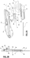
- the knife comprises two lateral half-shells 1a, 1b which receive a blade holder 2 movable along a longitudinal axis A.
- the blade holder 2 carries a blade 4 which can exit longitudinally from a first end 10 of the knife along the axis A.
- the two assembled half-shells 1a, 1b form a knife handle provided on its upper part with a stirrup 6 for operating the blade holder.
- the blade holder is pushed into the blade exit position by the stirrup 6 and is returned to a blade retract position in the body of the knife by a return spring 7, a rear end of which is fixed on a first tenon 13 of one of the half-shells and the front end of which is fixed on a second tenon 24 of the blade holder shown in Figure 2A .
- the blade is inserted into the blade holder through a front of this blade holder located on the side of the first end 10 of the knife.
- a blade blocker 3 is mounted on the blade holder.
- This blade blocker comprises, according to a first embodiment, the subject of the figures 1 to 3 a pivot axis B, transverse to the direction of movement of the blade holder between the retracted position of the blade in the knife and the extended position of the blade.
- the pivot axis comprises two pins 31 received in housings 21 of the blade holder which allows the pivoting of the blade blocker around the pivot axis.
- the blade blocker as shown further comprises, according to this first embodiment, a first arm 3a, comprising a free end provided with a pin 33 for locking the blade inserted into a hole 41 in the blade and a second arm 3b provided with a free end held apart from the blade holder by a spring element 5, the blocker being in said blade locking position, said free end being provided with a bearing part 32 on which a pusher 11 is capable of pushing in a pushing direction P1 causing the blocker to tilt, which releases the pin 33 from the hole 41 and thus allows the blade to be removed from the blade holder.
- the first and second arms are on opposite sides relative to the pivot axis B as seen in Figure 2B
- the pusher 11 is on the side opposite the pin 33 relative to a plane of the blocker comprising the first arm and the axis B.
- the spring device 5 presses on the face of the second arm 3b opposite that on which the pusher 11 is applied and is partly received in a housing of the blade holder 2.
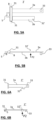
- the second arm can also be arranged on the same side as the first arm relative to the pivot axis, the second arm is, in this example, parallel to the first arm and the thrust P2 on a support part 32' is made on the same side as the pin on the first arm.
- the second arm can even be omitted and a 32" support part is made on a part of the first arm.
- the P2 thrust is made on the side where the pawn is located on the first arm.
- the pusher element 11 associated with the body and positioned opposite said support part 32 when the blade holder is in the blade exit position is configured so that pressing on the pusher element pushes said second arm of said blocker with a thrust P1 against said spring 5 so as to tilt the blocker around said axis B and release the blade 4 by releasing the pin 33 at the end of the first arm from the hole 41 in the blade.
- the push element 11 is made from a spring tab made in a half-shell 1a.
- This push element can also be a mobile element attached to the knife body.
- the knife according to the example comprises a stirrup 6 for operating the blade holder mounted to slide on the knife body 1a, 1b.
- the blade holder 2 and the stirrup 6 comprise complementary means 23, 62, 63 for securing in movement in the direction of entry and exit of the blade.
- these means comprise a first tab 23 protruding from an upper part of the blade holder 2 and two second tabs 62, 63 inside the pusher 6 seen in section at Figure 3 , these second tabs being positioned on either side of the first tab in a longitudinal direction of advance and retraction of the pusher to drive the blade holder in the direction of exit of the blade and so that the blade holder returned by the return spring 7 drives the pusher in the direction of retraction of the blade.
- the stirrup 6 slides on the body by means of a groove-tongue device 12, 61, the stirrup here comprising two tongues 61 which snap into grooves 12 of the body of the knife on each side, said body.
- the stirrup 6 hides the pusher 11 and, to allow the blade to be removed when it is extended, the stirrup leaves said pusher 11 visible in the forward position.
- This system provides safe handling because the operator must push the pusher with one hand and press the pusher with the other to extract the blade.
- the invention can be applied in particular to knives known by the term "cutter" from the English language.
- the pusher and the support part can be positioned differently, for example the support part can extend towards a lower part of the knife, the pusher comprising a finger entering the body of the knife and being actuated from below the knife.
Landscapes
- Life Sciences & Earth Sciences (AREA)
- Forests & Forestry (AREA)
- Engineering & Computer Science (AREA)
- Mechanical Engineering (AREA)
- Knives (AREA)
Priority Applications (1)
| Application Number | Priority Date | Filing Date | Title |
|---|---|---|---|
| EP23307017.6A EP4559641A1 (de) | 2023-11-21 | 2023-11-21 | Messer mit einziehbarer klinge |
Applications Claiming Priority (1)
| Application Number | Priority Date | Filing Date | Title |
|---|---|---|---|
| EP23307017.6A EP4559641A1 (de) | 2023-11-21 | 2023-11-21 | Messer mit einziehbarer klinge |
Publications (1)
| Publication Number | Publication Date |
|---|---|
| EP4559641A1 true EP4559641A1 (de) | 2025-05-28 |
Family
ID=89119157
Family Applications (1)
| Application Number | Title | Priority Date | Filing Date |
|---|---|---|---|
| EP23307017.6A Pending EP4559641A1 (de) | 2023-11-21 | 2023-11-21 | Messer mit einziehbarer klinge |
Country Status (1)
| Country | Link |
|---|---|
| EP (1) | EP4559641A1 (de) |
Citations (3)
| Publication number | Priority date | Publication date | Assignee | Title |
|---|---|---|---|---|
| US20160039100A1 (en) * | 2012-06-28 | 2016-02-11 | Hangzhou Great Star Tools Co., Ltd. | Utility Knife |
| US20170129112A1 (en) * | 2015-11-05 | 2017-05-11 | Stanley Black & Decker, Inc. | Utility knife with skewed pivotal blade lock |
| US20190176349A1 (en) * | 2009-03-04 | 2019-06-13 | Stanley Black & Decker, Inc. | Utility knife |
-
2023
- 2023-11-21 EP EP23307017.6A patent/EP4559641A1/de active Pending
Patent Citations (3)
| Publication number | Priority date | Publication date | Assignee | Title |
|---|---|---|---|---|
| US20190176349A1 (en) * | 2009-03-04 | 2019-06-13 | Stanley Black & Decker, Inc. | Utility knife |
| US20160039100A1 (en) * | 2012-06-28 | 2016-02-11 | Hangzhou Great Star Tools Co., Ltd. | Utility Knife |
| US20170129112A1 (en) * | 2015-11-05 | 2017-05-11 | Stanley Black & Decker, Inc. | Utility knife with skewed pivotal blade lock |
Similar Documents
| Publication | Publication Date | Title |
|---|---|---|
| EP0634252B1 (de) | Taschenmesser mit einer verriegelbaren Klinge und einer Druckknopfentriegelungsvorrichtung | |
| EP1177865B1 (de) | Schneider mit automatisch einziehbarer Klinge | |
| FR2848138A1 (fr) | Couteau | |
| FR2955062A1 (fr) | Systeme d'articulation et siege de vehicule comportant un tel systeme d'articulation. | |
| FR2816865A1 (fr) | Couteau a lame pliable comportant un cran de verrouillage | |
| EP3222476B1 (de) | Adapter zur verbindung mit dem freie ende eines wischarms und anordnung mit einem adapter und einem wischarm | |
| EP2109189A1 (de) | Verrigelungsvorrichtung für Verbinderelemente und Verbinder mit einer solchen Vorrichtung | |
| FR2741123A1 (fr) | Dispositif d'accouplement, et outil d'entrainement en rotation correspondant | |
| FR2867716A1 (fr) | Couteau pliable muni de moyens de verrouillage de lame | |
| FR2869833A1 (fr) | Instrument d'ecriture a pointe retractable | |
| LU101269B1 (fr) | Couteau pliant | |
| FR2967584A1 (fr) | Dispositif de retenue qui comprend un mecanisme de verrouillage reversible d'un element d'ancrage d'une chaussure | |
| EP1964652B1 (de) | Sicherheitsmesser | |
| FR3062036B1 (fr) | Dispositif de fixation de talons interchangeables pour chaussures a deux ressorts | |
| FR2827538A1 (fr) | Outil de coupe perfectionne, notamment pour coupe cigare | |
| EP4556179B1 (de) | Messer mit durch einen beweglichen griff betätigter klingenausgabe | |
| FR2821580A1 (fr) | Outil de coupe perfectionne | |
| WO2019129963A1 (fr) | Instrument d'ecriture rechargeable | |
| FR3115483A1 (fr) | Couteau a lame retractable coulissante | |
| EP3897273B1 (de) | Faltschliesse für armband | |
| FR2928575A1 (fr) | Couteau a lame retractable | |
| EP4043290B1 (de) | Haltevorrichtung für ein tragbares elektronisches gerät in einem kraftfahrzeug | |
| CA3084530A1 (fr) | Dispositif de fixation de talons interchangeables pour chaussures a deux ressorts | |
| EP3731686A1 (de) | Vorrichtung zum befestigen von auswechselbaren absätzen für schuhe mit zwei federn | |
| FR2951397A1 (fr) | Couteau d'ebavurage |
Legal Events
| Date | Code | Title | Description |
|---|---|---|---|
| PUAI | Public reference made under article 153(3) epc to a published international application that has entered the european phase |
Free format text: ORIGINAL CODE: 0009012 |
|
| STAA | Information on the status of an ep patent application or granted ep patent |
Free format text: STATUS: THE APPLICATION HAS BEEN PUBLISHED |
|
| AK | Designated contracting states |
Kind code of ref document: A1 Designated state(s): AL AT BE BG CH CY CZ DE DK EE ES FI FR GB GR HR HU IE IS IT LI LT LU LV MC ME MK MT NL NO PL PT RO RS SE SI SK SM TR |
|
| STAA | Information on the status of an ep patent application or granted ep patent |
Free format text: STATUS: REQUEST FOR EXAMINATION WAS MADE |
|
| 17P | Request for examination filed |
Effective date: 20250930 |