EP4559576A1 - Heating element - Google Patents
Heating element Download PDFInfo
- Publication number
- EP4559576A1 EP4559576A1 EP23894272.6A EP23894272A EP4559576A1 EP 4559576 A1 EP4559576 A1 EP 4559576A1 EP 23894272 A EP23894272 A EP 23894272A EP 4559576 A1 EP4559576 A1 EP 4559576A1
- Authority
- EP
- European Patent Office
- Prior art keywords
- honeycomb structure
- structure unit
- heat generating
- joining portion
- volume resistivity
- Prior art date
- Legal status (The legal status is an assumption and is not a legal conclusion. Google has not performed a legal analysis and makes no representation as to the accuracy of the status listed.)
- Pending
Links
Images

Classifications
-
- B—PERFORMING OPERATIONS; TRANSPORTING
- B01—PHYSICAL OR CHEMICAL PROCESSES OR APPARATUS IN GENERAL
- B01J—CHEMICAL OR PHYSICAL PROCESSES, e.g. CATALYSIS OR COLLOID CHEMISTRY; THEIR RELEVANT APPARATUS
- B01J35/00—Catalysts, in general, characterised by their form or physical properties
- B01J35/50—Catalysts, in general, characterised by their form or physical properties characterised by their shape or configuration
- B01J35/56—Foraminous structures having flow-through passages or channels, e.g. grids or three-dimensional [3D] monoliths
- B01J35/57—Honeycombs
-
- B—PERFORMING OPERATIONS; TRANSPORTING
- B01—PHYSICAL OR CHEMICAL PROCESSES OR APPARATUS IN GENERAL
- B01J—CHEMICAL OR PHYSICAL PROCESSES, e.g. CATALYSIS OR COLLOID CHEMISTRY; THEIR RELEVANT APPARATUS
- B01J35/00—Catalysts, in general, characterised by their form or physical properties
- B01J35/30—Catalysts, in general, characterised by their form or physical properties characterised by their physical properties
- B01J35/33—Electric or magnetic properties
-
- C—CHEMISTRY; METALLURGY
- C04—CEMENTS; CONCRETE; ARTIFICIAL STONE; CERAMICS; REFRACTORIES
- C04B—LIME, MAGNESIA; SLAG; CEMENTS; COMPOSITIONS THEREOF, e.g. MORTARS, CONCRETE OR LIKE BUILDING MATERIALS; ARTIFICIAL STONE; CERAMICS; REFRACTORIES; TREATMENT OF NATURAL STONE
- C04B37/00—Joining burned ceramic articles with other burned ceramic articles or other articles by heating
- C04B37/003—Joining burned ceramic articles with other burned ceramic articles or other articles by heating by means of an interlayer consisting of a combination of materials selected from glass, or ceramic material with metals, metal oxides or metal salts
- C04B37/006—Joining burned ceramic articles with other burned ceramic articles or other articles by heating by means of an interlayer consisting of a combination of materials selected from glass, or ceramic material with metals, metal oxides or metal salts consisting of metals or metal salts
-
- C—CHEMISTRY; METALLURGY
- C04—CEMENTS; CONCRETE; ARTIFICIAL STONE; CERAMICS; REFRACTORIES
- C04B—LIME, MAGNESIA; SLAG; CEMENTS; COMPOSITIONS THEREOF, e.g. MORTARS, CONCRETE OR LIKE BUILDING MATERIALS; ARTIFICIAL STONE; CERAMICS; REFRACTORIES; TREATMENT OF NATURAL STONE
- C04B38/00—Porous mortars, concrete, artificial stone or ceramic ware; Preparation thereof
- C04B38/0006—Honeycomb structures
- C04B38/0016—Honeycomb structures assembled from subunits
- C04B38/0019—Honeycomb structures assembled from subunits characterised by the material used for joining separate subunits
-
- H—ELECTRICITY
- H05—ELECTRIC TECHNIQUES NOT OTHERWISE PROVIDED FOR
- H05B—ELECTRIC HEATING; ELECTRIC LIGHT SOURCES NOT OTHERWISE PROVIDED FOR; CIRCUIT ARRANGEMENTS FOR ELECTRIC LIGHT SOURCES, IN GENERAL
- H05B3/00—Ohmic-resistance heating
- H05B3/40—Heating elements having the shape of rods or tubes
- H05B3/42—Heating elements having the shape of rods or tubes non-flexible
-
- C—CHEMISTRY; METALLURGY
- C04—CEMENTS; CONCRETE; ARTIFICIAL STONE; CERAMICS; REFRACTORIES
- C04B—LIME, MAGNESIA; SLAG; CEMENTS; COMPOSITIONS THEREOF, e.g. MORTARS, CONCRETE OR LIKE BUILDING MATERIALS; ARTIFICIAL STONE; CERAMICS; REFRACTORIES; TREATMENT OF NATURAL STONE
- C04B2237/00—Aspects relating to ceramic laminates or to joining of ceramic articles with other articles by heating
- C04B2237/02—Aspects relating to interlayers, e.g. used to join ceramic articles with other articles by heating
- C04B2237/12—Metallic interlayers
- C04B2237/122—Metallic interlayers based on refractory metals
-
- C—CHEMISTRY; METALLURGY
- C04—CEMENTS; CONCRETE; ARTIFICIAL STONE; CERAMICS; REFRACTORIES
- C04B—LIME, MAGNESIA; SLAG; CEMENTS; COMPOSITIONS THEREOF, e.g. MORTARS, CONCRETE OR LIKE BUILDING MATERIALS; ARTIFICIAL STONE; CERAMICS; REFRACTORIES; TREATMENT OF NATURAL STONE
- C04B2237/00—Aspects relating to ceramic laminates or to joining of ceramic articles with other articles by heating
- C04B2237/02—Aspects relating to interlayers, e.g. used to join ceramic articles with other articles by heating
- C04B2237/12—Metallic interlayers
- C04B2237/123—Metallic interlayers based on iron group metals, e.g. steel
-
- C—CHEMISTRY; METALLURGY
- C04—CEMENTS; CONCRETE; ARTIFICIAL STONE; CERAMICS; REFRACTORIES
- C04B—LIME, MAGNESIA; SLAG; CEMENTS; COMPOSITIONS THEREOF, e.g. MORTARS, CONCRETE OR LIKE BUILDING MATERIALS; ARTIFICIAL STONE; CERAMICS; REFRACTORIES; TREATMENT OF NATURAL STONE
- C04B2237/00—Aspects relating to ceramic laminates or to joining of ceramic articles with other articles by heating
- C04B2237/30—Composition of layers of ceramic laminates or of ceramic or metallic articles to be joined by heating, e.g. Si substrates
- C04B2237/32—Ceramic
- C04B2237/36—Non-oxidic
- C04B2237/365—Silicon carbide
-
- C—CHEMISTRY; METALLURGY
- C04—CEMENTS; CONCRETE; ARTIFICIAL STONE; CERAMICS; REFRACTORIES
- C04B—LIME, MAGNESIA; SLAG; CEMENTS; COMPOSITIONS THEREOF, e.g. MORTARS, CONCRETE OR LIKE BUILDING MATERIALS; ARTIFICIAL STONE; CERAMICS; REFRACTORIES; TREATMENT OF NATURAL STONE
- C04B2237/00—Aspects relating to ceramic laminates or to joining of ceramic articles with other articles by heating
- C04B2237/50—Processing aspects relating to ceramic laminates or to the joining of ceramic articles with other articles by heating
- C04B2237/59—Aspects relating to the structure of the interlayer
- C04B2237/595—Aspects relating to the structure of the interlayer whereby the interlayer is continuous, but heterogeneous on macro-scale, e.g. one part of the interlayer being a joining material, another part being an electrode material
-
- C—CHEMISTRY; METALLURGY
- C04—CEMENTS; CONCRETE; ARTIFICIAL STONE; CERAMICS; REFRACTORIES
- C04B—LIME, MAGNESIA; SLAG; CEMENTS; COMPOSITIONS THEREOF, e.g. MORTARS, CONCRETE OR LIKE BUILDING MATERIALS; ARTIFICIAL STONE; CERAMICS; REFRACTORIES; TREATMENT OF NATURAL STONE
- C04B2237/00—Aspects relating to ceramic laminates or to joining of ceramic articles with other articles by heating
- C04B2237/50—Processing aspects relating to ceramic laminates or to the joining of ceramic articles with other articles by heating
- C04B2237/68—Forming laminates or joining articles wherein at least one substrate contains at least two different parts of macro-size, e.g. one ceramic substrate layer containing an embedded conductor or electrode
-
- H—ELECTRICITY
- H05—ELECTRIC TECHNIQUES NOT OTHERWISE PROVIDED FOR
- H05B—ELECTRIC HEATING; ELECTRIC LIGHT SOURCES NOT OTHERWISE PROVIDED FOR; CIRCUIT ARRANGEMENTS FOR ELECTRIC LIGHT SOURCES, IN GENERAL
- H05B2203/00—Aspects relating to Ohmic resistive heating covered by group H05B3/00
- H05B2203/022—Heaters specially adapted for heating gaseous material
- H05B2203/024—Heaters using beehive flow through structures
Definitions
- the present invention relates to a heat generating element.
- a heat generating element may be desired to utilize a heat generating element also in applications other than purification of an exhaust gas emitted from an internal combustion engine.
- a shape of the heat generating element can be easily adjusted in accordance with the application.
- the present invention provides a heat generating element, which has excellent heat generation characteristics, and has a shape that can be easily adjusted.
- a heat generating element which has excellent heat generation characteristics, and has a shape that can be easily adjusted can be provided.
- a heat generating element includes a plurality of honeycomb structure units that can generate heat by energization.
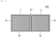
- FIG. 1 is a sectional view for schematically illustrating a schematic configuration of a heat generating element according to a first embodiment of the present invention, as viewed from above.
- FIG. 2 is a perspective view for illustrating a schematic configuration of a first honeycomb structure unit forming the heat generating element illustrated in FIG. 1 .
- a heat generating element 100 includes a first honeycomb structure unit 1 and a second honeycomb structure unit 2.
- the first honeycomb structure unit 1 includes partition walls 14 and an outer peripheral wall 16.
- the partition walls 14 define and form a plurality of cells 12, which extend from a first end surface 10a to a second end surface 10b (in a lengthwise direction), and can serve as fluid flow passages.
- the outer peripheral wall 16 is located on an outer periphery, and surrounds the partition walls 14.
- FIG. 2 shows the first honeycomb structure unit 1 illustrated in FIG. 1 as a representative, the second honeycomb structure unit 2 also has the same configuration.
- the first honeycomb structure unit 1 and the second honeycomb structure unit 2 are arranged such that the respective outer peripheral walls 16 are adjacent to each other so that extending directions of the respective cells 12 (the lengthwise directions) in the first honeycomb structure unit 1 and the second honeycomb structure unit 2 are aligned with each other.
- the term "adjacent" encompasses not only a state of being located side by side directly , but also a state of being located side by side through intermediation of a joining portion.
- the heat generating element includes two honeycomb structure units, but may include three or more honeycomb structure units. When the heat generating element includes three or more honeycomb structure units, honeycomb structure units located side by side may be arranged adjacent to each other.
- the arrangement of the honeycomb structure units is not particularly limited.
- the heat generating element 100 includes a first joining portion 21 provided between the first honeycomb structure unit 1 and the second honeycomb structure unit 2.
- the first honeycomb structure unit 1 and the second honeycomb structure unit 2 are joined to each other through intermediation of the first joining portion 21.
- the heat generating element 100 includes a pair of first electrode portions 31 and 31 that energize and heat the first honeycomb structure unit 1 and the second honeycomb structure unit 2.
- the pair of first electrode portions 31 and 31 are arranged so as to face each other through intermediation of a plurality of honeycomb structure units.
- One first electrode portion 31 of the pair is arranged on the outer peripheral wall 16 of the first honeycomb structure unit 1, and another first electrode portion 31 of the pair is arranged on the outer peripheral wall 16 of the second honeycomb structure unit 2. With such arrangement, for example, a plurality of honeycomb structure units can be caused to uniformly generate heat.
- the outer peripheral wall 16 of the honeycomb structure unit extends in the lengthwise direction.
- the plurality of cells 12 are each defined as a space extending in the lengthwise direction.
- a cross section of each of the cells 12 that is perpendicular to the lengthwise direction has a quadrangular shape, but may have any other polygonal shape, or may have any other shape such as a circular shape.
- a thickness of the partition wall 14 is, for example, from 70 ⁇ m to 500 ⁇ m.
- the number of the cells 12 per unit area in a plane orthogonal to the extending direction of the cells 12 is, for example, from 15 cells/cm 2 to 150 cells/cm 2 .
- the thickness of the partition wall 14 and the number of cells 12 can be measured with, for example, a digital microscope.
- a cross section of the outer peripheral wall 16 that is perpendicular to the lengthwise direction preferably has a rectangular shape or a square shape. With such a shape, a plurality of honeycomb structure units are easily arranged adjacent to each other, and hence extremely excellent assemblability of the heat generating element can be achieved.
- a thickness of the outer peripheral wall 16 is, for example, from 0.5 mm to 5 mm. In the example illustrated in FIG. 1 , the two honeycomb structure units forming the heat generating element have the same shape and size, but the heat generating element may include a plurality of honeycomb structure units having different shapes and sizes. The thickness of the outer peripheral wall 16 can be measured with, for example, a digital microscope.
- a volume resistivity of the honeycomb structure unit is 2 ⁇ cm or more, preferably 10 ⁇ cm or more, more preferably 15 ⁇ cm or more. With such a volume resistivity, a failure such as an excessive electric current flowing, which may be caused depending on the applied voltage, can be prevented. Meanwhile, a volume resistivity of the honeycomb structure unit is, for example, 2,000 ⁇ cm or less, preferably 500 ⁇ cm or less, more preferably 100 ⁇ cm or less. With such a volume resistivity, the honeycomb structure unit can sufficiently generate heat by energization.
- the volume resistivity may be a value measured at a temperature of 400°C using a four-terminal method. Specifically, the measurement is performed as follows. A test piece, which is made of the same material as a material for forming an object to be measured, and has a size of 10 mm in height ⁇ 50 mm in width ⁇ 10 mm in length, is prepared. Silver paste is applied to the entirety of both end surfaces (both end surfaces in the lengthwise direction) of the test piece, followed by wiring of a conductive wire, and under a state in which a thermocouple is placed in a center part of the test piece, voltage is applied to the test piece by using a voltage-applied current measuring device.
- a change over time in temperature of the test piece at the time of the application of the voltage is checked with a recorder, and a current value and a voltage value are measured at the point of time when the test piece has a temperature of 400°C.
- the volume resistivity can be calculated by the test piece size.
- the honeycomb structure unit is preferably made of ceramics. With the adoption of ceramics, the above-mentioned volume resistivity can be satisfactorily satisfied. Further, ceramics has a low thermal expansion coefficient, and hence can have excellent shape stability as well.
- the honeycomb structure unit is made of, for example, a material containing silicon carbide.
- the honeycomb structure unit is preferably made of a material containing a silicon-silicon carbide composite material as a main component.
- the expression "containing as a main component” means that the content of the component in the material is, for example, 80 mass% or more, preferably 90 mass% or more.
- the silicon-silicon carbide composite material may be a material in which a plurality of silicon carbide particles are bonded to each other by metal silicon. In the silicon-silicon carbide composite material, silicon carbide particles may function as aggregate, and silicon may function as a binding material. With the use of the material as described above, the above-mentioned volume resistivity can be satisfactorily achieved.
- a ratio of a mass of silicon to the sum of a mass of silicon carbide particles and the mass of silicon is preferably from 10 mass% to 40 mass%, more preferably from 15 mass% to 35 mass%.
- the volume resistivity of the honeycomb structure unit may also be controlled by adjusting a porosity thereof.
- the honeycomb structure unit can be obtained by drying and firing a molded body obtained by molding of a molding material containing a ceramic raw material.
- the above-mentioned molding material may contain silicon carbide (for example, silicon carbide powder) and metal silicon (for example, metal silicon powder).
- silicon carbide for example, silicon carbide powder
- metal silicon for example, metal silicon powder
- other raw material that may be contained in the molding material include a binder, a dispersant, and an additive.
- the honeycomb structure unit may be used as a catalyst carrier, and a catalyst may be supported on the partition walls 14 of the honeycomb structure unit.
- a catalyst may be supported on the partition walls 14 of the honeycomb structure unit.
- CO, NO x , and a hydrocarbon in a fluid (e.g., gas) passing through the cell 12 can be changed to a harmless substance by a catalytic reaction.
- the catalyst may preferably contain a precious metal (e.g., platinum, rhodium, palladium, ruthenium, indium, silver, or gold), aluminum, nickel, zirconium, titanium, cerium, cobalt, manganese, zinc, copper, tin, iron, niobium, magnesium, lanthanum, samarium, bismuth, barium, and combinations thereof.
- the pair of first electrode portions 31 and 31 are arranged so as to face each other through intermediation of the plurality of honeycomb structure units.
- a formation region of the first electrode portion 31 is not particularly limited, but, for example, the first electrode portion 31 is formed into a band shape extending in the extending direction of the cells 12 in the honeycomb structure unit.
- terminals may be provided to the pair of first electrode portions 31 and 31, respectively. One of the terminals may be connected to a positive pole of a power source, and another one of the terminals may be connected to a negative pole of the power source.
- a thickness of the first electrode portion 31 is, for example, from 100 ⁇ m to 5 mm.
- the volume resistivity of the first electrode portion 31 is preferably from 1 ⁇ 10 -6 ⁇ cm to 1 ⁇ cm, more preferably from 0.01 ⁇ cm to 0.2 ⁇ cm.
- the first electrode portion 31 may include any appropriate material which can satisfy the above-mentioned volume resistivity.
- a metal, conductive ceramics, or a composite material (cermet) of a metal and conductive ceramics may be used as a constituent material of the first electrode portion 31.
- the metal include Cr, Fe, Co, Ni, Si, and Ti. Those materials may be used alone or in combination. When two or more kinds thereof are used in combination, an alloy of two or more kinds of metals may be used.
- the conductive ceramics include: silicon carbide (SiC); and metal compounds, for example, metal silicides, such as tantalum silicide (TaSi 2 ) and chromium silicide (CrSi 2 ).
- the composite material (cermet) of a metal and conductive ceramics include a composite material of a metal silicon and silicon carbide, and a composite material of the metal silicide, a metal silicon, and silicon carbide.
- specific examples of the composite material (cermet) of a metal and conductive ceramics include composite materials obtained by adding one kind or two or more kinds of insulating ceramics, such as alumina, mullite, zirconia, cordierite, silicon nitride, and aluminum nitride, to one kind or two or more kinds of the above-mentioned compounds or a metal from the viewpoint of reducing thermal expansion.
- the first electrode portion 31 be made of a material having the same quality as that of the material of the honeycomb structure unit.
- the first electrode portion 31 be made of a material containing silicon carbide (for example, a material containing a silicon-silicon carbide composite material as a main component).
- a ratio of a mass of silicon to the sum of a mass of silicon carbide particles and the mass of silicon is preferably from 20 mass% to 50 mass%, more preferably from 20 mass% to 40 mass%.
- the volume resistivity of the first electrode portion 31 may be controlled also by adjusting a porosity thereof.
- the first joining portion 21 has a volume resistivity that is lower than the above-mentioned volume resistivity of the honeycomb structure unit.
- the volume resistivity of the first joining portion 21 is 1 ⁇ cm or less, preferably 0.2 ⁇ cm or less.
- the first joining portion 21 which can satisfy the above-mentioned volume resistivity be provided in at least a part of a region in which the first honeycomb structure unit 1 and the second honeycomb structure unit 2 face each other. As illustrated in the figure, the first joining portion 21 is preferably provided over the entire region in which the first honeycomb structure unit 1 and the second honeycomb structure unit 2 face each other.
- a thickness of the first joining portion 21 is, for example, from 500 ⁇ m to 5 mm. The thickness of the first joining portion 21 may correspond to a distance between the first honeycomb structure unit 1 and the second honeycomb structure unit 2.
- the first joining portion 21 may be made of any appropriate material as long as the first joining portion 21 can satisfy the above-mentioned volume resistivity.
- a metal, conductive ceramics, or a composite material (cermet) of a metal and conductive ceramics can be used as a constituent material of the first joining portion 21.
- the metal include Cr, Fe, Co, Ni, Si, and Ti. Those materials may be used alone or in combination. When two or more kinds thereof are used in combination, an alloy of two or more kinds of metals may be used.
- the conductive ceramics include: silicon carbide (SiC); and metal compounds, for example, metal silicides, such as tantalum silicide (TaSi 2 ) and chromium silicide (CrSi 2 ).
- metal silicides such as tantalum silicide (TaSi 2 ) and chromium silicide (CrSi 2 ).
- specific examples of the composite material (cermet) of a metal and conductive ceramics include a composite material of a metal silicon and silicon carbide, and a composite material of the metal silicide, a metal silicon, and silicon carbide.
- specific examples of the composite material (cermet) of a metal and conductive ceramics include composite materials obtained by adding one kind or two or more kinds of insulating ceramics, such as alumina, mullite, zirconia, cordierite, silicon nitride, and aluminum nitride, to one kind or two or more kinds of the above-mentioned compounds or a metal from the viewpoint of reducing thermal expansion.
- insulating ceramics such as alumina, mullite, zirconia, cordierite, silicon nitride, and aluminum nitride
- the first joining portion 21 be made of a material having the same quality as that of the material of the first electrode portion 31. Specifically, it is preferred that the first joining portion 21 contain a component that is contained in the first electrode portion 31. Such a configuration can contribute to an improvement in productivity.
- the first joining portion 21 may be made of a material having the same quality as that of the material of the honeycomb structure unit.
- the first joining portion 21 be made of a material containing silicon carbide (for example, a material containing a silicon-silicon carbide composite material as a main component).
- a ratio of a mass of silicon to the sum of a mass of silicon carbide particles and the mass of silicon is preferably from 20 mass% to 50 mass%, more preferably from 20 mass% to 40 mass%.
- the volume resistivity of the first joining portion 21 may be controlled also by adjusting a porosity thereof.
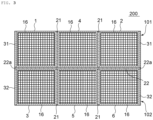
- FIG. 3 is a sectional view for schematically illustrating a schematic configuration of a heat generating element according to a second embodiment of the present invention.
- a heat generating element 200 includes a first heat generating portion 101 and a second heat generating portion 102.
- the first heat generating portion 101 includes a first honeycomb structure unit 1, a second honeycomb structure unit 2, and a fourth honeycomb structure unit 4 arranged between the first honeycomb structure unit 1 and the second honeycomb structure unit 2.
- the first honeycomb structure unit 1, the fourth honeycomb structure unit 4, and the second honeycomb structure unit 2 are arranged such that outer peripheral walls 16 located side by side, among respective outer peripheral walls 16 of the first honeycomb structure unit 1, the fourth honeycomb structure unit 4, and the second honeycomb structure unit 2, are adjacent to each other so that extending directions of the respective cells 12 (the lengthwise directions) in the first honeycomb structure unit 1, the fourth honeycomb structure unit 4, and the second honeycomb structure unit 2 are aligned with each other.
- the first heat generating portion 101 includes: a first joining portion 21 provided between the first honeycomb structure unit 1 and the fourth honeycomb structure unit 4; and a first joining portion 21 provided between the second honeycomb structure unit 2 and the fourth honeycomb structure unit 4.
- the first honeycomb structure unit 1 and the fourth honeycomb structure unit 4 are joined to each other through intermediation of the first joining portion 21 arranged therebetween.
- the second honeycomb structure unit 2 and the fourth honeycomb structure unit 4 are joined to each other through intermediation of the first joining portion 21 arranged therebetween.
- the first heat generating portion 101 includes a pair of first electrode portions 31 and 31 that energize and heat the first honeycomb structure unit 1, the fourth honeycomb structure unit 4, and the second honeycomb structure unit 2.
- One first electrode portion 31 of the pair is provided on the outer peripheral wall 16 of the first honeycomb structure unit 1
- another first electrode portion 31 of the pair is provided on the outer peripheral wall 16 of the second honeycomb structure unit 2.
- the second heat generating portion 102 includes a third honeycomb structure unit 3, a fifth honeycomb structure unit 5, and a sixth honeycomb structure unit 6.
- the third honeycomb structure unit 3, the fifth honeycomb structure unit 5, and the sixth honeycomb structure unit 6 are arranged such that outer peripheral walls 16 located side by side, among respective outer peripheral walls 16 of the third honeycomb structure unit 3, the fifth honeycomb structure unit 5, and the sixth honeycomb structure unit 6, are adjacent to each other so that extending directions of the respective cells 12 (the lengthwise directions) in the third honeycomb structure unit 3, the fifth honeycomb structure unit 5, and the sixth honeycomb structure unit 6 are aligned with each other.
- the second heat generating portion 102 includes: a first joining portion 21 provided between the third honeycomb structure unit 3 and the fifth honeycomb structure unit 5; and a first joining portion 21 provided between the fifth honeycomb structure unit 5 and the sixth honeycomb structure unit 6.
- the third honeycomb structure unit 3 and the fifth honeycomb structure unit 5 are joined to each other through intermediation of the first joining portion 21 arranged therebetween.
- the fifth honeycomb structure unit 5 and the sixth honeycomb structure unit 6 are joined to each other through intermediation of the first joining portion 21 arranged therebetween.
- the second heat generating portion 102 includes a pair of second electrode portions 32 and 32 that energize and heat the third honeycomb structure unit 3, the fifth honeycomb structure unit 5, and the sixth honeycomb structure unit 6.
- the pair of second electrode portions 32 and 32 are arranged so as to face each other through intermediation of a plurality of honeycomb structure units.
- One second electrode portion 32 of the pair is provided on the outer peripheral wall 16 of the third honeycomb structure unit 3, and another second electrode portion 32 of the pair is provided on the outer peripheral wall 16 of the sixth honeycomb structure unit 6.
- the pair of second electrode portions 32 and 32 are arranged so as to face each other through intermediation of the plurality of honeycomb structure units.
- a formation region of the second electrode portion 32 is not particularly limited, but, for example, the second electrode portion 32 is formed into a band shape extending in the extending direction of the cells 12 in the honeycomb structure unit.
- terminals may be provided to the pair of second electrode portions 32 and 32, respectively. One of the terminals may be connected to a positive pole of a power source, and another one of the terminals may be connected to a negative pole of the power source.
- a thickness, a volume resistivity, and a constituent material of the second electrode portion 32 the same description as that given in the first electrode portion 31 as described above can be applied.
- the honeycomb structure units included in the first heat generating portion 101 and the honeycomb structure units included in the second heat generating portion 102 are respectively arranged adjacent to each other so that the extending directions of the respective cells 12 (the lengthwise directions) are aligned with each other.
- the heat generating element 200 includes a second joining portion 22 provided between the first heat generating portion 101 and the second heat generating portion 102.
- the first heat generating portion 101 and the second heat generating portion 102 are joined to each other through intermediation of the second joining portion 22.
- the first honeycomb structure unit 1 and the third honeycomb structure unit 3 are joined to each other through intermediation of the second joining portion 22.
- a volume resistivity of the second joining portion 22 may be set to be higher than the above-mentioned volume resistivity of the honeycomb structure unit.
- the volume resistivity of the second joining portion 22 is preferably 50 ⁇ cm or more, more preferably 200 ⁇ cm or more, still more preferably 1,000 ⁇ cm or more.
- the honeycomb structure unit included in each of the heat generating portions can be caused to effectively generate heat.
- a degree of freedom in shape design of the heat generating element to be obtained can be further increased.
- the volume resistivity of the second joining portion 22 is, for example, 1 ⁇ 10 14 ⁇ cm or less.
- a ratio of the above-mentioned volume resistivity of the honeycomb structure unit to the volume resistivity of the second joining portion 22 is preferably 0.1 or less, more preferably 0.01 or less, still more preferably 0.005 or less. Meanwhile, the ratio of the above-mentioned volume resistivity of the honeycomb structure unit to the volume resistivity of the second joining portion 22 is, for example, 1 ⁇ 10 -13 or more.
- the second joining portion 22 which can satisfy the above-mentioned volume resistivity be provided in at least a part of a region in which the first honeycomb structure unit 1 and the third honeycomb structure unit 3 face each other.
- the second joining portion 22 is preferably provided over the entire region in which the first honeycomb structure unit 1 and the third honeycomb structure unit 3 face each other.
- a thickness of the second joining portion 22 is, for example, from 500 ⁇ m to 5 mm.
- the thickness of the second joining portion 22 may correspond to a distance between the first honeycomb structure unit 1 and the third honeycomb structure unit 3.
- the second joining portion 22 is provided over the entire region in which the first heat generating portion 101 and the second heat generating portion 102 face each other. Further, the first electrode portion 31 of the first heat generating portion 101 and the second electrode portion 32 of the second heat generating portion 102 are separated from each other by the second joining portion 22.
- the second joining portion 22 has end portions 22a each of which is located between the first electrode portion 31 and the second electrode portion 32.
- first electrode portion 31 and the second electrode portion 32 may be electrically connected to each other.
- each of the end portions 22a of the second joining portion 22 may be located within a range in which the honeycomb structure units included in the first heat generating portion 101 and the honeycomb structure units included in the second heat generating portion 102 face each other, and the first electrode portion 31 and the second electrode portion 32 may be electrically connected to each other.
- the second joining portion 22 may be made of any appropriate material which can satisfy the above-mentioned volume resistivity.
- the second joining portion 22 is preferably made of ceramics. With the adoption of ceramics, the above-mentioned volume resistivity can be satisfactorily satisfied.
- the ceramics has a low thermal expansion coefficient, and may also be excellent in shape stability. Examples of the ceramics include cordierite, mullite, alumina, spinel, silicon carbide, silicon nitride, and aluminum titanate. Those ceramics may be used alone or in combination of two or more kinds thereof.
- the present invention is not limited to the above-mentioned embodiments, and various modifications may be made thereto.
- the configurations described in the above-mentioned embodiments may each be replaced by substantially the same configuration, a configuration having the same action and effect, and a configuration that can achieve the same object.
- the heat generating element according to each of the embodiments of the present invention may be used as, for example, a catalyst carrier having a catalyst supported thereon.
- honeycomb structure unit 12 cell, 14 partition wall, 16 outer peripheral wall, 21 first joining portion, 22 second joining portion, 31 first electrode portion, 32 second electrode portion, 100 heat generating element, 101 first heat generating portion, 102 second heat generating portion, 200 heat generating element
Landscapes
- Chemical & Material Sciences (AREA)
- Engineering & Computer Science (AREA)
- Ceramic Engineering (AREA)
- Materials Engineering (AREA)
- Organic Chemistry (AREA)
- Structural Engineering (AREA)
- Chemical Kinetics & Catalysis (AREA)
- Exhaust Gas After Treatment (AREA)
- Catalysts (AREA)
Applications Claiming Priority (2)
| Application Number | Priority Date | Filing Date | Title |
|---|---|---|---|
| JP2022185923 | 2022-11-21 | ||
| PCT/JP2023/036368 WO2024111260A1 (ja) | 2022-11-21 | 2023-10-05 | 発熱体 |
Publications (1)
| Publication Number | Publication Date |
|---|---|
| EP4559576A1 true EP4559576A1 (en) | 2025-05-28 |
Family
ID=91195402
Family Applications (1)
| Application Number | Title | Priority Date | Filing Date |
|---|---|---|---|
| EP23894272.6A Pending EP4559576A1 (en) | 2022-11-21 | 2023-10-05 | Heating element |
Country Status (3)
| Country | Link |
|---|---|
| EP (1) | EP4559576A1 (https=) |
| JP (1) | JPWO2024111260A1 (https=) |
| WO (1) | WO2024111260A1 (https=) |
Family Cites Families (5)
| Publication number | Priority date | Publication date | Assignee | Title |
|---|---|---|---|---|
| US5449541A (en) * | 1992-10-27 | 1995-09-12 | Corning Incorporated | Electrically heatable honeycomb structures |
| JP5992857B2 (ja) * | 2013-03-29 | 2016-09-14 | 日本碍子株式会社 | ハニカム構造体 |
| JP6447901B2 (ja) * | 2014-06-11 | 2019-01-09 | 東海高熱工業株式会社 | 発熱構造体 |
| JP7594398B2 (ja) * | 2020-09-24 | 2024-12-04 | イビデン株式会社 | 電気加熱式触媒 |
| JP7713848B2 (ja) * | 2021-01-15 | 2025-07-28 | 日本碍子株式会社 | セラミックス体及びその製造方法、ヒーターエレメント、ヒーターユニット、ヒーターシステム並びに浄化システム |
-
2023
- 2023-10-05 EP EP23894272.6A patent/EP4559576A1/en active Pending
- 2023-10-05 WO PCT/JP2023/036368 patent/WO2024111260A1/ja not_active Ceased
- 2023-10-05 JP JP2024559994A patent/JPWO2024111260A1/ja active Pending
Also Published As
| Publication number | Publication date |
|---|---|
| WO2024111260A1 (ja) | 2024-05-30 |
| JPWO2024111260A1 (https=) | 2024-05-30 |
Similar Documents
| Publication | Publication Date | Title |
|---|---|---|
| JP5796559B2 (ja) | 電極膜と電極端子 | |
| US20060029898A1 (en) | Firing furnace, porous ceramic member manufacturing method using the same, and porous ceramic member manufactured by the manufacturing method | |
| JP5692198B2 (ja) | ハニカム構造体 | |
| EP0735797B1 (en) | Electrically heatable honeycomb body | |
| JP2014054934A (ja) | ヒーター | |
| EP3574984B1 (en) | Electrically heated catalyst device | |
| CN110354911A (zh) | 电加热型催化剂用载体以及废气净化装置 | |
| US10301992B2 (en) | Heater and honeycomb structure including heater | |
| US10287942B2 (en) | Honeycomb type heating device and method for using the same | |
| EP1596047B1 (en) | Plasma reaction vessel, and method of producing the same | |
| EP4559576A1 (en) | Heating element | |
| JP2011230971A (ja) | 接合体及びその製造方法 | |
| EP4559575A1 (en) | Heating element | |
| JP6093130B2 (ja) | ヒーター | |
| JP7663387B2 (ja) | ハニカム構造体、ならびに該ハニカム構造体を用いた電気加熱式担体および排ガス処理装置 | |
| CN110374728A (zh) | 蜂窝结构体 | |
| JP2025154849A (ja) | ハニカム構造体及びハニカムヒータ | |
| CN116768647A (zh) | 复合烧结体、蜂窝结构体、电加热催化器及复合烧结体的制造方法 | |
| US20220134487A1 (en) | Joined body and method of manufacturing joined body | |
| JP6358822B2 (ja) | 多孔材、接合体、複合体及びそれらの製造方法 | |
| WO2021166309A1 (ja) | 電気加熱式担体及び排気ガス浄化装置 | |
| JP2025154855A (ja) | 三相型ハニカムヒータ | |
| CN115038196B (zh) | 蜂窝结构体、电加热式载体及尾气净化装置 | |
| US20240172332A1 (en) | Electrically heating support | |
| JP2022093013A (ja) | 電気加熱型担体及び排気ガス浄化装置 |
Legal Events
| Date | Code | Title | Description |
|---|---|---|---|
| STAA | Information on the status of an ep patent application or granted ep patent |
Free format text: STATUS: THE INTERNATIONAL PUBLICATION HAS BEEN MADE |
|
| PUAI | Public reference made under article 153(3) epc to a published international application that has entered the european phase |
Free format text: ORIGINAL CODE: 0009012 |
|
| STAA | Information on the status of an ep patent application or granted ep patent |
Free format text: STATUS: REQUEST FOR EXAMINATION WAS MADE |
|
| 17P | Request for examination filed |
Effective date: 20250224 |
|
| AK | Designated contracting states |
Kind code of ref document: A1 Designated state(s): AL AT BE BG CH CY CZ DE DK EE ES FI FR GB GR HR HU IE IS IT LI LT LU LV MC ME MK MT NL NO PL PT RO RS SE SI SK SM TR |
|
| DAV | Request for validation of the european patent (deleted) | ||
| DAX | Request for extension of the european patent (deleted) |