EP4553587A2 - Spiralfeder für uhrwerk - Google Patents
Spiralfeder für uhrwerk Download PDFInfo
- Publication number
- EP4553587A2 EP4553587A2 EP25160457.5A EP25160457A EP4553587A2 EP 4553587 A2 EP4553587 A2 EP 4553587A2 EP 25160457 A EP25160457 A EP 25160457A EP 4553587 A2 EP4553587 A2 EP 4553587A2
- Authority
- EP
- European Patent Office
- Prior art keywords
- spiral spring
- balance
- spring
- button
- spiral
- Prior art date
- Legal status (The legal status is an assumption and is not a legal conclusion. Google has not performed a legal analysis and makes no representation as to the accuracy of the status listed.)
- Pending
Links
Images


Classifications
-
- G—PHYSICS
- G04—HOROLOGY
- G04B—MECHANICALLY-DRIVEN CLOCKS OR WATCHES; MECHANICAL PARTS OF CLOCKS OR WATCHES IN GENERAL; TIME PIECES USING THE POSITION OF THE SUN, MOON OR STARS
- G04B17/00—Mechanisms for stabilising frequency
- G04B17/32—Component parts or constructional details, e.g. collet, stud, virole or piton
- G04B17/34—Component parts or constructional details, e.g. collet, stud, virole or piton for fastening the hairspring onto the balance
-
- G—PHYSICS
- G04—HOROLOGY
- G04B—MECHANICALLY-DRIVEN CLOCKS OR WATCHES; MECHANICAL PARTS OF CLOCKS OR WATCHES IN GENERAL; TIME PIECES USING THE POSITION OF THE SUN, MOON OR STARS
- G04B17/00—Mechanisms for stabilising frequency
- G04B17/32—Component parts or constructional details, e.g. collet, stud, virole or piton
- G04B17/325—Component parts or constructional details, e.g. collet, stud, virole or piton for fastening the hairspring in a fixed position, e.g. using a block
-
- G—PHYSICS
- G04—HOROLOGY
- G04B—MECHANICALLY-DRIVEN CLOCKS OR WATCHES; MECHANICAL PARTS OF CLOCKS OR WATCHES IN GENERAL; TIME PIECES USING THE POSITION OF THE SUN, MOON OR STARS
- G04B18/00—Mechanisms for setting frequency
- G04B18/04—Adjusting the beat of the pendulum, balance, or the like, e.g. putting into beat
-
- G—PHYSICS
- G04—HOROLOGY
- G04B—MECHANICALLY-DRIVEN CLOCKS OR WATCHES; MECHANICAL PARTS OF CLOCKS OR WATCHES IN GENERAL; TIME PIECES USING THE POSITION OF THE SUN, MOON OR STARS
- G04B17/00—Mechanisms for stabilising frequency
- G04B17/04—Oscillators acting by spring tension
- G04B17/06—Oscillators with hairsprings, e.g. balance
- G04B17/066—Manufacture of the spiral spring
-
- G—PHYSICS
- G04—HOROLOGY
- G04B—MECHANICALLY-DRIVEN CLOCKS OR WATCHES; MECHANICAL PARTS OF CLOCKS OR WATCHES IN GENERAL; TIME PIECES USING THE POSITION OF THE SUN, MOON OR STARS
- G04B17/00—Mechanisms for stabilising frequency
- G04B17/32—Component parts or constructional details, e.g. collet, stud, virole or piton
-
- G—PHYSICS
- G04—HOROLOGY
- G04B—MECHANICALLY-DRIVEN CLOCKS OR WATCHES; MECHANICAL PARTS OF CLOCKS OR WATCHES IN GENERAL; TIME PIECES USING THE POSITION OF THE SUN, MOON OR STARS
- G04B18/00—Mechanisms for setting frequency
- G04B18/006—Mechanisms for setting frequency by adjusting the devices fixed on the balance
-
- G—PHYSICS
- G04—HOROLOGY
- G04B—MECHANICALLY-DRIVEN CLOCKS OR WATCHES; MECHANICAL PARTS OF CLOCKS OR WATCHES IN GENERAL; TIME PIECES USING THE POSITION OF THE SUN, MOON OR STARS
- G04B18/00—Mechanisms for setting frequency
- G04B18/02—Regulator or adjustment devices; Indexing devices, e.g. raquettes
- G04B18/026—Locking the hair spring in the indexing device, e.g. goupille of the raquette
-
- G—PHYSICS
- G04—HOROLOGY
- G04B—MECHANICALLY-DRIVEN CLOCKS OR WATCHES; MECHANICAL PARTS OF CLOCKS OR WATCHES IN GENERAL; TIME PIECES USING THE POSITION OF THE SUN, MOON OR STARS
- G04B18/00—Mechanisms for setting frequency
- G04B18/04—Adjusting the beat of the pendulum, balance, or the like, e.g. putting into beat
- G04B18/06—Adjusting the beat of the pendulum, balance, or the like, e.g. putting into beat by setting the collet or the stud of a hairspring
Definitions
- the present invention relates to a spiral spring for a watch movement.
- component will be used to designate a spare part forming part of the device for pinning and adjusting the active length of a spiral spring according to the invention
- part will be used to designate an assembly of two or more "components”.
- the regulating organ is made up of the balance-spring assembly in relation to the escapement.
- These different elements are set in motion thanks to the mechanical energy provided by a barrel spring and carry out the counting and division of time into seconds. It is therefore understood that the precision of the time indication provided by the timepiece with a mechanical movement depends on the precision of the adjustment of the operation of the balance-spring assembly and the escapement.
- a first known technique for ensuring the accuracy of the operation of a balance-spring assembly is to equip the balance with a plurality of weights, for example, fixed in an adjustable manner on the rim of the balance. By adjusting the position of these weights, the inertia of the balance is influenced, which has the effect of modifying the pivoting frequency of this balance-spring assembly.
- Another known technique for ensuring the precision of the operation of a balance-spring assembly consists of equipping this balance-spring assembly with an index assembly comprising at least one index and one racket key which is carried by the racket and which is provided with a slot through which the hairspring passes.
- the racket key can be pivoted on itself, while the racket can be pivoted around the pivot axis of the balance-spring assembly, on a bridge bearing, or around a shock-absorbing bearing.
- the portion of the spiral spring that extends from the racket key to the center of that spiral spring defined by the free end of the last coil inside that spiral spring determines the active length of the spiral spring.
- the portion of the spiral spring that extends between a stud on which the free end of the last coil outside the spiral spring is fixed and the racket key is considered mechanically rigid and does not participate in the oscillations of the balance wheel.
- the position of the racket key defines a so-called counting point.
- the position of this counting point can be modified by pivoting the racket.
- the useful length of the balance spring and therefore the beat frequency of the balance-spring assembly is modified.
- pivoting the racket key on itself the travel of the balance spring is limited inside the slot made in this racket key, taking care, however, not to completely block this balance spring of course. This has the effect of improving the precision of the adjustment of the beat frequency of the balance-spring assembly and therefore the rate precision of this assembly.
- the present invention aims to overcome the drawbacks mentioned above and others by proposing a spiral spring for an improved watch movement.
- the present invention relates to a spiral spring formed from a spiral strip of a determined length for a watch movement, at least a portion of the strip being provided with a scale comprising a plurality of graduations, each of which corresponds to a fraction of time of an advance or a delay of the watch movement.
- the scale comprises graduations which each represent 0.1 s.
- the present invention relates to a device which consists of combining in a single piece at least some of the functions relating to a spiral spring intended to ensure the isochronous beats of a balance of a balance-spring assembly of a watch movement.
- the device firstly comprises a push button arranged so as to immobilize a spiral spring of a watch movement at a point along its length without it being necessary to use glue. From this, it follows that the watch manufacturer enjoys total freedom in terms of the choice of material from which the spiral spring is made and that, in addition, given that the spiral spring is not glued, the device can be dismantled at any time, for example when returning the timepiece to the factory. Consequently, the device already allows, initially, the repositionable pinning of the spiral spring.
- the spiral spring can be immobilized at any point along its length, which allows the active length of this spiral spring to be adjusted, i.e. the distance between the point where the spiral spring is immobilized by the push button and the free end of the first coil inside this spiral spring.
- the device therefore also allows the pivoting frequency of the equipped balance-spring assembly to be adjusted at will. of the device.
- the device is equipped with a pusher holder which allows its fixed mounting, for example, on a bridge of the watch movement, or its pivoting mounting on a support such as a balance bridge or a bearing carried by this bridge.
- the device thus fulfills four distinct functions: the repositionable pitonnage of the balance spring, the mounting of the piton holder on its support, the adjustment of the active length of this same balance spring, and the adjustment of the balance marker.
- the device consisting of a single piece formed, in a simplified variant, of a tube, a button and an elastic member, therefore advantageously replaces the assembly of components such as a stud, stud holder, index, index key, index tail and eccentric, which makes it possible to reduce the number of components necessary for fixing the balance spring and adjusting the pivoting frequency of the balance-spring assembly, and facilitates the assembly of the device in the watch movement due to its reduced size.
- Another advantage of this device lies in the fact that it eliminates the need for glue.
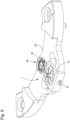
- the device 1 allows the winding of a spiral spring 2 for a watch movement, as well as the adjustment of an active length of this spiral spring 2.
- the spiral spring 2 arranged in turns, has a determined length between a free end of a first turn on the inside and a free end of a last turn on the outside 3.
- the spiral spring 2 can be shaped as a flat strip delimited by first and second faces which extend parallel to and at a distance from each other.
- the device 1 makes it possible to immobilize, advantageously in a removable manner as described below, the spiral spring 2 at any point along its length, and to adjust the length which separates a point 4 where this spiral spring 2 is immobilized from the free end of the first turn inside this same spiral spring 2.
- the device 1 firstly comprises a push button 6 arranged to releasably hold the spiral spring 2 at a location along the length of the band of this spiral spring 2.
- the push button 6 essentially comprises a button 8 and a tube 10 in which the button 8 is able to slide.
- the button 8 is elastically returned to a rest position by an elastic member 12 of the spring or elastic blade type (see, in particular, the Figure 1 ).
- the button 8 is, in a service position, kept away from its rest position by interposition of a portion of the spiral spring 2 between the button 8 and the tube 10, which ensures the mechanical immobilization of the spiral spring 2.
- the spiral spring 2 can be released at any time from its grip with the push button 6. To do this, it is sufficient to exert pressure on the button 8 that counteracts the return force of the elastic member 12 in order to make it come out further from the tube 10.
- the stiffness coefficient of the elastic member 12 it is possible to precisely control the pinching force that is exerted on the spiral spring 2 when the latter is held stationary between the button 8 and the tube 10 of the push button 6. Consequently, the risks of breaking the spiral spring 2, in particular when it is made of silicon, are limited.
- the button 8 extends between a head 14 and a foot 16 in which a groove 18 is formed which goes at least partially around the foot 16.
- the spiral spring 2 is passed around of the foot 16 of the button 8 in its portion where it is desired that it be immobilized by the push button 6 by pinching between the foot 16 of the button 8 and the opposite end of the tube 10.
- the spiral spring 2 is thus pinched between the foot 16 of the button 8 and the opposite end of the tube 10 at two points, which allows the push button 6 to transmit a holding torque to the spiral spring 2 so that this spiral spring 2 does not slip or rotate around its fixing point during the life of the timepiece.
- the device 1 and its push button 6 are simply fixed on a bridge 20 of a plate of the watch movement, typically by means of a screw 21.
- the device 1 for the pinning and adjustment of the active length of the spiral spring 2 further comprises a push-button holder 22 which carries the push-button 6, as well as a balance 24 forming part of a balance-spring assembly 26.
- the push-button holder 22 is arranged to be able to pivot around a pivot axis D of the balance-spring assembly 26 of the watch movement.
- the pusher holder 22 is provided with an opening 28 whose internal diameter is adjusted to the external diameter of the pivot axis D of the balance-spring assembly 26.
- the device 1 thus advantageously fulfills both the function of stud and stud holder.
- the balance-spring assembly 26 is preferably pivoted in a shock-absorbing bearing 30 conventionally comprising a setting 32, a holed jewel 34, a counter-pivot jewel 36 and a spring 38.
- the spiral spring 2 comprises on at least a portion of the spiral band forming this spiral spring 2 a scale 40 of which each graduation represents for example a variation of 0.1 s as is visible on the Figures 3 and 4 .
- the pivoting of the balance 24 will also cause the displacement of the marker which can then be realigned by rotating the device 1 which is composed of the push-button 6 and the push-holder 22 carrying the push-button 6. It will of course be understood that this operation is not possible in the case of the simplified embodiment of the invention illustrated in Figure 5 . It will also be noted that by push button we mean an assembly formed of a cylinder and a tube inside which the cylinder is able to slide against the elastic restoring force of a spring. It will also be noted that, as already mentioned above, the immobilization of the spiral spring 2 is done at two points located one on the terminal curve and the other in the region where the scale can be provided.
Landscapes
- Physics & Mathematics (AREA)
- General Physics & Mathematics (AREA)
- Engineering & Computer Science (AREA)
- Manufacturing & Machinery (AREA)
- Springs (AREA)
- Electric Clocks (AREA)
Priority Applications (1)
| Application Number | Priority Date | Filing Date | Title |
|---|---|---|---|
| EP25160457.5A EP4553587A3 (de) | 2023-01-31 | 2023-01-31 | Spiralfeder für uhrwerk |
Applications Claiming Priority (2)
| Application Number | Priority Date | Filing Date | Title |
|---|---|---|---|
| EP25160457.5A EP4553587A3 (de) | 2023-01-31 | 2023-01-31 | Spiralfeder für uhrwerk |
| EP23154309.1A EP4411489A1 (de) | 2023-01-31 | 2023-01-31 | Vorrichtung zum einstellen und einstellen der aktiven länge einer spiralfeder für uhrwerk, und verfahren zum einstellen der aktiven länge |
Related Parent Applications (1)
| Application Number | Title | Priority Date | Filing Date |
|---|---|---|---|
| EP23154309.1A Division EP4411489A1 (de) | 2023-01-31 | 2023-01-31 | Vorrichtung zum einstellen und einstellen der aktiven länge einer spiralfeder für uhrwerk, und verfahren zum einstellen der aktiven länge |
Publications (2)
| Publication Number | Publication Date |
|---|---|
| EP4553587A2 true EP4553587A2 (de) | 2025-05-14 |
| EP4553587A3 EP4553587A3 (de) | 2025-07-16 |
Family
ID=85150316
Family Applications (2)
| Application Number | Title | Priority Date | Filing Date |
|---|---|---|---|
| EP25160457.5A Pending EP4553587A3 (de) | 2023-01-31 | 2023-01-31 | Spiralfeder für uhrwerk |
| EP23154309.1A Pending EP4411489A1 (de) | 2023-01-31 | 2023-01-31 | Vorrichtung zum einstellen und einstellen der aktiven länge einer spiralfeder für uhrwerk, und verfahren zum einstellen der aktiven länge |
Family Applications After (1)
| Application Number | Title | Priority Date | Filing Date |
|---|---|---|---|
| EP23154309.1A Pending EP4411489A1 (de) | 2023-01-31 | 2023-01-31 | Vorrichtung zum einstellen und einstellen der aktiven länge einer spiralfeder für uhrwerk, und verfahren zum einstellen der aktiven länge |
Country Status (5)
| Country | Link |
|---|---|
| US (1) | US20240255896A1 (de) |
| EP (2) | EP4553587A3 (de) |
| JP (1) | JP7665003B2 (de) |
| KR (1) | KR20240120657A (de) |
| CN (2) | CN118426285A (de) |
Family Cites Families (6)
| Publication number | Priority date | Publication date | Assignee | Title |
|---|---|---|---|---|
| CH321947A (fr) * | 1955-08-20 | 1957-05-31 | Etienne Fernand | Dispositif de réglage de la position de la raquette d'une pièce d'horlogerie |
| US3553956A (en) * | 1969-09-11 | 1971-01-12 | Timex Corp | Double hairspring clamping device |
| JPS5026862U (de) * | 1973-07-04 | 1975-03-27 | ||
| JPS5263062U (de) * | 1975-11-05 | 1977-05-10 | ||
| CH692532A5 (fr) * | 1997-10-21 | 2002-07-15 | Ebauchesfabrik Eta Ag | Procédé de fabrication d'un spiral de balancier pour mouvement d'horlogerie. |
| EP2881804B1 (de) * | 2013-12-09 | 2017-08-02 | Montres Breguet S.A. | Spiralfeder-spiralklötzchen-einheit für uhrwerk |
-
2023
- 2023-01-31 EP EP25160457.5A patent/EP4553587A3/de active Pending
- 2023-01-31 EP EP23154309.1A patent/EP4411489A1/de active Pending
- 2023-12-20 JP JP2023214961A patent/JP7665003B2/ja active Active
- 2023-12-27 US US18/397,554 patent/US20240255896A1/en active Pending
-
2024
- 2024-01-02 CN CN202410002542.6A patent/CN118426285A/zh active Pending
- 2024-01-02 CN CN202420004123.1U patent/CN221668195U/zh active Active
- 2024-01-18 KR KR1020240008262A patent/KR20240120657A/ko active Pending
Also Published As
| Publication number | Publication date |
|---|---|
| JP2024109045A (ja) | 2024-08-13 |
| JP7665003B2 (ja) | 2025-04-18 |
| CN221668195U (zh) | 2024-09-06 |
| EP4411489A1 (de) | 2024-08-07 |
| CN118426285A (zh) | 2024-08-02 |
| KR20240120657A (ko) | 2024-08-07 |
| US20240255896A1 (en) | 2024-08-01 |
| EP4553587A3 (de) | 2025-07-16 |
Similar Documents
| Publication | Publication Date | Title |
|---|---|---|
| EP4009115A1 (de) | Spiralfeder für resonatormechanismus eines uhrwerks, der mit mitteln zum ausgleichen der starrheit ausgestattet ist | |
| EP3502788B1 (de) | Vorrichtung zur selbstregulierung der aktiven länge einer spirale | |
| EP4187326A1 (de) | Spiralfeder für resonatormechanismus eines uhrwerks, der mit mitteln zum ausgleichen der starrheit ausgestattet ist | |
| EP4286962B1 (de) | Regulierorgan für uhr, das eine rückervorrichtung umfasst, die mit verriegelungsmitteln ausgestattet ist | |
| CH718113B1 (fr) | Ressort-spiral pour mécanisme résonateur d'horlogerie muni de moyens d'ajustement de la rigidité | |
| CH712225B1 (fr) | Dispositif régulateur comportant un organe de correction d'anisochronisme. | |
| EP4286960B1 (de) | Regulierorgan für uhr, das mit einer rückervorrichtung ausgestattet ist | |
| CH719990B1 (fr) | Dispositif de pitonnage et d'ajustement de la longueur active d'un ressort spiral pour mouvement horloger ainsi que procédé de réglage de la longueur active | |
| EP4194959B1 (de) | Natürliche hemmung für uhrwerk und uhrwerk, das eine solche uhrhemmung umfasst | |
| EP4553587A2 (de) | Spiralfeder für uhrwerk | |
| EP4428626B1 (de) | Vorrichtung zur autonomen einstellung der aktiven länge einer spiralfeder | |
| EP3407142A1 (de) | Uhrwerk mit sekunden-stopp-funktion | |
| EP4428624B1 (de) | Vorrichtung zur autonomen einstellung der aktiven länge einer spiralfeder | |
| EP4575668A1 (de) | Uhranordnung für ein regulierorgan mit mitteln zur gangeinstellung | |
| CH721430A2 (fr) | Ensemble d'horlogerie pour organe réglant muni de moyens d'ajustement de la marche | |
| EP4134754A1 (de) | Trägheitsmasse, die mit einem flexiblen trägheitselement ausgestattet ist, insbesondere für uhrwerke | |
| EP4557015A1 (de) | Regulierorgan für uhr, das ein betätigungssystem mit einem exzenter umfasst | |
| CH720583A2 (fr) | Dispositif de réglage autonome de la longueur active d'un spiral | |
| EP4546058A1 (de) | Spiralfeder für resonatormechanismus einer uhr mit symmetrischen steifigkeitseinstellmitteln | |
| CH721296A2 (fr) | Organe réglant d'horlogerie comprenant un système d'actionnement muni d'un excentrique | |
| CH720582A2 (fr) | Dispositif de réglage autonome de la longueur active d'un spiral | |
| CH720982A2 (fr) | Organe réglant d'horlogerie comprenant un système d'actionnement muni d'une bascule de commande | |
| EP4498176A1 (de) | Regulierungsorgan für uhren, das mit einem linearem betätigungssystem augerustet ist | |
| EP4521173A1 (de) | Uhrvorrichtung | |
| EP4372480A1 (de) | Uhranordnung mit spiralfeder und stepper |
Legal Events
| Date | Code | Title | Description |
|---|---|---|---|
| PUAI | Public reference made under article 153(3) epc to a published international application that has entered the european phase |
Free format text: ORIGINAL CODE: 0009012 |
|
| STAA | Information on the status of an ep patent application or granted ep patent |
Free format text: STATUS: THE APPLICATION HAS BEEN PUBLISHED |
|
| AC | Divisional application: reference to earlier application |
Ref document number: 4411489 Country of ref document: EP Kind code of ref document: P |
|
| AK | Designated contracting states |
Kind code of ref document: A2 Designated state(s): AL AT BE BG CH CY CZ DE DK EE ES FI FR GB GR HR HU IE IS IT LI LT LU LV MC ME MK MT NL NO PL PT RO RS SE SI SK SM TR |
|
| REG | Reference to a national code |
Ref country code: DE Ref legal event code: R079 Free format text: PREVIOUS MAIN CLASS: G04B0017060000 Ipc: G04B0017320000 |
|
| PUAL | Search report despatched |
Free format text: ORIGINAL CODE: 0009013 |
|
| AK | Designated contracting states |
Kind code of ref document: A3 Designated state(s): AL AT BE BG CH CY CZ DE DK EE ES FI FR GB GR HR HU IE IS IT LI LT LU LV MC ME MK MT NL NO PL PT RO RS SE SI SK SM TR |
|
| RIC1 | Information provided on ipc code assigned before grant |
Ipc: G04B 17/32 20060101AFI20250610BHEP Ipc: G04B 18/02 20060101ALI20250610BHEP Ipc: G04B 17/06 20060101ALI20250610BHEP |
|
| P01 | Opt-out of the competence of the unified patent court (upc) registered |
Free format text: CASE NUMBER: APP_29215/2025 Effective date: 20250618 |
|
| STAA | Information on the status of an ep patent application or granted ep patent |
Free format text: STATUS: REQUEST FOR EXAMINATION WAS MADE |
|
| 17P | Request for examination filed |
Effective date: 20260116 |