EP4411489A1 - Vorrichtung zum einstellen und einstellen der aktiven länge einer spiralfeder für uhrwerk, und verfahren zum einstellen der aktiven länge - Google Patents
Vorrichtung zum einstellen und einstellen der aktiven länge einer spiralfeder für uhrwerk, und verfahren zum einstellen der aktiven länge Download PDFInfo
- Publication number
- EP4411489A1 EP4411489A1 EP23154309.1A EP23154309A EP4411489A1 EP 4411489 A1 EP4411489 A1 EP 4411489A1 EP 23154309 A EP23154309 A EP 23154309A EP 4411489 A1 EP4411489 A1 EP 4411489A1
- Authority
- EP
- European Patent Office
- Prior art keywords
- spiral spring
- button
- spring
- balance
- watch movement
- Prior art date
- Legal status (The legal status is an assumption and is not a legal conclusion. Google has not performed a legal analysis and makes no representation as to the accuracy of the status listed.)
- Pending
Links
Images


Classifications
-
- G—PHYSICS
- G04—HOROLOGY
- G04B—MECHANICALLY-DRIVEN CLOCKS OR WATCHES; MECHANICAL PARTS OF CLOCKS OR WATCHES IN GENERAL; TIME PIECES USING THE POSITION OF THE SUN, MOON OR STARS
- G04B17/00—Mechanisms for stabilising frequency
- G04B17/32—Component parts or constructional details, e.g. collet, stud, virole or piton
- G04B17/325—Component parts or constructional details, e.g. collet, stud, virole or piton for fastening the hairspring in a fixed position, e.g. using a block
-
- G—PHYSICS
- G04—HOROLOGY
- G04B—MECHANICALLY-DRIVEN CLOCKS OR WATCHES; MECHANICAL PARTS OF CLOCKS OR WATCHES IN GENERAL; TIME PIECES USING THE POSITION OF THE SUN, MOON OR STARS
- G04B18/00—Mechanisms for setting frequency
- G04B18/04—Adjusting the beat of the pendulum, balance, or the like, e.g. putting into beat
-
- G—PHYSICS
- G04—HOROLOGY
- G04B—MECHANICALLY-DRIVEN CLOCKS OR WATCHES; MECHANICAL PARTS OF CLOCKS OR WATCHES IN GENERAL; TIME PIECES USING THE POSITION OF THE SUN, MOON OR STARS
- G04B17/00—Mechanisms for stabilising frequency
- G04B17/32—Component parts or constructional details, e.g. collet, stud, virole or piton
- G04B17/34—Component parts or constructional details, e.g. collet, stud, virole or piton for fastening the hairspring onto the balance
-
- G—PHYSICS
- G04—HOROLOGY
- G04B—MECHANICALLY-DRIVEN CLOCKS OR WATCHES; MECHANICAL PARTS OF CLOCKS OR WATCHES IN GENERAL; TIME PIECES USING THE POSITION OF THE SUN, MOON OR STARS
- G04B17/00—Mechanisms for stabilising frequency
- G04B17/04—Oscillators acting by spring tension
- G04B17/06—Oscillators with hairsprings, e.g. balance
- G04B17/066—Manufacture of the spiral spring
-
- G—PHYSICS
- G04—HOROLOGY
- G04B—MECHANICALLY-DRIVEN CLOCKS OR WATCHES; MECHANICAL PARTS OF CLOCKS OR WATCHES IN GENERAL; TIME PIECES USING THE POSITION OF THE SUN, MOON OR STARS
- G04B17/00—Mechanisms for stabilising frequency
- G04B17/32—Component parts or constructional details, e.g. collet, stud, virole or piton
-
- G—PHYSICS
- G04—HOROLOGY
- G04B—MECHANICALLY-DRIVEN CLOCKS OR WATCHES; MECHANICAL PARTS OF CLOCKS OR WATCHES IN GENERAL; TIME PIECES USING THE POSITION OF THE SUN, MOON OR STARS
- G04B18/00—Mechanisms for setting frequency
- G04B18/006—Mechanisms for setting frequency by adjusting the devices fixed on the balance
-
- G—PHYSICS
- G04—HOROLOGY
- G04B—MECHANICALLY-DRIVEN CLOCKS OR WATCHES; MECHANICAL PARTS OF CLOCKS OR WATCHES IN GENERAL; TIME PIECES USING THE POSITION OF THE SUN, MOON OR STARS
- G04B18/00—Mechanisms for setting frequency
- G04B18/02—Regulator or adjustment devices; Indexing devices, e.g. raquettes
- G04B18/026—Locking the hair spring in the indexing device, e.g. goupille of the raquette
-
- G—PHYSICS
- G04—HOROLOGY
- G04B—MECHANICALLY-DRIVEN CLOCKS OR WATCHES; MECHANICAL PARTS OF CLOCKS OR WATCHES IN GENERAL; TIME PIECES USING THE POSITION OF THE SUN, MOON OR STARS
- G04B18/00—Mechanisms for setting frequency
- G04B18/04—Adjusting the beat of the pendulum, balance, or the like, e.g. putting into beat
- G04B18/06—Adjusting the beat of the pendulum, balance, or the like, e.g. putting into beat by setting the collet or the stud of a hairspring
Definitions
- the present invention relates to a device for pinning and adjusting the active length of a spiral spring for a watch movement.
- component a spare part entering into the composition of the device for pinning and adjusting the active length of a spiral spring according to the invention, and by “part” a assembly of two or more “components”.
- the regulating organ is constituted by the balance-spring assembly in relation to the escapement.
- These different elements are set in motion thanks to the mechanical energy provided by a barrel spring and perform the counting and division of time in seconds.
- the precision of the time indication provided by the timepiece with mechanical movement depends on the precision of the adjustment of the operation of the balance-spring assembly and the escapement.
- a first known technique for ensuring the precision of the operation of a balance-spring assembly is to provide the balance with a plurality of weights, for example fixed in an adjustable manner on the rim of the balance. By adjusting the position of these weights, we influence the inertia of the balance, which has the effect of modifying the pivoting frequency of this balance-spring assembly.
- Another known technique for ensuring the precision of the operation of a balance-spring assembly consists of equipping this balance-spring assembly with a racket comprising at least one racket and a racket key which is carried by the racket and which is provided a slot through which the hairspring passes.
- the racket key can be pivoted on itself, while the racket can be pivoted around the pivot axis of the balance-spring assembly, on a span of a bridge, or around a shock absorber bearing of shocks.
- the portion of the spiral spring which extends from the racket key to the center of this spiral spring defined by the free end of the last turn inside this spiral spring determines the active length of the spiral spring.
- the portion of the spiral spring which extends between a pin on which is fixed the free end of the last turn outside the spiral spring and the racket key is considered mechanically rigid and does not participate in the oscillations of the balance.
- the position of the racket key defines a so-called counting point.
- the position of this counting point can be changed by rotating the racket.
- we pivoting the racket key on itself we limit the movement of the spiral spring inside the slot provided in this racket key, taking care not to completely block this spiral spring of course. This has the effect of improving the precision of the adjustment of the beat frequency of the balance-spring assembly and therefore the running precision of this assembly.
- the present invention aims to overcome the drawbacks mentioned above as well as others by proposing a simpler and more economical device allowing both the pinning and the adjustment of the active length of a spiral spring of a watch movement.
- the present invention relates to a device for pinning and adjusting an active length of a spiral spring for a watch movement, this spiral spring being formed of a spiral strip of a determined length, this device comprising a push button arranged to mechanically hold the spiral spring at a location along the length of the band of this spiral spring.
- the push button consists of a button and a tube in which the button is able to slide, the button being elastically returned to a rest position by an elastic member , the button being, in a service position, kept away from its rest position by the interposition of a portion of the strip of the spiral spring between the button and the tube, which ensures the mechanical retention of the spiral spring.
- the button extends between a head and a foot in which a groove is provided which at least partially goes around the foot and in which is engaged a portion of the spiral spring at the place where it is desired for this spiral spring to be immobilized by pinching between the foot of the button and one end facing the tube at two distinct points, so as to allow the push button to transmit a holding torque to the spiral spring so that this spiral spring does not slip or rotate around its fixing point during the life of the timepiece.
- the groove extends over an entire outer perimeter of the button.
- the elastic member is a spring.
- the spring is an elastic blade.
- the button is provided with a groove in which is engaged the portion of the band of the spiral spring whose presence ensures that the button is maintained in the operating position.
- the groove extends over an entire outer perimeter of the button.
- the push button is fixed on a bridge of the watch movement.
- the device for pinning and adjusting the active length of the spiral spring comprises a push-piece component which carries the push-button, this push-piece component being arranged to be able to pivot around a pivot axis of a balance-spring assembly of the watch movement.
- the pusher holder is pivotally mounted on a support.
- the support is a balance bridge or a bearing carried by this bridge.
- the bearing is a shock absorbing bearing.
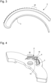
- a scale comprising a plurality of graduations each of which corresponds to a fraction of time of an advance or a delay of the watch movement is transferred to a bridge of a plate of the watch movement or on the plate.
- the invention relates to a spiral spring formed of a spiral band of a determined length for a watch movement, at least one portion of the band being provided with a scale comprising a plurality of graduations including each corresponds to a fraction of time of an advance or a delay of the watch movement.
- the scale comprises graduations which each represent 0.1s.
- the invention also relates to a method for adjusting the active length of a spiral spring of a watch movement by means of the device according to the invention, in which, to adjust the active length of the spiral spring, the spiral spring is momentarily released. by pressing the push button, then we rotate a balance whose beats are ensured by the spiral spring at a desired angle, then we release the pressure on the push button to again immobilize the spiral spring, the pivoting of the pendulum causing the movement of a marker which is then realigned by rotating the device.
- the present invention provides a device allowing both to pin a spiral spring of a watch movement and to adjust its active length in order to precisely adjust the pivoting frequency of the balance spring.
- the spiral spring being hammered without using glue, it can be repositioned at any time so that, if necessary, the pivoting frequency of the sprung balance can be adjusted during the life of the timepiece, for example when returning at the factory.
- the watch manufacturer enjoys complete freedom in the choice of the material from which the spiral spring is made.
- the device according to the invention thus advantageously makes it possible to combine the functions of piton and racket, which makes it possible to reduce the number of necessary components and to simplify the integration of the device according to the invention into a watch movement due to its reduced size.
- the device comprises a pusher-carrying part thanks to which the eyebolt and adjustment device can be pivotally mounted around a pivot axis of a balance assembly.
- -spring which allows the balance marker to be adjusted.
- the present invention provides a device which, by means of a single part, makes it possible to group up to four distinct functions for a spiral spring of a watch movement which a priori seem incompatible with each other. , namely: repositionable eyebolt, assembly of the eyebolt holder on its support, adjustment of the active length and adjustment of the mark.
- the fixing point of the spiral spring is conventionally provided by a eyebolt while the adjustment of the counting point is carried out by means of a racket key.
- the device makes it possible to group together in a single point both the fixing point of the spiral spring and the counting point.
- One of the advantages of this device is that it can thus allow, in a simplified form of execution of the invention, to use a balance wheel. the balance-spring assembly which does not have its own means of adjusting its inertia, which makes it possible to achieve substantial savings.
- the present invention proceeds from the general inventive idea which consists of bringing together in a single piece at least part of the functions relating to a spiral spring intended to ensure the isochronous beats of a balance of a balance-spring assembly of a watch movement.
- the present invention provides a device comprising firstly a push button arranged so as to immobilize a spiral spring of a watch movement at a location along its length without it being necessary to resort to force. glue. From this, it follows that the watch manufacturer enjoys complete freedom with regard to the choice of the material from which the spiral spring is made and that, moreover, given that the spiral spring is not glued, the device according to the invention can be dismantled at any time, for example when returning the timepiece to the factory.
- the device according to the invention already allows, initially, the repositionable pinning of the spiral spring.
- the spiral spring can be immobilized at any point along its length, which allows the active length of this spiral spring to be adjusted, i.e. -say the distance which separates the point where the spiral spring is immobilized by the push button from the free end of the first turn inside this spiral spring.
- the device according to the invention therefore also makes it possible to adjust as desired the pivoting frequency of the balance-spring assembly equipped with the device according to the invention.
- the device according to the invention is equipped with a pusher holder which allows its fixed mounting for example on a bridge of the watch movement, or its pivoting mounting on a support such as a balance bridge or a bearing carried by this bridge.
- the device according to the invention thus fulfills four distinct functions: the repositionable eyebolt of the spiral spring, the mounting of the eyebolt holder on its support, the adjustment of the active length of this same spiral spring, and the adjustment of the balance mark.
- the device according to the invention consisting of a single part formed, in a simplified execution variant, of a tube, a button and an elastic member, therefore advantageously replaces the assembly of components of the prior art such as piton, piton holder, racket, racket key, racket tail and eccentric, which makes it possible to reduce the number of components necessary for fixing the spiral spring and adjusting the pivoting frequency of the balance-spring assembly, and facilitates the mounting of the device according to the invention in the watch movement due to of its reduced size.
- Another decisive advantage of the invention lies in the fact that it makes it possible to dispense with any use of glue.
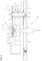
- the device according to the invention is shown in top view at the figure 1 , and in section along line II-II of the figure 1 to the figure 2 .
- the device 1 allows the pinning of a spiral spring 2 for a watch movement, as well as the adjustment of an active length of this spiral spring 2.
- the spiral spring 2 arranged in turns, has a determined length between a free end of a first turn on the inside and a free end of a last turn on the outside 3.
- the spiral spring 2 can be shaped into a flat strip delimited by first and second faces which extend parallel to and at a distance from each other.
- the device 1 makes it possible to immobilize, advantageously in a removable manner as described below, the spiral spring 2 at any location along its length, and to adjust the length which separates a point 4 where this spring spiral 2 is immobilized from the free end of the first turn inside this same spiral spring 2.
- the device 1 firstly comprises a push button 6 arranged to releasably hold the spiral spring 2 at a location along the length of the strip of this spiral spring 2.
- the push button 6 essentially comprises a button 8 and a tube 10 in which the button 8 is capable of slide.
- the button 8 is elastically returned to a rest position by an elastic member 12 of the type of a spring or an elastic blade (see, in particular, the figure 1 ).
- the button 8 is, in a service position, kept away from its rest position by interposing a portion of the spiral spring 2 between the button 8 and the tube 10, which ensures the mechanical immobilization of the spiral spring 2.
- the spiral spring 2 can be released from its grip with the push button 6 at any time. To do this, it is enough to press the button 8 pressure going against the restoring force of the elastic member 12 in order to make it exit further from the tube 10.
- the button 8 extends between a head 14 and a foot 16 in which a groove 18 is provided which at least partially goes around the foot 16. Consequently, the spiral spring 2 is passed around the foot 16 of the button 8 in its portion where we want it to be immobilized by the push button 6 by pinching between the foot 16 of the button 8 and the opposite end of the tube 10. The spiral spring 2 is thus pinched between the foot 16 of the button 8 and the opposite end of the tube 10 at two points, which allows the push button 6 to transmit a holding torque to the spiral spring 2 so that this spiral spring 2 does not slip or does not rotate around its point of attachment. fixation during the life of the timepiece.
- the device 1 according to the invention and its push button 6 are simply fixed on a bridge 20 of a plate of the watch movement, typically by means of a screw 21.
- the device 1 for bolting and adjusting the active length of the spiral spring 2 further comprises a push-piece holder 22 which carries the push-button 6, as well as a balance wheel. 24 forming part of a balance-spring assembly 26.
- the push-piece holder 22 is arranged to be able to pivot around a pivot axis D of the balance-spring assembly 26 of the watch movement.
- the pusher holder 22 is provided with an opening 28 whose internal diameter is adjusted to the external diameter of the pivot axis D of the balance-spring assembly 26.
- the device 1 according to the invention fulfills thus advantageously both the function of eyebolt and eyebolt holder.
- the balance-spring assembly 26 is preferably pivoted in a shock-absorbing bearing 30 conventionally comprising a bezel 32, a stone with a hole 34, a counter-pivot stone 36 and a spring 38.
- the balance-spring assembly 26 is moved to induce a delay by passing 10 graduations of 0.1 s in front of an index 42. Then we release the pressure on button 8 of push button 6 to again immobilize the spiral spring 2.
- the pivoting of the balance 24 will also cause the movement of the mark which can then be realigned by rotating the device 1 which consists of the push button 6 and the push button 22 carrying the push button 6. It will of course be understood that this operation is not possible in the case of the simplified form of execution of the invention illustrated in figure 5 .
- the term "push button” means an assembly formed of a cylinder and a tube inside which the cylinder is able to slide against the restoring force. elastic of a spring. It will also be noted that, as already mentioned above, the immobilization of the spiral spring 2 is done at two points located, one on the terminal curve and the other in the region where the scale can be provided.
Landscapes
- Physics & Mathematics (AREA)
- General Physics & Mathematics (AREA)
- Engineering & Computer Science (AREA)
- Manufacturing & Machinery (AREA)
- Springs (AREA)
- Electric Clocks (AREA)
Priority Applications (7)
| Application Number | Priority Date | Filing Date | Title |
|---|---|---|---|
| EP25160457.5A EP4553587A3 (de) | 2023-01-31 | 2023-01-31 | Spiralfeder für uhrwerk |
| EP23154309.1A EP4411489A1 (de) | 2023-01-31 | 2023-01-31 | Vorrichtung zum einstellen und einstellen der aktiven länge einer spiralfeder für uhrwerk, und verfahren zum einstellen der aktiven länge |
| JP2023214961A JP7665003B2 (ja) | 2023-01-31 | 2023-12-20 | 時計ムーブメント用のヒゲゼンマイをスタッドにピン止めしかつその有効長を調整する装置及び有効長を設定する方法 |
| US18/397,554 US20240255896A1 (en) | 2023-01-31 | 2023-12-27 | Device for pinning up to the stud and adjusting the active length of a balance-spring for a horological movement and process for setting the active length |
| CN202420004123.1U CN221668195U (zh) | 2023-01-31 | 2024-01-02 | 固定和设置装置以及用于钟表机芯的游丝 |
| CN202410002542.6A CN118426285A (zh) | 2023-01-31 | 2024-01-02 | 固定游丝并调节其有效长度的装置及设置有效长度的方法 |
| KR1020240008262A KR20240120657A (ko) | 2023-01-31 | 2024-01-18 | 측시 무브먼트를 위한 밸런스 스프링의 활성 길이를 조정하고 스터드에 핀고정하기 위한 디바이스 및 활성 길이를 세팅하기 위한 방법 |
Applications Claiming Priority (1)
| Application Number | Priority Date | Filing Date | Title |
|---|---|---|---|
| EP23154309.1A EP4411489A1 (de) | 2023-01-31 | 2023-01-31 | Vorrichtung zum einstellen und einstellen der aktiven länge einer spiralfeder für uhrwerk, und verfahren zum einstellen der aktiven länge |
Related Child Applications (1)
| Application Number | Title | Priority Date | Filing Date |
|---|---|---|---|
| EP25160457.5A Division EP4553587A3 (de) | 2023-01-31 | 2023-01-31 | Spiralfeder für uhrwerk |
Publications (1)
| Publication Number | Publication Date |
|---|---|
| EP4411489A1 true EP4411489A1 (de) | 2024-08-07 |
Family
ID=85150316
Family Applications (2)
| Application Number | Title | Priority Date | Filing Date |
|---|---|---|---|
| EP25160457.5A Pending EP4553587A3 (de) | 2023-01-31 | 2023-01-31 | Spiralfeder für uhrwerk |
| EP23154309.1A Pending EP4411489A1 (de) | 2023-01-31 | 2023-01-31 | Vorrichtung zum einstellen und einstellen der aktiven länge einer spiralfeder für uhrwerk, und verfahren zum einstellen der aktiven länge |
Family Applications Before (1)
| Application Number | Title | Priority Date | Filing Date |
|---|---|---|---|
| EP25160457.5A Pending EP4553587A3 (de) | 2023-01-31 | 2023-01-31 | Spiralfeder für uhrwerk |
Country Status (5)
| Country | Link |
|---|---|
| US (1) | US20240255896A1 (de) |
| EP (2) | EP4553587A3 (de) |
| JP (1) | JP7665003B2 (de) |
| KR (1) | KR20240120657A (de) |
| CN (2) | CN118426285A (de) |
Citations (3)
| Publication number | Priority date | Publication date | Assignee | Title |
|---|---|---|---|---|
| CH321947A (fr) * | 1955-08-20 | 1957-05-31 | Etienne Fernand | Dispositif de réglage de la position de la raquette d'une pièce d'horlogerie |
| FR2063156A1 (de) * | 1969-09-11 | 1971-07-09 | Timex Corp | |
| EP2881804A2 (de) * | 2013-12-09 | 2015-06-10 | Montres Breguet S.A. | Spiralklötzchen für Uhr |
Family Cites Families (3)
| Publication number | Priority date | Publication date | Assignee | Title |
|---|---|---|---|---|
| JPS5026862U (de) * | 1973-07-04 | 1975-03-27 | ||
| JPS5263062U (de) * | 1975-11-05 | 1977-05-10 | ||
| CH692532A5 (fr) * | 1997-10-21 | 2002-07-15 | Ebauchesfabrik Eta Ag | Procédé de fabrication d'un spiral de balancier pour mouvement d'horlogerie. |
-
2023
- 2023-01-31 EP EP25160457.5A patent/EP4553587A3/de active Pending
- 2023-01-31 EP EP23154309.1A patent/EP4411489A1/de active Pending
- 2023-12-20 JP JP2023214961A patent/JP7665003B2/ja active Active
- 2023-12-27 US US18/397,554 patent/US20240255896A1/en active Pending
-
2024
- 2024-01-02 CN CN202410002542.6A patent/CN118426285A/zh active Pending
- 2024-01-02 CN CN202420004123.1U patent/CN221668195U/zh active Active
- 2024-01-18 KR KR1020240008262A patent/KR20240120657A/ko active Pending
Patent Citations (3)
| Publication number | Priority date | Publication date | Assignee | Title |
|---|---|---|---|---|
| CH321947A (fr) * | 1955-08-20 | 1957-05-31 | Etienne Fernand | Dispositif de réglage de la position de la raquette d'une pièce d'horlogerie |
| FR2063156A1 (de) * | 1969-09-11 | 1971-07-09 | Timex Corp | |
| EP2881804A2 (de) * | 2013-12-09 | 2015-06-10 | Montres Breguet S.A. | Spiralklötzchen für Uhr |
Also Published As
| Publication number | Publication date |
|---|---|
| JP2024109045A (ja) | 2024-08-13 |
| JP7665003B2 (ja) | 2025-04-18 |
| CN221668195U (zh) | 2024-09-06 |
| CN118426285A (zh) | 2024-08-02 |
| EP4553587A2 (de) | 2025-05-14 |
| KR20240120657A (ko) | 2024-08-07 |
| US20240255896A1 (en) | 2024-08-01 |
| EP4553587A3 (de) | 2025-07-16 |
Similar Documents
| Publication | Publication Date | Title |
|---|---|---|
| EP4009115A1 (de) | Spiralfeder für resonatormechanismus eines uhrwerks, der mit mitteln zum ausgleichen der starrheit ausgestattet ist | |
| EP1941326B1 (de) | Chronometerhemmung für uhrenstück | |
| EP3502788B1 (de) | Vorrichtung zur selbstregulierung der aktiven länge einer spirale | |
| EP2799937B1 (de) | Dämpfungskörper eines Unruh-Oszillators einer Uhr | |
| EP1617305B1 (de) | Arretiervorrichtung bei der Zeigerstellung einer Uhr mit einem Tourbillon | |
| EP4187326A1 (de) | Spiralfeder für resonatormechanismus eines uhrwerks, der mit mitteln zum ausgleichen der starrheit ausgestattet ist | |
| CH717088A2 (fr) | Mécanisme de réglage de spiral, unité de pont de balancier, mouvement et pièce d'horlogerie. | |
| EP3032354B1 (de) | Befestigungssystem einer spiralfeder | |
| WO2014016094A1 (fr) | Balancier-spiral d'horlogerie | |
| EP4286962A1 (de) | Regulierorgan für uhr, das eine rückervorrichtung umfasst, die mit verriegelungsmitteln ausgestattet ist | |
| EP2977833B1 (de) | Präzise Positionierung der Brücke einer Uhr | |
| CH719990B1 (fr) | Dispositif de pitonnage et d'ajustement de la longueur active d'un ressort spiral pour mouvement horloger ainsi que procédé de réglage de la longueur active | |
| CH718113B1 (fr) | Ressort-spiral pour mécanisme résonateur d'horlogerie muni de moyens d'ajustement de la rigidité | |
| EP4194959B1 (de) | Natürliche hemmung für uhrwerk und uhrwerk, das eine solche uhrhemmung umfasst | |
| EP4286961A1 (de) | Uhrregulierungsorgan mit einer präzisionsrückervorrichtung | |
| EP4411489A1 (de) | Vorrichtung zum einstellen und einstellen der aktiven länge einer spiralfeder für uhrwerk, und verfahren zum einstellen der aktiven länge | |
| EP4407382A1 (de) | Spiralfeder für uhrwerk | |
| EP3761122B1 (de) | Drehteil für uhrhemmung, entsprechender hemmungsmechanismus und entsprechendes uhrenteil | |
| EP4428626B1 (de) | Vorrichtung zur autonomen einstellung der aktiven länge einer spiralfeder | |
| EP4428624B1 (de) | Vorrichtung zur autonomen einstellung der aktiven länge einer spiralfeder | |
| EP4575668A1 (de) | Uhranordnung für ein regulierorgan mit mitteln zur gangeinstellung | |
| EP4557015A1 (de) | Regulierorgan für uhr, das ein betätigungssystem mit einem exzenter umfasst | |
| EP4372480A1 (de) | Uhranordnung mit spiralfeder und stepper | |
| CH721430A2 (fr) | Ensemble d'horlogerie pour organe réglant muni de moyens d'ajustement de la marche | |
| CH719711B1 (fr) | Ensemble horloger comprenant un ressort spiral et un piton |
Legal Events
| Date | Code | Title | Description |
|---|---|---|---|
| PUAI | Public reference made under article 153(3) epc to a published international application that has entered the european phase |
Free format text: ORIGINAL CODE: 0009012 |
|
| STAA | Information on the status of an ep patent application or granted ep patent |
Free format text: STATUS: THE APPLICATION HAS BEEN PUBLISHED |
|
| AK | Designated contracting states |
Kind code of ref document: A1 Designated state(s): AL AT BE BG CH CY CZ DE DK EE ES FI FR GB GR HR HU IE IS IT LI LT LU LV MC ME MK MT NL NO PL PT RO RS SE SI SK SM TR |
|
| P01 | Opt-out of the competence of the unified patent court (upc) registered |
Free format text: CASE NUMBER: APP_50357/2024 Effective date: 20240905 |
|
| STAA | Information on the status of an ep patent application or granted ep patent |
Free format text: STATUS: REQUEST FOR EXAMINATION WAS MADE |
|
| 17P | Request for examination filed |
Effective date: 20250128 |
|
| GRAP | Despatch of communication of intention to grant a patent |
Free format text: ORIGINAL CODE: EPIDOSNIGR1 |
|
| STAA | Information on the status of an ep patent application or granted ep patent |
Free format text: STATUS: GRANT OF PATENT IS INTENDED |