EP4521173A1 - Uhrvorrichtung - Google Patents
Uhrvorrichtung Download PDFInfo
- Publication number
- EP4521173A1 EP4521173A1 EP24199467.2A EP24199467A EP4521173A1 EP 4521173 A1 EP4521173 A1 EP 4521173A1 EP 24199467 A EP24199467 A EP 24199467A EP 4521173 A1 EP4521173 A1 EP 4521173A1
- Authority
- EP
- European Patent Office
- Prior art keywords
- stud
- support
- base plate
- balance
- stud holder
- Prior art date
- Legal status (The legal status is an assumption and is not a legal conclusion. Google has not performed a legal analysis and makes no representation as to the accuracy of the status listed.)
- Pending
Links
Images


Classifications
-
- G—PHYSICS
- G04—HOROLOGY
- G04B—MECHANICALLY-DRIVEN CLOCKS OR WATCHES; MECHANICAL PARTS OF CLOCKS OR WATCHES IN GENERAL; TIME PIECES USING THE POSITION OF THE SUN, MOON OR STARS
- G04B29/00—Frameworks
- G04B29/02—Plates; Bridges; Cocks
- G04B29/025—Cocks
-
- G—PHYSICS
- G04—HOROLOGY
- G04B—MECHANICALLY-DRIVEN CLOCKS OR WATCHES; MECHANICAL PARTS OF CLOCKS OR WATCHES IN GENERAL; TIME PIECES USING THE POSITION OF THE SUN, MOON OR STARS
- G04B18/00—Mechanisms for setting frequency
- G04B18/04—Adjusting the beat of the pendulum, balance, or the like, e.g. putting into beat
- G04B18/06—Adjusting the beat of the pendulum, balance, or the like, e.g. putting into beat by setting the collet or the stud of a hairspring
-
- G—PHYSICS
- G04—HOROLOGY
- G04B—MECHANICALLY-DRIVEN CLOCKS OR WATCHES; MECHANICAL PARTS OF CLOCKS OR WATCHES IN GENERAL; TIME PIECES USING THE POSITION OF THE SUN, MOON OR STARS
- G04B17/00—Mechanisms for stabilising frequency
- G04B17/32—Component parts or constructional details, e.g. collet, stud, virole or piton
- G04B17/325—Component parts or constructional details, e.g. collet, stud, virole or piton for fastening the hairspring in a fixed position, e.g. using a block
-
- G—PHYSICS
- G04—HOROLOGY
- G04B—MECHANICALLY-DRIVEN CLOCKS OR WATCHES; MECHANICAL PARTS OF CLOCKS OR WATCHES IN GENERAL; TIME PIECES USING THE POSITION OF THE SUN, MOON OR STARS
- G04B18/00—Mechanisms for setting frequency
- G04B18/02—Regulator or adjustment devices; Indexing devices, e.g. raquettes
- G04B18/023—Regulator or adjustment devices; Indexing devices, e.g. raquettes with means for fine adjustment of the indexing device
Definitions
- the present invention relates to a watch device for a regulating organ of the sprung balance type comprising a support (fixed or mobile), a stud holder mounted on the support and a stud arranged to fix the outer end of the spring on the stud holder.
- the hairspring is generally attached by its inner end to the balance shaft and by its outer end to the frame, generally to the balance bridge called the balance cock.
- said outer end is secured, typically by pinning or gluing, to an attachment point comprising a stud which is fixed in a stud holder.
- the stud holder is mounted on the balance bridge.
- the aim is to obtain an isochronous balance spring whose oscillations are regular and with the same period regardless of the starting point.
- the position of the stud holder is generally adjustable in rotation relative to the balance spring axis or the balance shaft in order to align the escapement.
- the purpose of this operation is to ensure that at the equilibrium position of the regulating organ, the plate pin is centered on the anchor-balance axis. If this is not the case, the functions of the escapement will not be symmetrical relative to the equilibrium position.
- the frequency of the regulating organ can be adjusted by modifying the inertia of the balance wheel with screws or weights or by modifying the elastic torque of the hairspring.
- some regulating organs then include an index assembly with in particular an index and two pins or stops allowing to change the counting point by lengthening or shortening the active length of the hairspring (which changes the elastic torque).
- pitonnage is a delicate operation.
- the document FR1460220 explains in particular that the end of a hairspring, held for example by pinching between two parts, exerts a force on the last turn of the hairspring, thus modifying its original characteristics.
- balance springs made of silicon or other similar materials without plastic deformation (glass, ceramic, etc.), these generally have a terminal curve on the last coil which is rather straight or slightly curved outwards. Since they are not plastically deformable, these balance springs are generally incompatible with the use of an index assembly designed rather for metal balance springs. Thus, the possibilities of adjusting the regulating organ with this type of balance spring after assembly in a watch movement are limited, in particular to an adjustment of the inertia of the balance as described above.
- balance springs made of silicon or other similar deformation-resistant materials even if a batch of balance springs is manufactured using the same manufacturing process, there may be significant variability in the radius of the terminal curves of the balance springs in the batch, with some having a larger radius and others a smaller radius than the theoretical radius targeted by the manufacturing process. Even though the elastic torque of these balance springs is generally not affected by a difference in the radius of their terminal curve - the active length and the cross-section (thickness, height) remaining the same - it has been observed that regulating organs equipped with these balance springs nevertheless exhibit a difference in isochronism.
- the document EP 3 081 996 describes a watch hairspring made of micro-machinable material comprising a plurality of stages each constituting a spirally wound spring, all parallel to each other and arranged to be assembled integrally at their respective inner end at a common axial collet.
- Each stage comprises, at its respective outer end, its own means of attachment to a stud which are independent of those of the other said stages, the attachment means comprising means of adjustment in position relative to a stud which are also independent of those of the other said stages.
- the attachment means and the position adjustment means together constitute intrinsic means for correcting the isochronism of the multi-stage hairspring.
- the aim of the present invention is therefore to provide a timepiece device for a regulating organ of the sprung balance type comprising a support (fixed or mobile) such as a balance bridge or a balance cock, a stud holder mounted on the support, a base plate and a stud arranged to fix the outer end of the spring on the stud holder which makes it possible to finely and precisely adjust at least the radial position of the stud relative to the central axis of the spring, and this whatever the material of said spring, the fine adjustment of the radial position of the stud being independent of the setting of an escapement associated with the sprung balance.
- the present invention therefore relates to a timepiece device according to claim 1.
- the dependent claims also describe preferred embodiments of a timepiece device according to the invention.
- the invention also relates to a timepiece such as a wristwatch or a pocket watch comprising such a timepiece device.
- the term “adjust” is used in its commonly accepted definition in watchmaking, namely to put into proper working order, to eliminate or reduce that which can alter the running of a timepiece. Adjustment is therefore a specific operation, reproducible and distinct from assembly and fixing operations, even if fixing means may participate in the adjustment.
- the adjective “fine” is used in this application to characterize what is applied with precision and accuracy.
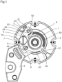
- the watchmaking device for the balance-spring 2,1 comprises a support 5 in the form of a cock, a stud holder 4 mounted directly or indirectly on the support 5, a base plate 6 and a stud 3 arranged to fix the outer end 1b of the balance spring 1 on the stud holder 4.
- the support 5 can be fixed or mobile as is the case for example for a tourbillon.
- the support 5 has the form of a cock or balance bridge and will be simply called cock in the following.
- the inner end 1a of the balance spring 1 is fixed by any suitable means to the arbor 20 of the balance 2.
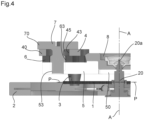
- the balance spring 1 generally extends in a plane PP ( Figure 4 ).
- the stud 3 is intended to be fixed in the stud holder 4 itself intended to be mounted on the cock 5.
- the cock 5 can be fixed to the movement in one or more positions, and it can also comprise height adjustment means, or even in a direction extending parallel to the balance shaft 20.
- the cock 5 carries a shock-absorbing bearing 8 in which a first end 20a of the balance shaft 20 is pivoted.
- the radial position of the stud holder 4 on the balance cock 5 relative to the central axis A-A of the balance spring 1 or the balance shaft 20 is finely adjustable.
- the stud holder 4 is constituted by a sliding plate 40 indirectly attached to the cock 5.
- the watch device further comprises a base plate 6.
- the sliding plate 40 and the base plate 6 are both semi-circular and arranged to be superimposed on the cock 5, the sliding plate 40 above the base plate 6, itself directly attached to the cock 5.
- the stud 3 is fixed to the stud holder 4 and in particular to the sliding plate 40 by any suitable means: for example, it is held in an opening 41 of said sliding plate 40 by means of a lateral screw 31.
- the cock 5 comprises a hole 50 intended to receive the shock-absorbing bearing 8 in which the balance shaft 20 is pivoted by its first end 20a.
- the base plate 6 here comprises an essentially circular or semi-circular portion 60 formed by two arms arranged, preferably, to surround the shock-absorbing bearing 8. In this way, the base plate 6 is held or fixed in translation on the cock 5, both in a plane essentially parallel to the cock 5 and along an axis essentially parallel to the axis A-A of the balance shaft 20.
- the sliding plate 40 is therefore intended to be placed above the base plate 6 attached to the balance-cock 5.
- This sliding plate 40 comprises a first radial guide opening 90 of oblong shape and arranged radially relative to the central axis AA of the balance spring 1 and to the balance shaft 20 in the service position of the sliding plate 40.
- This first radial guide opening 90 is intended to receive a pin 91 secured to the base plate 6 to guide the movement of the sliding plate 40.
- the first radial guide opening 90 is of oblong shape and closed to guarantee greater stability in the positioning of the stud holder 4.
- the first radial guide opening 90 and the pin 91 constitutes radial guide means for guiding the radial movement of the sliding plate 40 on the base plate 6 and on the balance-cock 5 relative to the central axis AA of the balance spring 1 in the service position of the device.
- the watch device comprises second radial guide means which, in the illustrated embodiment, have the form of a second radial guide opening 92 present on the base plate 6 and arranged to receive and cooperate with a radial guide surface 93 of the sliding plate 40.
- this radial guide surface 93 is the outer surface of an oblong portion 44 of the sliding plate 40 comprising the opening 41 receiving the stud 3.
- These second radial guide means 92, 93 also serve to ensure that the sliding plate 40 of the stud holder 4 is rotationally integral with the base plate 6 when the watch device is assembled. As illustrated in the figures, the first radial guide opening 90 in the sliding plate 40 is closed while the second radial guide opening 92 in the base plate 6 is open.
- the watchmaking device comprises means for fine radial adjustment of the radial position of the stud holder 4 on the balance cock 5 relative to the central axis AA of the balance spring 1 or the balance shaft 20.
- these adjustment means comprise an oblong opening 42 arranged on the sliding plate 40 radially relative to the central axis AA of the balance spring 1 and to the balance shaft 20 in the service position of the watchmaking device and an eccentric 9 arranged to pass through said oblong opening 42 and come to be fixed in the base plate 6.
- the eccentric 9 is driven into a hole 62 of the base plate 6 and passes through said hole 62, a recess 52 being provided in the cock 5 to serve as a clearance for the eccentric 9.
- the eccentric 9 cooperating with the oblong opening 42 of the sliding plate 40 and the hole 62 of the base plate 6 constitutes, in this embodiment, fine adjustment means allowing the displacement of the sliding plate 40 on the cock 5 for the fine adjustment of the radial position of said plate sliding 40 and stud 3 relative to the central axis AA of the balance spring 1 in the service position of the device.
- the sliding plate 40 further comprises a first curved segment 43 with an opening 45 intended to cooperate axially with a fixing screw 7 for fixing the sliding plate 40 on the cock 5.
- the fixing screw 7 passes through this opening 45 of the first curved segment 43 as well as an opening 65 in a corresponding second segment 63 on the base plate 6 and is screwed into a thread 53 provided for this purpose on the cock 5.
- this fixing screw 7 In an intermediate position of the fixing screw 7, its bearing surface 70 makes it possible to ensure the maintenance of the sliding plate 40 along an axis parallel to the central axis A-A of the balance spring 1 or to the balance shaft 20.
- this fixing screw 7 can be screwed into a locking position in which it makes the stud holder 4 and the base plate 6 integral with the balance cock 5. In its locking position, the fixing screw 7 also ensures the locking of the device, the stud holder 4 and the base plate 6 against possible angular displacement in the event of an accidental impact.
- the base plate 6 is placed on the balance-cock 5, its semi-circular portion 60 surrounding the shock-absorbing bearing 8 received in the hole 50.
- the driving of the shock-absorbing bearing 8 into the hole 50 of the balance-cock 5 ensures that the base plate 6 is held in a direction perpendicular to the plane of said base plate 6 or in a direction essentially parallel to the central axis A-A of the balance spring 1 or to the balance shaft 20.
- the arrangement of the shock-absorbing bearing 8 and the base plate 6 means that the latter can pivot on the balance-cock 5 around said shock-absorbing bearing 8 but is integral in translation with the balance-cock 5.
- the sliding plate 40 is then superimposed on the base plate 6 so that the pin 91 of the base plate 6 passes through the first radial guide opening 90 of the sliding plate 40 and the guide surface 93 of the sliding plate 40 cooperates with the second radial guide opening 92 of the base plate 6.
- the first and second segments 43, 63 and their respective openings 45, 65 are essentially superimposed.
- the sliding plate 40 and the base plate 6 are arranged so that, in their position superimposed on the cock 5, the sliding plate 40 is integral in rotation with the base plate 6 which can pivot around the shock-absorbing bearing 8 in order to allow the escapement to be aligned.
- this is possible by the cooperation of the pin 91 of the base plate 6 with the first radial guide opening 90 of the sliding plate 40 and by the cooperation between the radial guide surface 93 of the sliding plate 40 with the second radial guide opening 92 of the base plate 6.
- the eccentric 9 is driven through the oblong opening 42 of the sliding plate 40 into the hole 62 of the base plate 6, the recess 52 of the cock 5 avoiding any contact between the eccentric 9 and the cock 5.
- the fixing screw 7 is screwed through the openings 45, 65 of the first and second segments 43, 63 into its thread 53 on the cock 5 at least in its intermediate position.
- the balance wheel 2 is pivotally mounted by the first end 20a of its shaft 20 in the shock-absorbing bearing 8.
- the outer end 1b of the balance spring 1 must be inserted into the pin 3 fixed in the opening 41 of the pin holder 4 by means of the lateral screw 31 and then made integral with said pin 3 by gluing, pinning or any other suitable means.
- the fixing screw 7 can then be screwed into the cock 5 in its locking position to ensure that the sliding plate 40 and the base plate 6 are locked relative to each other and made integral with the cock 5.
- the displacement of the sliding plate 40 is limited by the size of the eccentric 9 and is guided by the radial guide means which are the pin 91 of the base plate 6 passing through the first radial guide opening 90 of the sliding plate 40 and the second radial guide opening 92 of the base plate 6 cooperating with the radial guide surface 93 of the sliding plate 40.
- the stud 3 and therefore the outer end 1b of the spiral 1 will thus move away from or move closer radially to the central axis AA of said spiral 1 or to the balance shaft 20.
- the fixing screw 7 is screwed back into the cock 5 in its locking position to ensure that the two plates are locked relative to each other and made integral with the cock 5.
- the device according to the present invention it is possible during the studding to introduce the outer end 1b of the hairspring 1 into the stud 3 without constraining the hairspring 1.
- the sliding plate 40 and therefore the stud 3 move radially relative to the central axis of the hairspring 1 which makes it possible to place the stud 3 in a position in which the outer end 1b of the hairspring can be introduced into the stud 3 without exerting any constraint on the hairspring 1.
- the presence of the base plate 6 makes it possible to carry out a rotational adjustment of the position of the stud 3 for a reference setting of the escapement associated with the 2-spiral balance regulator 1.
- This reference setting operation can be carried out independently of the radial adjustment of the position of the stud 3 described above.
- the fixing screw 7 is slightly unscrewed to allow the rotation (possibly with friction) of the base plate 6 on the cock 5 around the shock-absorbing bearing 8.
- the base plate 6 is then pivoted in one direction or the other, for example by pushing it by any suitable means (tweezers).
- the sliding plate 40 is integral in rotation with the base plate 6, it will follow the rotation imposed on the base plate 6 for the setting of the mark.
- the fixing screw 7 must be screwed back into the cock 5 to ensure the locking of the two plates relative to each other and make them integral with the cock 5.
- the first segment 43 of the sliding plate 40 and the corresponding second segment 63 of the base plate 6 and their respective opening 45, 65 are arranged to allow a rotation of the base plate 6/sliding plate 40 assembly of at most ⁇ 30° relative to a middle position and preferably, of at most ⁇ 13° around the shock-absorbing bearing 8.
- the pin 91 of the first radial guide means could be replaced by any similar projecting element.
- the pin could be carried by the sliding plate and the corresponding first radial guide opening by the base plate.
- the radial guide means may have other suitable shapes such as grooves present one in the sliding plate and the other in the base plate or the cock and arranged to cooperate with each other.
- the device comprises first and second radial guide means, but only one or the other of these means could suffice.
- the watch device for balance spring 2, 1 comprises a support 105 (which can be fixed or mobile), a stud holder 104 (consisting of a sliding plate 140) mounted on the support 105, a base plate 106, and a stud 103 arranged to fix the outer end 1b of the balance spring 1 on the stud holder 104.
- the support 105 which is preferably a balance cock or bridge, also carries the shock-absorbing bearing 8 which is mounted in a hole 150 of the support 105 which is surrounded by a collar 155.
- this bearing 8 is intended to receive one end of the shaft 20 of the balance 2 and ensures the maintenance in translation of the base plate 106 on the support 105, both in a plane essentially parallel to the support 105 and along an axis essentially parallel to the axis AA of the balance shaft 20.
- the stud holder 104 is integral in rotation with the base plate 106, and the latter comprises a portion 160 formed by two arms, which are preferably arranged to surround the shock-absorbing bearing 8, in order to allow rotational adjustment of the position of the stud 103 relative to the shaft 20 of the balance 2 to carry out the setting of an associated escapement.
- the radial position of the stud holder 104 on the support 105 relative to the central axis AA of the balance spring 1 or the balance shaft 20 is finely adjustable, but according to this second embodiment, the stud holder 104 is attached directly to the support 105 (preferably around the collar 155), and the base plate 106 is superimposed on the stud holder 104.
- the stud 103 can be fixed to the stud holder 104 and in particular to the sliding plate 140 forming said stud holder 104 by any suitable means: according to in this second embodiment, it is notably retained in an opening 141 of the sliding plate 140 by means of a lateral screw 131.
- the stud holder 104 and the base plate 106 have simpler and generally lighter shapes
- the watch device comprises radial and angular guide means which, as illustrated, comprise a guide opening 192 present on the base plate 106 which is arranged to receive and cooperate with a guide surface 193 of the sliding plate 140 of the stud holder 104.
- the guide surface 193 is the outer surface of an oblong portion 144 of the sliding plate 140 comprising the opening 141 receiving the stud 103.
- the watchmaking device comprises means for fine adjustment of the radial position of the stud holder 104 on the support 105 relative to the central axis A-A of the balance spring 1 or the balance shaft 20.
- these means comprise an oblong opening 142 arranged on the sliding plate 140 radially relative to the central axis A-A of the balance spring 1 and to the balance shaft 20 in the service position of the watchmaking device and an eccentric 109 arranged to pass through said oblong opening 142 and come to be fixed in the support 105 in its service position.
- the eccentric 109 is driven into a hole 152 of the support 105.
- the eccentric 109 cooperating with the oblong opening 142 of the sliding plate 140 allows the sliding plate 140 to be moved on the support 105 to carry out the fine adjustment of the radial position of said sliding plate 140 and of the stud 103 relative to the central axis A-A of the balance spring 1.
- the eccentric 109 fulfills a second function, more precisely, the fixing of the stud holder 104 on the support 105, and a separate fixing screw is then no longer necessary in this embodiment.
- the eccentric 109 comprises a head 109A ( figure 9 ) arranged to hold the plate 140 of the stud holder 104 high on the support 105, and the plate 140 can be mounted and guided centrally around the collar 155 as shown above.
- the stud holder 104 is mounted on the support 105 by driving the eccentric 109 into the hole 152, and subsequently the base plate 106 is mounted on the support 105 by driving the shock-absorbing bearing 8 into the hole 150 of the support 105.
- the watch device can subsequently receive the 2-spiral balance regulating member 1, by pivoting it by the first end 20a of its shaft 20 in the shock-absorbing bearing 8.
- the outer end 1b of the hairspring 1 is introduced into the stud 103 fixed in the opening 141 of the stud holder 104 by means of the lateral screw 131 and then this end is made integral with the stud 103 by gluing, pinning or any other suitable means.
- the alignment is carried out by adjusting the position of the base plate 106 in rotation around the shaft of the balance 20 which, in view of the guide means 192, 193, also adjusts the angular position of the stud holder 104 and therefore of the stud 103.
- this alignment operation is completely independent of a fine adjustment of the radial position of the stud holder 104.
- This fine radial adjustment is carried out as in the first embodiment by rotating the eccentric 109 in rotation, in one direction or the other, so that the sliding plate 140 moves relative to the base plate 106 and to the support 105 radially relative to the central axis AA of the balance spring 1.
- this radial displacement takes place in a plane essentially parallel to the plane PP of the balance 2 or of the balance spring 1 ( figure 8 ).
- the watch device according to the invention is arranged so that the stud can move radially by at most ⁇ 0.50 mm and even more advantageously by at most ⁇ 0.20 mm relative to a median radial position of the device.
- Such a range of radial movement may correspond, for example, to a rotation of the eccentric by 90° in each direction for one or other of the above embodiments.
- the use of the eccentric guarantees all the precision necessary for fine adjustment of the position of the stud holder and the stud.
- marks or graduations may be present on the eccentric 9, 109, on the plate 40, 140 of the stud holder 4, 104, and/or on the base plate 6, 106 to facilitate radial adjustment during an operation carried out manually or automatically using devices.
- the fine adjustment means for fine adjustment of the radial position of the stud holder relative to the central axis AA of the balance spring comprise an eccentric cooperating with an oblong opening in the sliding plate of the stud holder and fixed either in the base plate or directly in the support/cock.
- the eccentric may for example have a cam-shaped surface.
- other fine adjustment means could be envisaged such as a worm-type gear or an element bearing on a cam that can be moved for adjustment.
- Said adjustment means may be distributed indifferently between the sliding plate and the base plate and/or the support/cock to allow radial movement of the sliding plate relative to the support/cock.
- the hairspring 1 can be made of any suitable material, metallic or not.
- the present invention applies in particular to a hairspring made of silicon or another material without plastic deformation.
- the stud 3 can have any suitable shape, appropriate to the characteristics of the hairspring.
- the device according to the invention can comprise a metal hairspring whose terminal curve is bent.
- balance springs made of silicon or other similar materials there may be significant variability in the radius of the terminal curves of the balance springs of the same manufacturing batch. Even if the elastic torque of these balance springs is generally not affected by a difference in the radius of their terminal curve - the active length and the section remaining the same - it has been observed that the regulating organs equipped with these balance springs nevertheless have a difference in isochronism.
- the present invention allows the introduction of a radial prestress at the stud which has an impact on the isochronism of the balance-spring assembly and therefore on chronometry. This effect is verified in particular for balance springs made of silicon or similar material without deformation but also for metal balance springs.
- the watchmaking device allowing the fine adjustment of the radial position of the stud holder can be used to compensate for the variabilities in the radius of the terminal curve of the balance spring which could affect the isochronism. Furthermore, as indicated above, the device also allows the studding of the outer end of a hairspring without exerting unwanted stress on the hairspring thanks to the possible adjustment of the radial position of the stud relative to the central axis of the hairspring.
- the present invention relates to a watchmaking device comprising, for a balance-spring regulating organ comprising a fixed or mobile support, a stud holder mounted directly or indirectly on the support and a stud arranged to fix the outer end of the balance spring on the stud holder, the support carrying a shock-absorbing bearing intended to receive one end of a balance shaft.
- the watchmaking device comprises fixing means for fixing the stud holder on the support and also a base plate comprising a portion formed by two arms allowing rotational adjustment of the position of the stud relative to the balance shaft for setting the reference of an escapement associated with the regulating organ, the stud holder being integral in rotation with the base plate.
- the watchmaking device comprises fine radial adjustment means allowing fine and precise adjustment of the radial position of the stud relative to the central axis of the balance spring by moving the stud holder relative to the support and the base plate in a radial direction relative to the central axis of the balance spring.
- the radial position of the stud and the outer end of the hairspring relative to the central axis of the hairspring can be adjusted with precision and accuracy. This allows in particular to precisely control the isochronism of the regulating organ comprising the hairspring. It is notably possible to compensate for a variation in the radius of the terminal curve of the hairspring relative to the theoretical curve - variation due for example to the manufacturing process - and which could impact the isochronism and the rate of the regulating organ comprising the hairspring.
- the movement of the stud holder is done in a plane essentially parallel to the plane of the hairspring so as not to affect the flatness of said hairspring.
- the device comprises first radial guide means ensuring the guidance of the stud holder in its movements relative to the support in a radial direction relative to the axis of the balance spring.
- second radial guide means are also provided. These guide means are preferably provided on the stud holder and on the base plate, which makes the radial guidance independent of the support.
- the radial guide means can also ensure angular guidance between the stud holder and the base plate so that the two rotate together around the balance shaft.
- the fine radial adjustment means comprise an eccentric passing through an opening in the stud holder and driven into the support or an intermediate part secured to the support or vice versa.
- the eccentric in fact allows a very precise adjustment in an easy manner.
- Other equally practical and precise adjustment methods are possible, such as a worm gear or an element supported by a moving cam.
- the support is the balance bridge or the balance cock and even more preferably, it is fixed in the watch movement.
- the support could be formed by another element of the frame, movable or fixed, intended to be mounted in a watch movement of any kind as well as, in a suitable form, in tourbillon or carousel cages.
Landscapes
- Physics & Mathematics (AREA)
- General Physics & Mathematics (AREA)
- Springs (AREA)
Applications Claiming Priority (1)
| Application Number | Priority Date | Filing Date | Title |
|---|---|---|---|
| CH000989/2023A CH721117A1 (fr) | 2023-09-11 | 2023-09-11 | Dispositif horloger permettant de régler la position radiale du piton |
Publications (1)
| Publication Number | Publication Date |
|---|---|
| EP4521173A1 true EP4521173A1 (de) | 2025-03-12 |
Family
ID=88207274
Family Applications (1)
| Application Number | Title | Priority Date | Filing Date |
|---|---|---|---|
| EP24199467.2A Pending EP4521173A1 (de) | 2023-09-11 | 2024-09-10 | Uhrvorrichtung |
Country Status (2)
| Country | Link |
|---|---|
| EP (1) | EP4521173A1 (de) |
| CH (1) | CH721117A1 (de) |
Citations (9)
| Publication number | Priority date | Publication date | Assignee | Title |
|---|---|---|---|---|
| CH131856A (fr) * | 1927-12-21 | 1929-03-15 | Tavannes Watch Co Sa | Coq de mouvement d'horlogerie. |
| CH344372A (fr) * | 1959-01-14 | 1960-01-31 | Isorac S A | Dispositif de réglage du ressort spiral d'un balancier |
| CH350926A (fr) * | 1958-05-17 | 1960-12-15 | Isorac S A | Dispositif de réglage du ressort spiral d'un balancier |
| FR1460220A (fr) | 1965-02-04 | 1966-11-25 | Dispositif de fixation d'un spiral d'horlogerie à son piton | |
| EP1918791A1 (de) | 2006-11-03 | 2008-05-07 | Lange Uhren GmbH | Rückerloses Schwingsystem für eine Uhr |
| CH707742A2 (fr) | 2013-03-12 | 2014-09-15 | Seiko Instr Inc | Système balancier-spiral, mouvement de pièce d'horlogerie et pièce d'horlogerie. |
| EP3081996A1 (de) | 2015-04-16 | 2016-10-19 | Montres Breguet S.A. | Spirale aus mikrobearbeitbarem material mit isochronismus-korrektur |
| CH714809A2 (fr) | 2018-03-20 | 2019-09-30 | Montres Breguet Sa | Pièce d'horlogerie équipée d'un dispositif de réglage de l'ébat d'un mobile tournant. |
| CH717088A2 (fr) | 2020-01-29 | 2021-07-30 | Seiko Watch Kk | Mécanisme de réglage de spiral, unité de pont de balancier, mouvement et pièce d'horlogerie. |
-
2023
- 2023-09-11 CH CH000989/2023A patent/CH721117A1/fr unknown
-
2024
- 2024-09-10 EP EP24199467.2A patent/EP4521173A1/de active Pending
Patent Citations (9)
| Publication number | Priority date | Publication date | Assignee | Title |
|---|---|---|---|---|
| CH131856A (fr) * | 1927-12-21 | 1929-03-15 | Tavannes Watch Co Sa | Coq de mouvement d'horlogerie. |
| CH350926A (fr) * | 1958-05-17 | 1960-12-15 | Isorac S A | Dispositif de réglage du ressort spiral d'un balancier |
| CH344372A (fr) * | 1959-01-14 | 1960-01-31 | Isorac S A | Dispositif de réglage du ressort spiral d'un balancier |
| FR1460220A (fr) | 1965-02-04 | 1966-11-25 | Dispositif de fixation d'un spiral d'horlogerie à son piton | |
| EP1918791A1 (de) | 2006-11-03 | 2008-05-07 | Lange Uhren GmbH | Rückerloses Schwingsystem für eine Uhr |
| CH707742A2 (fr) | 2013-03-12 | 2014-09-15 | Seiko Instr Inc | Système balancier-spiral, mouvement de pièce d'horlogerie et pièce d'horlogerie. |
| EP3081996A1 (de) | 2015-04-16 | 2016-10-19 | Montres Breguet S.A. | Spirale aus mikrobearbeitbarem material mit isochronismus-korrektur |
| CH714809A2 (fr) | 2018-03-20 | 2019-09-30 | Montres Breguet Sa | Pièce d'horlogerie équipée d'un dispositif de réglage de l'ébat d'un mobile tournant. |
| CH717088A2 (fr) | 2020-01-29 | 2021-07-30 | Seiko Watch Kk | Mécanisme de réglage de spiral, unité de pont de balancier, mouvement et pièce d'horlogerie. |
Also Published As
| Publication number | Publication date |
|---|---|
| CH721117A1 (fr) | 2025-03-31 |
Similar Documents
| Publication | Publication Date | Title |
|---|---|---|
| EP3502788B1 (de) | Vorrichtung zur selbstregulierung der aktiven länge einer spirale | |
| EP2887154A1 (de) | Befestigungsmechanismus eines Spiralklötzchen an eine Unruhbrücke, und Reguliervorrichtung mit Unruh-Spiralfeder, die einen solchen Mechanismus umfasst | |
| EP4286962B1 (de) | Regulierorgan für uhr, das eine rückervorrichtung umfasst, die mit verriegelungsmitteln ausgestattet ist | |
| EP3839651A1 (de) | Mechanischer oszillator einer uhr mit flexibler führung | |
| EP3792700A1 (de) | Oszillator einer uhr mit flexiblem zapfen | |
| EP4099101B1 (de) | Vorrichtung zum einbau eines uhr-oszillators | |
| EP4428627B1 (de) | Vorrichtung zur autonomen einstellung der aktiven länge einer spiralfeder | |
| EP4286961A1 (de) | Uhrregulierungsorgan mit einer präzisionsrückervorrichtung | |
| EP4521173A1 (de) | Uhrvorrichtung | |
| EP4432020A1 (de) | Uhrwerk | |
| EP4492157A1 (de) | Verfahren zur einstellung des isochronismus eines spiral-unruh-reglers | |
| EP4428628B1 (de) | Vorrichtung zur autonomen einstellung der aktiven länge einer spiralfeder | |
| CH720948A1 (fr) | Procédé de réglage de l'isochronisme d'un organe régulateur de type balancier-spiral | |
| EP4428626B1 (de) | Vorrichtung zur autonomen einstellung der aktiven länge einer spiralfeder | |
| EP4428624B1 (de) | Vorrichtung zur autonomen einstellung der aktiven länge einer spiralfeder | |
| CH720580A2 (fr) | Dispositif de réglage autonome de la longueur active d'un spiral | |
| CH720583A2 (fr) | Dispositif de réglage autonome de la longueur active d'un spiral | |
| CH720584A2 (fr) | Dispositif de réglage autonome de la longueur active d'un spiral | |
| EP4575668A1 (de) | Uhranordnung für ein regulierorgan mit mitteln zur gangeinstellung | |
| EP4498175A1 (de) | Uhreinstellorgan mit hakenbetätigungssystem | |
| WO2024141601A1 (fr) | Système réglant pour mouvement horloger | |
| WO2024141600A1 (fr) | Système réglant pour mouvement horloger | |
| CH720978A2 (fr) | Système d'actionnement micromécanique à guidage flexible pour l'horlogerie | |
| CH721430A2 (fr) | Ensemble d'horlogerie pour organe réglant muni de moyens d'ajustement de la marche | |
| EP4498178A1 (de) | Mikromechanisches betätigungssystem mit flexibler führung für die uhr |
Legal Events
| Date | Code | Title | Description |
|---|---|---|---|
| PUAI | Public reference made under article 153(3) epc to a published international application that has entered the european phase |
Free format text: ORIGINAL CODE: 0009012 |
|
| STAA | Information on the status of an ep patent application or granted ep patent |
Free format text: STATUS: THE APPLICATION HAS BEEN PUBLISHED |
|
| AK | Designated contracting states |
Kind code of ref document: A1 Designated state(s): AL AT BE BG CH CY CZ DE DK EE ES FI FR GB GR HR HU IE IS IT LI LT LU LV MC ME MK MT NL NO PL PT RO RS SE SI SK SM TR |
|
| STAA | Information on the status of an ep patent application or granted ep patent |
Free format text: STATUS: REQUEST FOR EXAMINATION WAS MADE |
|
| 17P | Request for examination filed |
Effective date: 20250901 |