EP4550001A2 - Leistungssteuerung einer drahtlosen verfolgungsvorrichtung mit eingeschränkter stromquelle - Google Patents
Leistungssteuerung einer drahtlosen verfolgungsvorrichtung mit eingeschränkter stromquelle Download PDFInfo
- Publication number
- EP4550001A2 EP4550001A2 EP25165188.1A EP25165188A EP4550001A2 EP 4550001 A2 EP4550001 A2 EP 4550001A2 EP 25165188 A EP25165188 A EP 25165188A EP 4550001 A2 EP4550001 A2 EP 4550001A2
- Authority
- EP
- European Patent Office
- Prior art keywords
- tracking device
- wireless tracking
- wireless
- sensor
- active mode
- Prior art date
- Legal status (The legal status is an assumption and is not a legal conclusion. Google has not performed a legal analysis and makes no representation as to the accuracy of the status listed.)
- Pending
Links
Images

Classifications
-
- G—PHYSICS
- G01—MEASURING; TESTING
- G01S—RADIO DIRECTION-FINDING; RADIO NAVIGATION; DETERMINING DISTANCE OR VELOCITY BY USE OF RADIO WAVES; LOCATING OR PRESENCE-DETECTING BY USE OF THE REFLECTION OR RERADIATION OF RADIO WAVES; ANALOGOUS ARRANGEMENTS USING OTHER WAVES
- G01S19/00—Satellite radio beacon positioning systems; Determining position, velocity or attitude using signals transmitted by such systems
- G01S19/01—Satellite radio beacon positioning systems transmitting time-stamped messages, e.g. GPS [Global Positioning System], GLONASS [Global Orbiting Navigation Satellite System] or GALILEO
- G01S19/13—Receivers
- G01S19/34—Power consumption
-
- Y—GENERAL TAGGING OF NEW TECHNOLOGICAL DEVELOPMENTS; GENERAL TAGGING OF CROSS-SECTIONAL TECHNOLOGIES SPANNING OVER SEVERAL SECTIONS OF THE IPC; TECHNICAL SUBJECTS COVERED BY FORMER USPC CROSS-REFERENCE ART COLLECTIONS [XRACs] AND DIGESTS
- Y02—TECHNOLOGIES OR APPLICATIONS FOR MITIGATION OR ADAPTATION AGAINST CLIMATE CHANGE
- Y02D—CLIMATE CHANGE MITIGATION TECHNOLOGIES IN INFORMATION AND COMMUNICATION TECHNOLOGIES [ICT], I.E. INFORMATION AND COMMUNICATION TECHNOLOGIES AIMING AT THE REDUCTION OF THEIR OWN ENERGY USE
- Y02D30/00—Reducing energy consumption in communication networks
- Y02D30/70—Reducing energy consumption in communication networks in wireless communication networks
Definitions
- This invention relates to managing operations of a wireless tracking device with a restricted power source, more specifically to operating the wireless tracking device in more than one mode of operation to reduce power consumption and prolong its operational time.
- Wireless tracking devices are employed to track locations and conditions of various assets. Such wireless tracking devices are often mounted on the assets or placed in the vicinity of the assets. As the assets are transported or are exposed to changing environment, the wireless tracking devices detect the location and/or sense changing conditions of the assets. Then, the wireless tracking devices send wireless messages indicating the locations and/or other environment parameters of the assets to a remote monitoring station. Based on the collected information, the remote monitoring station may prompt actions such as sending reports to customers, taking remedial actions to prevent deterioration of the assets, and initiating retrieval of stolen assets.
- a wireless tracking device includes various components and sensors enclosed in a casing.
- the casing provides robust protection against dirt or other contaminants as well as external forces.
- the wireless tracking device may include various components such as temperature sensors, humidity sensors, light sensors, accelerometers, gyroscopes, magnetometers, controllers, GPS modules and wireless communication modules. These components or modules may consume power during their operations.
- Some wireless tracking devices include sensors to accommodate diverse applications whereas other wireless tracking devices are equipped with fewer types of sensors selected for specific applications.
- a wireless tracking device To provide power to these components and modules, a wireless tracking device includes a restricted power source such as batteries or solar cells. In many cases, the wireless tracking devices operate in environments where access to other power sources is unavailable. The wireless tracking devices often rely on the restricted power source for their operations. Hence, to increase the operable time of a wireless tracking device, it is necessary to reduce the power consumption of its components.
- a restricted power source such as batteries or solar cells.
- Embodiments relate to a wireless tracking device that operates in at least two modes of operation to reduce power consumption.
- a hibernation mode the wireless tracking device turns off the components consuming a large amount of power to preserve power.
- the wireless tracking device is intermittently placed in an active mode where components consuming a large amount of power are turned on.
- the wireless tracking device switches from the hibernation mode to the active mode to track locations or detect changes in its environment.
- the wireless tracking device may revert back to the hibernation mode if no further events are detected or a preset time is elapsed.
- the components turned off in the hibernation mode include a locating device for determining the location of the wireless tracking device and a communication module for sending the message over a wireless network.
- the locating device and the communication module consume a large amount of power, and hence, these components are intermittently operated in the active mode to preserve power.
- the wireless tracking device includes two controllers. One controller consumes less power than the other controller. The controller consuming less power remains turned on in both the active mode and the hibernation mode. In contrast, the controller consuming more power is turned on selectively during the active mode to control components that consume a large amount of power.
- a geofence is established for an area having poor connectivity to the wireless network.
- the wireless tracking module determines proximity to the geofence, and switches to the active mode at a higher frequency to detect whether the wireless tracking module has entered the geofence and to send updated messages before the wireless tracking device enters the geofence.
- Embodiments described herein provide a wireless tracking device operating in at least two modes to reduce power consumption and extend the operable time of the wireless tracking device.
- the wireless tracking device activates a communication module for communicating with a remote device via wireless connection or other components that consume a large amount of power.
- a hibernation mode the components or modules in the wireless tracking device are shut down to reduce power consumption.
- the wireless tracking device may switch from the hibernation mode to the active mode selectively when a predetermine event is detected.
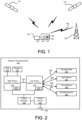
- FIG. 1 is a diagram illustrating a wireless tracking device 122 in a moving vehicle 120.
- the wireless tracking device 122 may be located in a cargo 126 being transported by the vehicle 120.
- the wireless tracking device 122 tracks its location using a Global Positioning System (GPS) module that detects signals from satellites 110.
- GPS Global Positioning System
- the wireless tracking device 122 inside cargoes 126 also communicates with a remote monitoring station 128 over a wireless communication channel 130.
- GPS Global Positioning System
- the vehicle 120 may carry multiple units of cargoes 126 where each unit is equipped with a wireless tracking device 122. Each cargo 126 may be destined to a different target location. As a cargo 126 is transported, a wireless tracking device 122 attached to the cargo 126 tracks the location of the cargo 126 and environmental conditions surrounding the cargo 126. Then, the location and other environment information are transmitted to a remote monitoring station 128 in a wireless message.
- the environment conditions detected by the wireless tracking device 122 may include, but are not limited to, temperature, humidity, light, sound, vibration, tilt, shock, certain types of chemical compounds, pressure, magnetic field, smoke, and movements.
- the wireless tracking device 122 may be configured to detect some or all of these environment conditions.
- wireless tracking device 122 is not limited to moving cargoes 126.
- the wireless tracking device 122 may be used for an object that remains stationary. In such case, the wireless tracking device 122 is used primarily for detecting environmental conditions surrounding the wireless tracking device 122.
- the vehicle 120 is merely an example of a mode of transport.
- the wireless tracking device 122 and the cargo 126 may be transported using other modes of transport such as vessels, trains or airplanes.
- Cargo 126 may be any asset transported in commerce, including among other things, envelopes, parcels, express packages, boxes, palettes, containers, crates, and specialty goods and materials.
- the wireless tracking device 122 operates in two distinct modes: an active mode and a hibernation mode.
- the active mode most or all of the components in the wireless tracking device 122 are activated.
- the activated components include high power consumption components such as a wireless communication module.
- the hibernation mode a fewer number of components or modules in the wireless tracking device 122 are activated. Other components or modules are turned off to preserve power.
- the wireless tracking device 122 switches between the active mode and the hibernation mode in response to detecting or in anticipation of an event.
- FIG. 2 is a block diagram illustrating the wireless tracking device 122, according to one embodiment.
- the wireless tracking device 122 may include, among other components, a high power system controller 210, a low power system controller 214, a Global Positioning System (GPS) module 222, a wireless communication module 226, a power manager 230, a restricted power source 234, and various sensors 250 through 262.
- the wireless tracking device 122 may include other components not illustrated in Figure 2 such as an input module or speakers.
- the wireless tracking device 122 of Figure 2 has a dual processor structure including two controllers: the high power system controller 210 and the low power system controller 214. By using the two controllers, the power consumption may be reduced in the hibernation mode while obtaining high computing capacity during the active mode.
- the high power system controller 210 becomes active and performs power intensive operations. Such power intensive operations include, for example, determining the location of the wireless tracking device 122 using the GPS module 222 and communicating wirelessly with the remote monitoring station 128 via the wireless communication module 226.
- the wireless tracking device 122, the GPS module 222 and the wireless communication module 226 may be disabled to reduce power consumption.
- the low power system controller 214 is embodied as ATMEGA 8-bit microcontroller (available from Atmel Corporation of San Jose, California), Energy Micro Gecko micro controller (available from Energy Micro AS of Oslo, Norway) or SAM3 (available from Atmel Corporation of San Jose, California).
- Examples of the high power system controllers 210 include the Marvell PXA series, ARM11, Cortex-A series, or TI DSPs.
- the high power system controller 210 controls the operation of the GPS module 222 and the wireless communication module 226.
- the GPS module 222 and the wireless communication module 226 are also deactivated to reduce power consumption.
- the low power system controller 214 remains active in both the active mode and the hibernation mode.
- the low power system controller 214 determines whether to place the wireless tracking device 122 in the active mode or the hibernation mode, as described below in detail with reference to Figure 3 .
- the low power system controller 214 is connected to low-power consumption components such as sensors 250 through 262.
- the low power system controller 214 continues to receive sensor signals 282 through 294 even in the hibernation mode to avoid losing meaningful sensor data. However, the sampling rate and the sensitivity of the sensor signals 282 through 294 may be reduced in the hibernation mode to reduce power consumption.
- the low power system controller 214 sends commands to the power manager 230 to turn on or off power provided to the high power system controller 210.
- the power manager 230 turns off power to the high power system controller 210.
- the power manager 230 is connected to the power source 234.
- the power source 234 may be a restricted power source such as a battery or solar cells.
- the power source 234 includes a charge circuit.
- the charger circuit receives charging electric current via port 238 to charge the battery.
- the GPS module 222 may include an antenna and a signal processing unit for receiving GPS signals.
- the GPS module 222 operates under the command of the high power system controller 210 to identify the current location of the wireless tracking device 122.
- the GPS module 222 embodies A-GPS (Assisted GPS) which improves the startup performance or TTFF (Time To First Fix) by utilizing data received via the wireless communication module 226.
- A-GPS Assisted GPS
- TTFF Time To First Fix
- the wireless communication module 226 includes a transceiver for sending or receiving data to or from the remote monitoring station 128.
- the wireless communication module 226 may establish communicating using various communication protocols such as GSM, WiFi, Bluetooth, Zigbee, UMTS/HSxPA, 3GPP Long Term Evolution (LTE) and WiMAX.
- the sensors 250 through 262 detect various physical properties or conditions and send the sensor signals 282 through 294 to the low power system controller 214.
- the sensors in the wireless tracking device 122 include, for example, an accelerometer 250, a light sensor 254, a temperature sensor 258 and a humidity sensor 262.
- the wireless tracking device 122 may include other types of sensors to detect different physical properties or conditions.
- the high power system controller 210 and the low power system controller 214 communicate over a data bridge 212.
- the high power system controller 210 may receive the sensor data from the low power system controller 214, compiles the sensor data into a message, and sends the message to the remote monitoring station 128 via the wireless communication module 226.
- the low power system controller 214 receives location information (based on the GPS module 222) from the high power system controller 210 or any data (e.g., control commands) received from the remote monitoring station 128 via the data bridge 212.
- the high power system controller 210 and the low power system controller 214 include computer readable storage medium 270 and computer readable storage medium 272, respectively.
- the computer readable storage medium 270 stores instructions for execution by the high power system controller 210.
- the computer readable storage medium 272 stores instructions for execution by the low power system controller 214.
- the computer readable storage media 270, 272 are embodied as a non-volatile memory device (e.g., EEPROM (Electrically Erasable Programmable Read-Only Memory) or a flash memory), a volatile memory device (e.g., Random Access Memory (RAM)) or a combination of both.
- EEPROM Electrically Erasable Programmable Read-Only Memory
- RAM Random Access Memory
- FIG. 2 The embodiment of Figure 2 is merely illustrative. Wireless tracking devices of different configuration may also be used.
- a single processor architecture including only a single controller may be used.
- the single processor architecture all the components and sensors are connected and controlled by the single controller.
- the single controller may operate in two modes: an active mode with a higher processing capacity, and a hibernation mode with reduced power consumption.
- the high power system controller 210 and the low power system controller 214 could also be implemented in a multi core configuration or via virtualization with a single core.
- Figure 3 is a diagram illustrating a method of placing the wireless tracking device 122 in the active mode or the hibernation mode, according to one embodiment.
- the low power system controller 214 receives 310 the sensor signals 282 through 294 from the sensors 250 through 262 or the location of the wireless tracking device 122 from the GPS module 222. For this purpose, the low power system controller 214 stores instructions for switching power modes in the computer readable storage medium 272.
- the low power system controller 214 determines 312 if one or more of predetermined events are detected to place the wireless tracking device 122 in the active mode.
- Various types of events may be used for switching the modes.
- the wireless tracking device 122 is placed in the active mode when events of interest to a user are likely to occur or continue whereas the wireless tracking device 122 is placed in the hibernation mode when the events of interest are unlikely to occur or continue.
- the low power system controller 214 places or maintains 314 the wireless tracking device 122 in the active mode.
- the predetermined events include detection of movement of the wireless tracking device 122 by the accelerometer sensor or the speed of the wireless tracking device 122 above a threshold. While the wireless tracking device 122 is in the active mode, the low power system controller 214 may monitor changes in the location based on GPS signals from the current active mode session to determine the speed of the wireless tracking device 122. Alternatively, the low power system controller 214 may compare the location of the wireless tracking device 122 with the location of the wireless tracking device 122 in the previous active mode session to determine the speed of the wireless tracking device 122.
- the wireless tracking device 122 is placed or maintained 314 in the active mode when external events are detected via the sensors 250 through 262.
- the external events refer to events occurring outside the wireless tracking device 122 and may include, for example, (i) a motion of the wireless tracking device 122 (as detected by the accelerometer 250), (ii) changes from indoor to outdoor or vice versa (as detected by the light sensor 254), (iii) changes in temperature (as detected by the temperature sensor 258), (iv) changes in the humidity (as detected by the humidity sensor 262), and (v) detection of certain chemical compounds or smoke. If such external events are detected, events of interest are likely to ensue or continue. Hence, the wireless tracking device 122 is maintained in the active mode to capture data associated with the external events.
- the event may be passing of time or a signal from a timer indicating a predetermined time.
- the low power system controller 214 may periodically switch the wireless tracking device 122 to the active mode.
- the low power system controller 214 switches to the active mode more often or stays in the active mode for a longer time when the accelerometer 250 sends a signal 282 indicating the movement of the wireless tracking device 122.
- the wireless tracking device 122 is more likely to experience significant changes in the environment when the wireless tracking device 122 is being transported. Hence, the wireless tracking device 122 is placed in the active mode to send more frequent updates to the remote monitoring station 128.
- the low power system controller 214 may switch back to the hibernation mode if a certain amount of time is elapsed.
- the low power system controller 214 places or maintains 318 the wireless tracking device 122 in the hibernation mode.
- the wireless tracking device 122 is unlikely to encounter significant changes when predetermined events are not detected. Hence, the low power system controller 214 places the wireless tracking device 122 in the hibernation mode to preserve power.
- the process After placing or maintaining 314, 318 the wireless tracking device 122 in the active mode or the hibernation mode, the process returns to receiving 310 the sensor signals or locations.
- more significant events in the sensor signals or more drastic changes in locations are needed to switch the wireless tracking device 122 from the hibernation mode to the active mode compared to the events for maintaining the wireless tracking device 122 in the active mode.
- the sensitivity of sensors e.g., the accelerometer 250
- the sensitivity of sensors is lowered in the hibernation mode to avoid the wireless tracking device 122 from waking up to the active mode due to minor variances in the sensor signals.
- the wireless tracking device 122 may be prevented from waking up due to insignificant events while retaining the chance of detecting significant events.
- the wireless tracking device 122 may move through a geographic region where wireless communication is not available or where reception of the wireless communication is poor.
- geographic region may be established as a goefence in which the wireless tracking device 122 does not attempt to communicate with the remote monitoring station 128.
- a geofence herein refers to a geographical area artificially defined for one purpose or the other. By avoiding communication in the geofenced area, power consumption associated with attempting to communicate with the remote monitoring station 128 in a poor reception area can be avoided. In addition, this feature may be used to satisfy certain regulatory requirements about RF transmissions in particular areas.
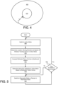
- FIG 4 is a diagram illustrating a geofence 410 associated with wireless communication of the wireless tracking device 122 where wireless communication is unavailable or the signal reception is poor.
- the wireless tracking device 122 does not attempt to communicate with the remote monitoring station 128.
- Data collected for events while the wireless tracking device 122 remains in the geofence 410 are stored and then transmitted to the remote monitoring station 128 when the wireless tracking device 122 leaves the geofence 410.
- region 420 represents an area where the wireless communication of the wireless tracking device 122 is available with good reception.
- the wireless tracking device 122 moves from point X to point Z. While the wireless tracking device 122 is in the region 420 and distanced away from the geofence 410 (represented by line X-Y), the wireless tracking device 122 switches to the active mode at a first frequency (i.e. sampling interval). As the wireless tracking device 122 approaches the geofence 410 (represented by line Y-Z), the wireless tracking device 122 switches to the active mode at a second frequency higher than the first frequency (i.e., the wireless tracking device 122 is placed in the active mode more often). For example, the wireless tracking device 122 may switch from the hibernation mode to the active mode every 10 minutes when the wireless tracking device 122 is traveling from point X to point Y. The same wireless tracking device 122 may switch from the hibernation mode to the active mode every 5 minutes when the wireless tracking device 122 is traveling from point Y to point Z.
- a first frequency i.e. sampling interval
- the wireless tracking device 122 switches to the active mode at a second frequency higher than the
- the wireless tracking device 122 gradually switches to active mode with increasing frequency or stays in the active mode for a longer time as the wireless tracking device 122 approaches the geofence 410.
- FIG. 5 is a flowchart illustrating the process of switching between the active mode and the hibernation mode when the geofence 410 is implemented.
- the wireless tracking device 122 switches 508 to the active mode.
- the low power system controller 214 determines 510 the location, the moving direction and the speed of the wireless tracking device 122. Based on the location, the moving direction and the speed of the wireless tracking device 122, the wireless tracking device 122 computes 514 the estimated time that the wireless tracking device 122 will arrive at the region of the geofence 410.
- the wireless tracking device 122 can continue to update the remote monitoring station with wireless messages without using excessive amount of power.
Landscapes
- Engineering & Computer Science (AREA)
- Radar, Positioning & Navigation (AREA)
- Remote Sensing (AREA)
- Computer Networks & Wireless Communication (AREA)
- Physics & Mathematics (AREA)
- General Physics & Mathematics (AREA)
- Mobile Radio Communication Systems (AREA)
- Telephone Function (AREA)
- Position Fixing By Use Of Radio Waves (AREA)
- Lock And Its Accessories (AREA)
Applications Claiming Priority (4)
| Application Number | Priority Date | Filing Date | Title |
|---|---|---|---|
| US12/980,171 US9696429B2 (en) | 2010-12-28 | 2010-12-28 | Power management in wireless tracking device operating with restricted power source |
| EP21150806.4A EP3828596B1 (de) | 2010-12-28 | 2011-10-18 | Leistungssteuerung einer drahtlosen verfolgungsvorrichtung mit eingeschränkter stromquelle |
| EP11852911.4A EP2659467B1 (de) | 2010-12-28 | 2011-10-18 | Leistungssteuerung einer drahtlosen verfolgungsvorrichtung mit eingeschränkter stromquelle |
| PCT/US2011/056784 WO2012091785A1 (en) | 2010-12-28 | 2011-10-18 | Power management in wireless tracking device operating with restricted power source |
Related Parent Applications (2)
| Application Number | Title | Priority Date | Filing Date |
|---|---|---|---|
| EP11852911.4A Division EP2659467B1 (de) | 2010-12-28 | 2011-10-18 | Leistungssteuerung einer drahtlosen verfolgungsvorrichtung mit eingeschränkter stromquelle |
| EP21150806.4A Division EP3828596B1 (de) | 2010-12-28 | 2011-10-18 | Leistungssteuerung einer drahtlosen verfolgungsvorrichtung mit eingeschränkter stromquelle |
Publications (2)
| Publication Number | Publication Date |
|---|---|
| EP4550001A2 true EP4550001A2 (de) | 2025-05-07 |
| EP4550001A3 EP4550001A3 (de) | 2025-07-30 |
Family
ID=46315965
Family Applications (3)
| Application Number | Title | Priority Date | Filing Date |
|---|---|---|---|
| EP11852911.4A Active EP2659467B1 (de) | 2010-12-28 | 2011-10-18 | Leistungssteuerung einer drahtlosen verfolgungsvorrichtung mit eingeschränkter stromquelle |
| EP21150806.4A Active EP3828596B1 (de) | 2010-12-28 | 2011-10-18 | Leistungssteuerung einer drahtlosen verfolgungsvorrichtung mit eingeschränkter stromquelle |
| EP25165188.1A Pending EP4550001A3 (de) | 2010-12-28 | 2011-10-18 | Leistungssteuerung einer drahtlosen verfolgungsvorrichtung mit eingeschränkter stromquelle |
Family Applications Before (2)
| Application Number | Title | Priority Date | Filing Date |
|---|---|---|---|
| EP11852911.4A Active EP2659467B1 (de) | 2010-12-28 | 2011-10-18 | Leistungssteuerung einer drahtlosen verfolgungsvorrichtung mit eingeschränkter stromquelle |
| EP21150806.4A Active EP3828596B1 (de) | 2010-12-28 | 2011-10-18 | Leistungssteuerung einer drahtlosen verfolgungsvorrichtung mit eingeschränkter stromquelle |
Country Status (7)
| Country | Link |
|---|---|
| US (6) | US9696429B2 (de) |
| EP (3) | EP2659467B1 (de) |
| CN (1) | CN103380446B (de) |
| DE (1) | DE112011104622B4 (de) |
| ES (2) | ES3026608T3 (de) |
| GB (1) | GB2501626B (de) |
| WO (1) | WO2012091785A1 (de) |
Families Citing this family (59)
| Publication number | Priority date | Publication date | Assignee | Title |
|---|---|---|---|---|
| US10488174B2 (en) * | 2018-03-06 | 2019-11-26 | General Electric Company | Systems and methods for wearable voltage detection devices |
| JP2012526309A (ja) | 2009-05-08 | 2012-10-25 | ピーター ウィルドン,マイケル | 識別装置、識別システムおよび識別方法 |
| KR101710666B1 (ko) * | 2012-12-12 | 2017-02-27 | 한국전자통신연구원 | 무선 네트워크 기반 복합 사면 감시 장치 및 방법 |
| IN2013CH00215A (de) * | 2013-01-16 | 2015-07-31 | Accenture Global Services Ltd | |
| KR102048273B1 (ko) | 2013-02-22 | 2019-11-25 | 삼성전자주식회사 | 이동통신시스템에서의 위치 등록장치 및 방법 |
| US9341479B2 (en) | 2013-03-05 | 2016-05-17 | Google Inc. | Configurable point of interest alerts |
| US9055475B2 (en) * | 2013-03-15 | 2015-06-09 | Qualcomm Incorporated | Power optimizations for challenging WAN service conditions |
| WO2014163540A1 (en) | 2013-04-02 | 2014-10-09 | Telefonaktiebolaget L M Ericsson (Publ) | Message server and communication terminal |
| US10845452B2 (en) | 2013-05-08 | 2020-11-24 | Cm Hk Limited | Hybrid positioning method, electronic apparatus and computer-readable recording medium thereof |
| US20140368313A1 (en) * | 2013-06-14 | 2014-12-18 | Texas Instruments Incorporated | Vehicle keyfob with accelerometer to extend battery life |
| US8755824B1 (en) | 2013-06-28 | 2014-06-17 | Google Inc. | Clustering geofence-based alerts for mobile devices |
| US9712960B2 (en) * | 2013-06-28 | 2017-07-18 | Intel Corporation | Geofencing |
| US11076113B2 (en) | 2013-09-26 | 2021-07-27 | Rosemount Inc. | Industrial process diagnostics using infrared thermal sensing |
| US10823592B2 (en) | 2013-09-26 | 2020-11-03 | Rosemount Inc. | Process device with process variable measurement using image capture device |
| US10638093B2 (en) | 2013-09-26 | 2020-04-28 | Rosemount Inc. | Wireless industrial process field device with imaging |
| US9516860B2 (en) * | 2013-10-04 | 2016-12-13 | Thrive Solutions Ltd. | Animal monitoring system and method |
| US9986375B2 (en) | 2014-02-12 | 2018-05-29 | Google Llc | Energy-efficient location determination |
| US10067237B1 (en) * | 2014-03-12 | 2018-09-04 | Marvell International Ltd. | Method and apparatus for geo-fence detection |
| US9857228B2 (en) | 2014-03-25 | 2018-01-02 | Rosemount Inc. | Process conduit anomaly detection using thermal imaging |
| US9488527B2 (en) | 2014-03-25 | 2016-11-08 | Rosemount Inc. | Process temperature measurement using infrared detector |
| US9521519B2 (en) * | 2014-07-02 | 2016-12-13 | Mediatek Inc. | Mobile communication devices and context-based geofence control methods thereof |
| US10171934B2 (en) * | 2014-08-29 | 2019-01-01 | Ebay Inc. | Efficient geo-fence data transfer and notifications using a time to reach value |
| US10914635B2 (en) | 2014-09-29 | 2021-02-09 | Rosemount Inc. | Wireless industrial process monitor |
| JP6554295B2 (ja) * | 2015-03-16 | 2019-07-31 | 古野電気株式会社 | 観測データ送信装置、観測システム、および、観測データ送信方法 |
| US9775095B2 (en) | 2015-06-18 | 2017-09-26 | Carrier Corporation | Aircraft proximity sensor system for radio frequency transmission device |
| KR102427822B1 (ko) * | 2015-08-12 | 2022-08-01 | 삼성전자주식회사 | 위치 정보 제공 방법 및 장치 |
| JP6559038B2 (ja) * | 2015-10-15 | 2019-08-14 | キヤノン株式会社 | 通信装置、その制御方法、及びプログラム |
| JP2017156257A (ja) * | 2016-03-03 | 2017-09-07 | Necプラットフォームズ株式会社 | 無線通信装置、位置情報通知システム、および位置情報通知方法、並びにコンピュータ・プログラム |
| US10623249B2 (en) * | 2016-05-09 | 2020-04-14 | Tile, Inc. | Dynamic tracking device reconfiguration |
| US10102492B1 (en) * | 2016-07-17 | 2018-10-16 | Marquette Trishaun | Smart asset tracking tag system and method |
| US10408489B1 (en) * | 2016-07-17 | 2019-09-10 | Marquette Trishaun | Smart system monitor and method |
| CN107643531A (zh) * | 2016-07-20 | 2018-01-30 | 西安中兴新软件有限责任公司 | Gps控制方法及装置 |
| CN106218673B (zh) * | 2016-08-31 | 2017-10-27 | 交控科技股份有限公司 | 一种基于空天车地一体化网络的列车运行控制系统 |
| US10902310B2 (en) | 2016-12-14 | 2021-01-26 | Trackonomy Systems, Inc. | Wireless communications and transducer based event detection platform |
| JP6784204B2 (ja) * | 2017-03-22 | 2020-11-11 | カシオ計算機株式会社 | 情報処理装置、情報処理方法及びプログラム |
| US10244481B2 (en) * | 2017-04-05 | 2019-03-26 | Biosense Webster (Israel) Ltd. | System and method for switching on wireless tool only when the location frequencies are detected |
| US11715361B2 (en) * | 2017-04-12 | 2023-08-01 | WAVE Systems, Inc. | Systems and methods for potential drowning incident detection |
| US10495764B2 (en) * | 2018-01-30 | 2019-12-03 | Bastian Solutions, Llc | Asset tracking system |
| US12105206B2 (en) | 2018-04-16 | 2024-10-01 | Pinpoint Ideas, LLC | GPS tracking device with extended battery life |
| US20190317223A1 (en) | 2018-04-16 | 2019-10-17 | Pinpoint Ideas, LLC | GPS Tracking Device with Extended Battery Life |
| US10356577B1 (en) * | 2018-07-20 | 2019-07-16 | Blackberry Limited | Method and system for asset tracking |
| US11619747B2 (en) * | 2018-11-04 | 2023-04-04 | Chenyu Wang | Location monitoring apparatuses configured for low-power operation |
| US11368925B2 (en) * | 2019-04-18 | 2022-06-21 | Battle Sight Technologies, LLC | Tracking device |
| US11889460B2 (en) * | 2019-10-23 | 2024-01-30 | Briggs & Stratton, Llc | Equipment tracking system |
| SE544126C2 (en) * | 2019-12-06 | 2022-01-04 | Jop Connected Ab | Tracker device |
| CN111148041A (zh) * | 2019-12-28 | 2020-05-12 | 高树安弗(杭州)科技有限公司 | 一种低功耗位置监视装置、系统及方法 |
| US20230300561A1 (en) * | 2020-08-10 | 2023-09-21 | Katch Ip Pty Limited | Tracking device and system |
| US12047841B2 (en) | 2020-09-21 | 2024-07-23 | Trackonomy Systems, Inc. | Detecting special events and strategically important areas in an IoT tracking system |
| EP4205053A4 (de) | 2020-10-03 | 2024-09-18 | Trackonomy Systems, Inc. | System und verfahren zur erzeugung von umweltprofilen zur bestimmung der logistik von vermögenswerten |
| EP4002245A1 (de) * | 2020-11-24 | 2022-05-25 | Carrier Corporation | Verfahren und system zum automatischen starten und anhalten einer überwachungsvorrichtung |
| US20240041064A1 (en) * | 2020-12-31 | 2024-02-08 | Umaro Foods, Inc. | Protein concentrate and method of preparation |
| US12222209B2 (en) * | 2021-02-26 | 2025-02-11 | Here Global B.V. | Method, apparatus, and system for shipment tracking |
| US12330810B2 (en) * | 2021-03-09 | 2025-06-17 | Carrier Corporation | System and apparatus for detecting restrained unit load device using floor latch sensor |
| EP4068735B1 (de) | 2021-03-29 | 2024-05-29 | Sony Group Corporation | Betrieb einer elektronischen vorrichtung während des transports |
| WO2022221345A1 (en) * | 2021-04-12 | 2022-10-20 | Trackonomy Systems, Inc. | Method and system for automatic power management of portable internet of things devices |
| EP4102422B1 (de) * | 2021-06-07 | 2024-05-22 | Sony Network Communications Europe B.V. | Positionsbestimmung in einer elektronischen vorrichtung während des transports |
| WO2024102042A1 (en) * | 2022-11-09 | 2024-05-16 | Telefonaktiebolaget Lm Ericsson (Publ) | Controlling a device to sense an environment around the device |
| US12032748B1 (en) * | 2023-11-14 | 2024-07-09 | Geotab Inc. | Devices and methods for activating an asset tracker |
| US20250252743A1 (en) * | 2024-02-02 | 2025-08-07 | Toyota Motor Engineering & Manufacturing North America, Inc. | Standby mode for monitoring vehicle surroundings |
Family Cites Families (46)
| Publication number | Priority date | Publication date | Assignee | Title |
|---|---|---|---|---|
| US5592173A (en) | 1994-07-18 | 1997-01-07 | Trimble Navigation, Ltd | GPS receiver having a low power standby mode |
| US7253731B2 (en) | 2001-01-23 | 2007-08-07 | Raymond Anthony Joao | Apparatus and method for providing shipment information |
| CN1282357C (zh) * | 1997-01-27 | 2006-10-25 | 富士写真胶片株式会社 | 记录全球定位系统装置的测位信息的摄像机 |
| US6492904B2 (en) | 1999-09-27 | 2002-12-10 | Time Domain Corporation | Method and system for coordinating timing among ultrawideband transmissions |
| US6353390B1 (en) * | 1999-12-31 | 2002-03-05 | Jeffrey Beri | Method and system of configuring a boundary and tracking an object thereby |
| US7212829B1 (en) | 2000-02-28 | 2007-05-01 | Chung Lau | Method and system for providing shipment tracking and notifications |
| US6339397B1 (en) | 2000-06-01 | 2002-01-15 | Lat-Lon, Llc | Portable self-contained tracking unit and GPS tracking system |
| US6847892B2 (en) | 2001-10-29 | 2005-01-25 | Digital Angel Corporation | System for localizing and sensing objects and providing alerts |
| BR0107583A (pt) | 2000-10-27 | 2002-12-31 | Digital Angel Corp | Sistemas e métodos de monitoramento e rastreamento |
| US7010073B2 (en) * | 2001-01-19 | 2006-03-07 | Qualcomm, Incorporated | Delay lock loops for wireless communication systems |
| WO2002095438A2 (en) * | 2001-05-22 | 2002-11-28 | Geospatial Technologies, Inc. | A durable global asset-tracking device and a method of using the same |
| DE10140517A1 (de) * | 2001-08-17 | 2003-02-27 | Philips Corp Intellectual Pty | Schaltungsanordnung zur Steuerung eines Sensors |
| US7184745B2 (en) | 2003-02-03 | 2007-02-27 | Motorola, Inc. | Wireless receiver operation |
| US20040192352A1 (en) | 2003-03-25 | 2004-09-30 | Nokia Corporation | Energy efficient object location reporting system |
| FI117029B (fi) | 2005-03-02 | 2006-05-15 | Tracker Oy | Menetelmä, laite, laitejärjestely ja tietokoneohjelmatuote liikkuvan kohteen seuraamiseksi |
| AT502346B1 (de) | 2005-09-08 | 2008-12-15 | Tarter Philipp Dipl Ing | Ortungsgerät |
| US7616124B2 (en) * | 2005-10-11 | 2009-11-10 | Snif Labs, Inc. | Tag system |
| US20080246656A1 (en) | 2006-04-25 | 2008-10-09 | Ghazarian Ohanes D | Automatic GPS tracking system with passive battery circuitry |
| CN101075752A (zh) | 2006-05-19 | 2007-11-21 | 上海航天卫星应用有限公司 | 光伏电站卫星远程监控系统 |
| GB0616282D0 (en) * | 2006-08-16 | 2006-09-27 | Circuitree Ltd | Context Monitoring For Remote Sensor Platform |
| US20080086391A1 (en) | 2006-10-05 | 2008-04-10 | Kurt Maynard | Impromptu asset tracking |
| US7521348B2 (en) * | 2006-10-23 | 2009-04-21 | Samsung Electronics Co., Ltd. | Method of fabricating semiconductor device having fine contact holes |
| US7739060B2 (en) | 2006-12-22 | 2010-06-15 | Accuri Cytometers, Inc. | Detection system and user interface for a flow cytometer system |
| US8121609B2 (en) * | 2006-12-28 | 2012-02-21 | Worldscout Corporation | System and method for determining the location of a location tracking device |
| JP2008171298A (ja) * | 2007-01-15 | 2008-07-24 | Fujifilm Corp | 診療スケジュール管理装置及び方法 |
| JP4471389B2 (ja) * | 2007-01-22 | 2010-06-02 | トレックス・セミコンダクター株式会社 | デュアル加速度センサシステム |
| US7925900B2 (en) * | 2007-01-26 | 2011-04-12 | Microsoft Corporation | I/O co-processor coupled hybrid computing device |
| CN101019761A (zh) | 2007-03-20 | 2007-08-22 | 中国人民解放军军事医学科学院卫生装备研究所 | 可穿戴式低负荷生理监护系统 |
| US8497774B2 (en) * | 2007-04-05 | 2013-07-30 | Location Based Technologies Inc. | Apparatus and method for adjusting refresh rate of location coordinates of a tracking device |
| KR20100030613A (ko) | 2007-07-09 | 2010-03-18 | 소니 가부시끼가이샤 | 전자 기기 및 그 제어 방법 |
| US9322923B2 (en) | 2007-09-04 | 2016-04-26 | Mediatek Inc. | Method of switching electronic apparatus between different modes according to connection status of wireless connection and electronic apparatus thereof |
| CN101470182B (zh) | 2007-12-24 | 2013-07-03 | 卡特彼勒公司 | 一种省电的管理移动实体通讯的系统和方法 |
| US8620393B2 (en) | 2008-06-13 | 2013-12-31 | Qualcomm Incorporated | Optimizing battery life and network resources during position location tracking scenario |
| US8254868B2 (en) * | 2009-03-11 | 2012-08-28 | Enfora, Inc. | Methods and apparatus for modeling, monitoring, estimating and controlling power consumption in battery-operated devices |
| US7898471B2 (en) | 2009-04-27 | 2011-03-01 | GTA Electronics Co., Ltd. | Power-saving position tracking device |
| US8477011B2 (en) * | 2009-05-08 | 2013-07-02 | Icontrol, Inc. | mLOCK device and associated methods |
| US20110018707A1 (en) | 2009-07-27 | 2011-01-27 | Dobson Eric L | Shipping container having integral geoclock system |
| MX2012002088A (es) * | 2009-08-17 | 2012-04-10 | Deal Magic Inc | Monitoreo contextualmente alerta de activos. |
| US8314704B2 (en) | 2009-08-28 | 2012-11-20 | Deal Magic, Inc. | Asset tracking using alternative sources of position fix data |
| US20110054979A1 (en) | 2009-08-31 | 2011-03-03 | Savi Networks Llc | Physical Event Management During Asset Tracking |
| US8239169B2 (en) * | 2009-09-25 | 2012-08-07 | Gregory Timothy L | Portable computing device and method for asset management in a logistics system |
| US8555355B2 (en) | 2010-12-07 | 2013-10-08 | Verizon Patent And Licensing Inc. | Mobile pin pad |
| US9049663B2 (en) * | 2010-12-10 | 2015-06-02 | Qualcomm Incorporated | Processing involving multiple sensors |
| US8989053B1 (en) | 2013-11-29 | 2015-03-24 | Fedex Corporate Services, Inc. | Association management in a wireless node network |
| US10438162B2 (en) | 2014-03-12 | 2019-10-08 | Roambee Corporation | Systems, methods, and devices for tracking a shipment using a wireless tracker |
| US10990922B1 (en) | 2019-02-02 | 2021-04-27 | Roambee Corporation | Continuous inventory management |
-
2010
- 2010-12-28 US US12/980,171 patent/US9696429B2/en active Active
-
2011
- 2011-10-18 EP EP11852911.4A patent/EP2659467B1/de active Active
- 2011-10-18 ES ES21150806T patent/ES3026608T3/es active Active
- 2011-10-18 GB GB1311126.5A patent/GB2501626B/en active Active
- 2011-10-18 EP EP21150806.4A patent/EP3828596B1/de active Active
- 2011-10-18 ES ES11852911T patent/ES2865729T3/es active Active
- 2011-10-18 DE DE112011104622.7T patent/DE112011104622B4/de active Active
- 2011-10-18 WO PCT/US2011/056784 patent/WO2012091785A1/en not_active Ceased
- 2011-10-18 CN CN201180066689.2A patent/CN103380446B/zh active Active
- 2011-10-18 EP EP25165188.1A patent/EP4550001A3/de active Pending
-
2017
- 2017-06-01 US US15/610,791 patent/US10061033B2/en active Active
-
2018
- 2018-08-01 US US16/051,865 patent/US10488526B2/en active Active
-
2019
- 2019-10-25 US US16/664,536 patent/US10782416B2/en active Active
-
2020
- 2020-08-18 US US16/996,815 patent/US11487019B2/en active Active
-
2021
- 2021-05-06 US US17/313,439 patent/US11796684B2/en active Active
Also Published As
| Publication number | Publication date |
|---|---|
| ES3026608T3 (en) | 2025-06-11 |
| US9696429B2 (en) | 2017-07-04 |
| US20120161958A1 (en) | 2012-06-28 |
| US10061033B2 (en) | 2018-08-28 |
| US11796684B2 (en) | 2023-10-24 |
| DE112011104622B4 (de) | 2025-02-20 |
| EP3828596B1 (de) | 2025-03-26 |
| CN103380446B (zh) | 2018-03-13 |
| EP3828596A1 (de) | 2021-06-02 |
| US10782416B2 (en) | 2020-09-22 |
| US20200379125A1 (en) | 2020-12-03 |
| GB2501626A (en) | 2013-10-30 |
| US11487019B2 (en) | 2022-11-01 |
| WO2012091785A1 (en) | 2012-07-05 |
| EP2659467A4 (de) | 2014-12-31 |
| CN103380446A (zh) | 2013-10-30 |
| GB201311126D0 (en) | 2013-08-07 |
| DE112011104622T5 (de) | 2014-01-02 |
| US20170269220A1 (en) | 2017-09-21 |
| US20200057164A1 (en) | 2020-02-20 |
| US20210255334A1 (en) | 2021-08-19 |
| GB2501626B (en) | 2015-09-02 |
| US10488526B2 (en) | 2019-11-26 |
| EP2659467A1 (de) | 2013-11-06 |
| EP4550001A3 (de) | 2025-07-30 |
| EP2659467B1 (de) | 2021-02-24 |
| US20190064366A1 (en) | 2019-02-28 |
| ES2865729T3 (es) | 2021-10-15 |
Similar Documents
| Publication | Publication Date | Title |
|---|---|---|
| US11796684B2 (en) | Power management in wireless tracking device operating with restricted power source | |
| US10142790B2 (en) | Conservation of battery life in GPS accessing portable devices | |
| US11089546B2 (en) | Inventory tracking tags, system and method for prolonging battery life | |
| US9794942B1 (en) | System and method for saving energy in a locator apparatus | |
| US20150011249A1 (en) | Mobile device location determination using wi-fi signals | |
| EP2629174A2 (de) | Verfahren zur Verringerung des Stromverbrauchs innerhalb einer tragbaren Kommunikationsvorrichtung | |
| CN106855630A (zh) | 一种基于电子地图的低功耗集装箱定位装置及方法 | |
| CN112995907A (zh) | 一种监控系统、监控方法、存储介质和电子设备 | |
| EP3669140B1 (de) | Aktualisierung einer vorrichtungsposition entsprechend des kurses und der bewegung | |
| EP3191863B1 (de) | Verfahren und vorrichtung zur ortung von verbrauchszählerendpunkten | |
| JP2009538807A (ja) | 貨物専用コンテナの状態を監視するための監視装置及び方法 | |
| US20150276932A1 (en) | Apparatus and method for determining location of mobile object | |
| HK40054459A (en) | Power management in wireless tracking device operating with restricted power source | |
| HK40054459B (en) | Power management in wireless tracking device operating with restricted power source | |
| US20140278225A1 (en) | Determining changes in physical location based on the observed magnetic field | |
| KR20260070532A (ko) | 태양광 구동 전자 디바이스에서의 전력 관리 | |
| CN111148041A (zh) | 一种低功耗位置监视装置、系统及方法 |
Legal Events
| Date | Code | Title | Description |
|---|---|---|---|
| PUAI | Public reference made under article 153(3) epc to a published international application that has entered the european phase |
Free format text: ORIGINAL CODE: 0009012 |
|
| STAA | Information on the status of an ep patent application or granted ep patent |
Free format text: STATUS: THE APPLICATION HAS BEEN PUBLISHED |
|
| AC | Divisional application: reference to earlier application |
Ref document number: 2659467 Country of ref document: EP Kind code of ref document: P Ref document number: 3828596 Country of ref document: EP Kind code of ref document: P |
|
| AK | Designated contracting states |
Kind code of ref document: A2 Designated state(s): AL AT BE BG CH CY CZ DE DK EE ES FI FR GB GR HR HU IE IS IT LI LT LU LV MC MK MT NL NO PL PT RO RS SE SI SK SM TR |
|
| RAP1 | Party data changed (applicant data changed or rights of an application transferred) |
Owner name: FEDERAL EXPRESS CORPORATION |
|
| PUAL | Search report despatched |
Free format text: ORIGINAL CODE: 0009013 |
|
| AK | Designated contracting states |
Kind code of ref document: A3 Designated state(s): AL AT BE BG CH CY CZ DE DK EE ES FI FR GB GR HR HU IE IS IT LI LT LU LV MC MK MT NL NO PL PT RO RS SE SI SK SM TR |
|
| RIC1 | Information provided on ipc code assigned before grant |
Ipc: G01S 19/34 20100101AFI20250623BHEP |
|
| STAA | Information on the status of an ep patent application or granted ep patent |
Free format text: STATUS: REQUEST FOR EXAMINATION WAS MADE |
|
| 17P | Request for examination filed |
Effective date: 20260120 |