EP4545875A1 - Gefriergerät - Google Patents
Gefriergerät Download PDFInfo
- Publication number
- EP4545875A1 EP4545875A1 EP23827109.2A EP23827109A EP4545875A1 EP 4545875 A1 EP4545875 A1 EP 4545875A1 EP 23827109 A EP23827109 A EP 23827109A EP 4545875 A1 EP4545875 A1 EP 4545875A1
- Authority
- EP
- European Patent Office
- Prior art keywords
- working medium
- heat exchanger
- indoor
- piping
- outdoor
- Prior art date
- Legal status (The legal status is an assumption and is not a legal conclusion. Google has not performed a legal analysis and makes no representation as to the accuracy of the status listed.)
- Pending
Links
Images

Classifications
-
- F—MECHANICAL ENGINEERING; LIGHTING; HEATING; WEAPONS; BLASTING
- F25—REFRIGERATION OR COOLING; COMBINED HEATING AND REFRIGERATION SYSTEMS; HEAT PUMP SYSTEMS; MANUFACTURE OR STORAGE OF ICE; LIQUEFACTION SOLIDIFICATION OF GASES
- F25B—REFRIGERATION MACHINES, PLANTS OR SYSTEMS; COMBINED HEATING AND REFRIGERATION SYSTEMS; HEAT PUMP SYSTEMS
- F25B13/00—Compression machines, plants or systems, with reversible cycle
-
- F—MECHANICAL ENGINEERING; LIGHTING; HEATING; WEAPONS; BLASTING
- F25—REFRIGERATION OR COOLING; COMBINED HEATING AND REFRIGERATION SYSTEMS; HEAT PUMP SYSTEMS; MANUFACTURE OR STORAGE OF ICE; LIQUEFACTION SOLIDIFICATION OF GASES
- F25B—REFRIGERATION MACHINES, PLANTS OR SYSTEMS; COMBINED HEATING AND REFRIGERATION SYSTEMS; HEAT PUMP SYSTEMS
- F25B9/00—Compression machines, plants or systems, in which the refrigerant is air or other gas of low boiling point
- F25B9/10—Compression machines, plants or systems, in which the refrigerant is air or other gas of low boiling point with several cooling stages
-
- F—MECHANICAL ENGINEERING; LIGHTING; HEATING; WEAPONS; BLASTING
- F25—REFRIGERATION OR COOLING; COMBINED HEATING AND REFRIGERATION SYSTEMS; HEAT PUMP SYSTEMS; MANUFACTURE OR STORAGE OF ICE; LIQUEFACTION SOLIDIFICATION OF GASES
- F25B—REFRIGERATION MACHINES, PLANTS OR SYSTEMS; COMBINED HEATING AND REFRIGERATION SYSTEMS; HEAT PUMP SYSTEMS
- F25B25/00—Machines, plants or systems, using a combination of modes of operation covered by two or more of the groups F25B1/00 - F25B23/00
- F25B25/005—Machines, plants or systems, using a combination of modes of operation covered by two or more of the groups F25B1/00 - F25B23/00 using primary and secondary systems
-
- F—MECHANICAL ENGINEERING; LIGHTING; HEATING; WEAPONS; BLASTING
- F25—REFRIGERATION OR COOLING; COMBINED HEATING AND REFRIGERATION SYSTEMS; HEAT PUMP SYSTEMS; MANUFACTURE OR STORAGE OF ICE; LIQUEFACTION SOLIDIFICATION OF GASES
- F25B—REFRIGERATION MACHINES, PLANTS OR SYSTEMS; COMBINED HEATING AND REFRIGERATION SYSTEMS; HEAT PUMP SYSTEMS
- F25B49/00—Arrangement or mounting of control or safety devices
- F25B49/02—Arrangement or mounting of control or safety devices for compression type machines, plants or systems
-
- F—MECHANICAL ENGINEERING; LIGHTING; HEATING; WEAPONS; BLASTING
- F25—REFRIGERATION OR COOLING; COMBINED HEATING AND REFRIGERATION SYSTEMS; HEAT PUMP SYSTEMS; MANUFACTURE OR STORAGE OF ICE; LIQUEFACTION SOLIDIFICATION OF GASES
- F25B—REFRIGERATION MACHINES, PLANTS OR SYSTEMS; COMBINED HEATING AND REFRIGERATION SYSTEMS; HEAT PUMP SYSTEMS
- F25B9/00—Compression machines, plants or systems, in which the refrigerant is air or other gas of low boiling point
- F25B9/002—Compression machines, plants or systems, in which the refrigerant is air or other gas of low boiling point characterised by the refrigerant
- F25B9/006—Compression machines, plants or systems, in which the refrigerant is air or other gas of low boiling point characterised by the refrigerant the refrigerant containing more than one component
-
- F—MECHANICAL ENGINEERING; LIGHTING; HEATING; WEAPONS; BLASTING
- F25—REFRIGERATION OR COOLING; COMBINED HEATING AND REFRIGERATION SYSTEMS; HEAT PUMP SYSTEMS; MANUFACTURE OR STORAGE OF ICE; LIQUEFACTION SOLIDIFICATION OF GASES
- F25B—REFRIGERATION MACHINES, PLANTS OR SYSTEMS; COMBINED HEATING AND REFRIGERATION SYSTEMS; HEAT PUMP SYSTEMS
- F25B2313/00—Compression machines, plants or systems with reversible cycle not otherwise provided for
- F25B2313/003—Indoor unit with water as a heat sink or heat source
-
- F—MECHANICAL ENGINEERING; LIGHTING; HEATING; WEAPONS; BLASTING
- F25—REFRIGERATION OR COOLING; COMBINED HEATING AND REFRIGERATION SYSTEMS; HEAT PUMP SYSTEMS; MANUFACTURE OR STORAGE OF ICE; LIQUEFACTION SOLIDIFICATION OF GASES
- F25B—REFRIGERATION MACHINES, PLANTS OR SYSTEMS; COMBINED HEATING AND REFRIGERATION SYSTEMS; HEAT PUMP SYSTEMS
- F25B2400/00—General features or devices for refrigeration machines, plants or systems, combined heating and refrigeration systems or heat-pump systems, i.e. not limited to a particular subgroup of F25B
- F25B2400/04—Refrigeration circuit bypassing means
- F25B2400/0403—Refrigeration circuit bypassing means for the condenser
-
- F—MECHANICAL ENGINEERING; LIGHTING; HEATING; WEAPONS; BLASTING
- F25—REFRIGERATION OR COOLING; COMBINED HEATING AND REFRIGERATION SYSTEMS; HEAT PUMP SYSTEMS; MANUFACTURE OR STORAGE OF ICE; LIQUEFACTION SOLIDIFICATION OF GASES
- F25B—REFRIGERATION MACHINES, PLANTS OR SYSTEMS; COMBINED HEATING AND REFRIGERATION SYSTEMS; HEAT PUMP SYSTEMS
- F25B2400/00—General features or devices for refrigeration machines, plants or systems, combined heating and refrigeration systems or heat-pump systems, i.e. not limited to a particular subgroup of F25B
- F25B2400/04—Refrigeration circuit bypassing means
- F25B2400/0409—Refrigeration circuit bypassing means for the evaporator
-
- F—MECHANICAL ENGINEERING; LIGHTING; HEATING; WEAPONS; BLASTING
- F25—REFRIGERATION OR COOLING; COMBINED HEATING AND REFRIGERATION SYSTEMS; HEAT PUMP SYSTEMS; MANUFACTURE OR STORAGE OF ICE; LIQUEFACTION SOLIDIFICATION OF GASES
- F25B—REFRIGERATION MACHINES, PLANTS OR SYSTEMS; COMBINED HEATING AND REFRIGERATION SYSTEMS; HEAT PUMP SYSTEMS
- F25B2600/00—Control issues
- F25B2600/25—Control of valves
- F25B2600/2501—Bypass valves
-
- F—MECHANICAL ENGINEERING; LIGHTING; HEATING; WEAPONS; BLASTING
- F25—REFRIGERATION OR COOLING; COMBINED HEATING AND REFRIGERATION SYSTEMS; HEAT PUMP SYSTEMS; MANUFACTURE OR STORAGE OF ICE; LIQUEFACTION SOLIDIFICATION OF GASES
- F25B—REFRIGERATION MACHINES, PLANTS OR SYSTEMS; COMBINED HEATING AND REFRIGERATION SYSTEMS; HEAT PUMP SYSTEMS
- F25B2600/00—Control issues
- F25B2600/25—Control of valves
- F25B2600/2519—On-off valves
-
- F—MECHANICAL ENGINEERING; LIGHTING; HEATING; WEAPONS; BLASTING
- F25—REFRIGERATION OR COOLING; COMBINED HEATING AND REFRIGERATION SYSTEMS; HEAT PUMP SYSTEMS; MANUFACTURE OR STORAGE OF ICE; LIQUEFACTION SOLIDIFICATION OF GASES
- F25B—REFRIGERATION MACHINES, PLANTS OR SYSTEMS; COMBINED HEATING AND REFRIGERATION SYSTEMS; HEAT PUMP SYSTEMS
- F25B2700/00—Sensing or detecting of parameters; Sensors therefor
- F25B2700/21—Temperatures
- F25B2700/2115—Temperatures of a compressor or the drive means therefor
- F25B2700/21152—Temperatures of a compressor or the drive means therefor at the discharge side of the compressor
Definitions
- the present invention relates to a refrigeration apparatus using a refrigeration cycle working medium containing a fluoroolefin and particularly relates to a refrigeration apparatus that can successfully avoid the impact of disproportionation of a fluoroolefin.
- a refrigeration cycle working medium is usually composed of a refrigerant and a refrigerating machine oil (lubricating oil retained in a hermetic compressor).
- HCFCs hydrofluorocarbons
- ODP ozone depletion potential
- a typical example is difluoromethane (HFC-32 or R-32).
- HFCs have stability when used as refrigeration cycle working media, they have a long atmospheric lifetime and therefore a high global warming potential (GWP).
- GWP global warming potential
- fluoroolefins having a lower GWP than HFCs in particular the use of hydrofluoroolefins (HFOs)
- HFO-1123 1,1,2-trifluoroethylene
- R-32 which is currently in widespread use.
- Patent Literature 1 An example of a previously proposed refrigeration apparatus using a fluoroolefin such as HFO-1123 is disclosed in Patent Literature 1.
- the refrigeration apparatus disclosed in Patent Literature 1 includes a dual cycle made up of a heat source-side heat medium circuit and a load-side heat medium circuit, and at least one of a heat source-side heat medium and a load-side heat medium which are used in the circuits is a refrigerant containing HFO-1123.
- the heat source-side heat medium circuit includes a cascade heat exchanger that effects heat exchange between the heat source-side and load-side heat media.
- the heat source-side heat medium circuit is located in an outdoor space, and a load-side heat exchanger included in the load-side heat medium circuit is located in an indoor space.
- the cascade heat exchanger included in the heat source-side heat medium circuit is located in the outdoor space.
- fluoroolefins have a low GWP means that they have a short atmospheric lifetime. In other words, fluoroolefins are easily chemically decomposed and have low stability.
- a fluoroolefin such as HFO-1123 is known to easily undergo a self-polymerization reaction called a disproportionation reaction (hereinafter referred to as "disproportionation").
- disproportionation is often induced, for example, by high pressure or generated heat during the use of a refrigeration cycle working medium. Additionally, the occurrence of disproportionation entails a large amount of heat release, and a chain reaction of disproportionation is known to occur. Such disproportionation results in a large amount of soot, which could reduce the reliability of the refrigeration cycle system.
- either or both of the working media (heat source-side and load-side heat media) used in the heat source-side and load-side heat medium circuits of the dual cycle may contain HFO-1123.
- Patent Literature 1 gives no consideration to the occurrence of disproportionation of a fluoroolefin such as HFO-1123 or the impact of disproportionation on the heat source-side and load-side heat medium circuits.
- the present invention has been made to solve the problem as described above, and an object of the present invention is to provide a refrigeration apparatus using a fluoroolefin as a working medium and including a dual cycle made up of an indoor-side circuit and an outdoor-side circuit, the refrigeration apparatus being adapted to, in the event of disproportionation of the fluoroolefin, successfully avoid the possibility that the disproportionation has an impact on indoor equipment.
- a refrigeration apparatus includes: a first heat exchanger; a second heat exchanger; a compressor; and an expansion mechanism, wherein the first heat exchanger, the compressor, and the expansion mechanism are located in an outdoor space and connected to first piping that allows a first working medium to circulate through the first heat exchanger, the compressor, and the expansion mechanism, the first heat exchanger, the compressor, the expansion mechanism, and the first piping constituting an outdoor-side circuit, the second heat exchanger is located in an indoor space and connected to second piping that allows a second working medium to circulate through the second heat exchanger, the second heat exchanger and the second piping constituting an indoor-side circuit, the refrigeration apparatus further includes a secondary heat exchanger located between the first piping and the second piping to effect heat exchange between the first working medium and the second working medium, the secondary heat exchanger is located in the outdoor space, the first working medium contains at least a fluoroolefin, and the second working medium contains no fluoroolefin.
- any fluoroolefin which can undergo disproportionation is not used as the second working medium circulating in the indoor-side circuit, while a fluoroolefin is used as the first working medium circulating in the outdoor-side circuit.
- the secondary heat exchanger which enables heat exchange between the indoor-side circuit and the outdoor-side circuit is located in the outdoor space.
- the present invention can provide a refrigeration apparatus configured as described above which uses a fluoroolefin as a working medium and includes a dual cycle made up of an indoor-side circuit and an outdoor-side circuit, the refrigeration apparatus being adapted to, in the event of disproportionation of the fluoroolefin, successfully avoid the possibility that the disproportionation has an impact on the indoor equipment.
- a refrigeration apparatus includes: a first heat exchanger; a second heat exchanger; a compressor; and an expansion mechanism, wherein the first heat exchanger, the compressor, and the expansion mechanism are located in an outdoor space and connected to first piping that allows a first working medium to circulate through the first heat exchanger, the compressor, and the expansion mechanism, the first heat exchanger, the compressor, the expansion mechanism, and the first piping constituting an outdoor-side circuit, the second heat exchanger is located in an indoor space and connected to second piping that allows a second working medium to circulate through the second heat exchanger, the second heat exchanger and the second piping constituting an indoor-side circuit, the refrigeration apparatus further includes a secondary heat exchanger located between the first piping and the second piping to effect heat exchange between the first working medium and the second working medium, the secondary heat exchanger is located in the outdoor space, the first working medium contains at least a fluoroolefin, and the second working medium contains no fluoroolefin.
- any fluoroolefin which can undergo disproportionation is not used as the second working medium circulating in the indoor-side circuit, while a fluoroolefin is used as the first working medium circulating in the outdoor-side circuit.
- the secondary heat exchanger which enables heat exchange between the indoor-side circuit and the outdoor-side circuit is located in the outdoor space.
- the refrigeration apparatus configured as described above may further include bypass piping connected to the first piping in parallel to the secondary heat exchanger and including a shut-off valve, and the bypass piping may be located in the outdoor space.
- the indoor-side circuit may include a pump that pumps the second working medium to the second heat exchanger, and an indoor-side inflow shut-off valve that blocks inflow of the second working medium into the secondary heat exchanger, and the pump may be stopped in case that the indoor-side inflow shut-off valve blocks the inflow of the second working medium.
- the indoor-side circuit may further include a gas-liquid separator connected to the second piping and located in the outdoor space, and the gas-liquid separator may include a safety valve that discharges a gas at a predetermined pressure.
- the indoor-side circuit may further include an indoor-side outflow shut-off valve located to block outflow from the gas-liquid separator.
- the refrigeration apparatus configured as described above may further include: a controller; and a first working medium temperature detector that measures a temperature of the first working medium flowing in the first piping, and the controller may open the shut-off valve of the bypass piping in case that the temperature measured by the first working medium temperature detector has reached a predetermined temperature.
- the refrigeration apparatus configured as described above may further include: a controller; and a first working medium temperature detector that measures a temperature of the first working medium flowing in the first piping, the outdoor-side circuit may further include an outdoor-side flow shut-off valve that blocks inflow of the first working medium into the secondary heat exchanger and outflow of the first working medium from the secondary heat exchanger, and the controller may close the outdoor-side flow shut-off valve and stop operation of the outdoor-side circuit in case that the temperature measured by the first working medium temperature detector has reached a predetermined temperature.
- the secondary heat exchanger may be a plate heat exchanger, a double pipe heat exchanger, or a shell-and-tube heat exchanger.
- the first working medium may be a refrigerant mixture containing propane in addition to the fluoroolefin.
- the first working medium may further contain a disproportionation inhibitor.
- the second working medium may be a liquid refrigerant or a low-pressure refrigerant.
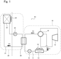
- a refrigeration apparatus R1 shown in FIG 1 is a typical example of a configuration according to Embodiment 1.
- the refrigeration apparatus R1 is configured as an air conditioner.
- the refrigeration apparatus R1 according to Embodiment 1 includes an outdoor-side circuit 10 and an indoor-side circuit 20.
- the outdoor-side circuit 10 includes first piping 11, a compressor 12, a first heat exchanger 13, a first blower 14, an expansion valve 15, a four-way valve 16, a secondary heat exchanger 30, etc.
- the indoor-side circuit 20, as shown by a dashed box in FIG 1 like the outdoor-side circuit 10, includes second piping 21, a pump 22, a second heat exchanger 23, a second blower 24, the secondary heat exchanger 30, etc.
- the secondary heat exchanger 30 is a component shared by both the outdoor-side circuit 10 and the indoor-side circuit 20.
- the compressor 12, the secondary heat exchanger 30, the expansion valve 15, and the first heat exchanger 13 are arranged in this order and serially connected in a loop by the first piping 11 and via the four-way valve 16 to constitute one refrigeration cycle.
- a first working medium containing at least a fluoroolefin circulates in the outdoor-side circuit 10.
- the fluoroolefin contained in the first working medium is, for example, but not limited to, 1,1,2-trifluoroethylene (HFO-1123) in Embodiment 1.
- the first working medium may be a single-component refrigerant consisting only of HFO-1123 or may be a refrigerant mixture containing another refrigerant component in addition to HFO-1123. The details of the first working medium will be described later.
- the compressor 12 compresses the first working medium.
- the first heat exchanger 13 effects heat exchange between the first working medium and outdoor air (outside air).
- the first blower 14 delivers outdoor air toward the first heat exchanger 13.
- the expansion valve 15 is an expansion mechanism that expands the first working medium.
- the discharge outlet and the suction inlet of the compressor 12 are connected to the four-way valve 16.
- the four-way valve 16 switches between different positions to change the flow direction of the first working medium.
- a cooling operation takes place when the four-way valve 16 is in a position to connect the discharge outlet of the compressor 12 to the first heat exchanger 13, while a heating operation takes place when the four-way valve 16 is in a position to connect the discharge outlet of the compressor 12 to the secondary heat exchanger 30.
- the cooling and heating operations will be described later.
- FIG 1 the direction in which the first working medium flows during the cooling operation is shown by a black block arrow F1
- the direction in which the first working medium flows during the heating operation is shown by a white block arrow F2.
- the pump 22, the secondary heat exchanger 30, and the second heat exchanger 23 are arranged in this order and serially connected in a loop by the second piping 21 to constitute one refrigeration cycle.
- the bold dotted line of FIG 1 is a boundary line between the indoor space and the outdoor space.
- the second heat exchanger 23 is located in the indoor space, and the pump 22 and the secondary heat exchanger 30 are located in the outdoor space.
- the pump 22 may be located in the indoor space. All the components of the outdoor-side circuit 10 are located in the outdoor space.
- a second working medium containing no fluoroolefin circulates in the indoor-side circuit 20.
- the second working medium is not limited to a particular composition and may have any composition insofar as the second working medium does not contain any fluoroolefin.
- a known liquid refrigerant or low-pressure refrigerant can be suitably used as the second working medium.
- carbon dioxide (CO 2 ) is used as the second working medium.
- the liquid refrigerant used may be, for example, water, brine composed mainly of water, or an antifreeze fluid. The details of the second working medium will also be described later.
- the pump 22 pumps the second working medium through the second piping 21.
- the second heat exchanger 23 effects heat exchange between the second working medium and indoor air.
- the second blower 24 delivers indoor air toward the second heat exchanger 23.
- the indoor-side circuit 20 does not include any component corresponding to the four-way valve 16 in the outdoor-side circuit 10. Thus, in the indoor-side circuit 20, the second working medium flows and circulates only in one direction. In FIG 1 , the flow direction of the second working medium is shown by a black block arrow F3.
- the secondary heat exchanger 30 is a component shared by both the outdoor-side circuit 10 and the indoor-side circuit 20.
- the secondary heat exchanger 30 effects heat exchange between the first working medium circulating in the outdoor-side circuit 10 and the second working medium circulating in the indoor-side circuit 20. It can therefore be said that the outdoor-side circuit 10 and the indoor-side circuit 20 are thermally connected via the secondary heat exchanger 30.
- the refrigeration apparatus R1 is configured as a dual cycle apparatus including two circuits thermally connected via the secondary heat exchanger 30, and the secondary heat exchanger 30 effects heat exchange between the first and second working media.
- the outdoor-side circuit 10 and the indoor-side circuit 20, which are refrigeration cycles independent of each other, can be controlled together as one refrigeration apparatus R1.
- the compressor 12, the first heat exchanger 13, the first blower 14, the expansion valve 15, the four-way valve 16, the pump 22, the second heat exchanger 23, the second blower 24, and the secondary heat exchanger 30 constituting the refrigeration apparatus R1 are not limited to particular configurations, and any configurations known in the field of refrigeration apparatuses R1 can be suitably employed.
- a known hermetic refrigerant compressor can be used as the compressor 12.
- the hermetic refrigerant compressor may be any kind of compressor such as a reciprocating, rotary, scroll, or screw compressor.
- the electric element of the refrigerant compressor may have the same configuration as any known motor and may be an outer rotor-type motor or an inner rotor-type motor.
- the first heat exchanger 13 is a heat exchanger "located in the outdoor space” and can be regarded as corresponding to a "condenser” of a common refrigeration apparatus.
- the second heat exchanger 23 is a heat exchanger "located in the indoor space” and can be regarded as corresponding to an "evaporator” of a common refrigeration apparatus.
- a heat exchanger known as a condenser can be used as the first heat exchanger 13
- a heat exchanger known as an evaporator can be used as the second heat exchanger 23.
- Examples of such heat exchangers include, but are not limited to, plate heat exchangers, double pipe heat exchangers, and shell-and-tube heat exchangers.
- a known heat exchanger can be suitably used as the secondary heat exchanger 30.
- the secondary heat exchanger 30 effects heat exchange between the first and second working media unlike the first heat exchanger 13 or second heat exchanger 23 which effects heat exchange between a corresponding one of the working media and air (outdoor air or indoor air)
- the type of the heat exchanger used as the secondary heat exchanger 30 can be selected depending on the types of the first and second working media.
- the second working medium may be, for example, a common refrigerant containing a hydrofluorocarbon as a main component, and in this case a plate heat exchanger can be used as the secondary heat exchanger 30.
- a shell-and-tube heat exchanger can be used as the secondary heat exchanger 30.
- a shell-and-tube heat exchanger includes an outer pipe (shell) serving as an enclosure body and a number of inner pipes (tubes) located inside the outer pipe.
- the expansion valve 15 used may be a thermostatic expansion valve, an electronic expansion valve, or any other expansion mechanism.
- the four-way valve 16 the pump 22, the first blower 14, the second blower 24, etc., various known configurations can be suitably employed.
- the following will describe exemplary operations of the refrigeration apparatus R1 described above.
- a cooling operation will be described first.
- the first working medium compressed by the compressor 12 and having a high temperature and a high pressure is delivered to the first heat exchanger 13 via the four-way valve 16 (the direction of the arrow F1).
- the first heat exchanger 13 allows the first working medium to exchange heat with outdoor air (outside air) delivered by the first blower 14 and thus turn into a high-pressure, middle-to-high temperature liquid, which is delivered to the expansion valve 15.
- the first working medium is expanded by the expansion valve 15 and turns into a low-pressure, low-temperature gas-liquid mixture, which is delivered to the secondary heat exchanger 30.
- the secondary heat exchanger 30 effects heat exchange between the first working medium and the second working medium circulating in the indoor-side circuit 20, thus turning the first working medium into a low-pressure, middle-to-low-temperature gas, which is sucked into the suction inlet of the compressor 12 via the four-way valve 16.
- the second working medium is pumped by the pump 22 to the secondary heat exchanger 30 (the direction of the arrow F3).
- the secondary heat exchanger 30 effects heat exchange between the first and second working media; thus, the second working medium is cooled by the first working medium having a low temperature and a low pressure.
- the cooled second working medium is delivered to the second heat exchanger 23 located in the indoor space.
- the second heat exchanger 23 allows the second working medium to exchange heat with indoor air delivered by the second blower 24, and thus the indoor air is cooled by the second working medium and cools the indoor space.
- the first working medium compressed by the compressor 12 and having a high temperature and a high pressure is delivered to the secondary heat exchanger 30 via the four-way valve 16 (the direction of the arrow F2).
- the secondary heat exchanger 30 effects heat exchange between the first working medium and the second working medium circulating in the indoor-side circuit 20, thus turning the first working medium into a high-pressure, middle-to-low-temperature liquid, which is delivered to the expansion valve 15.
- the first working medium is expanded by the expansion valve 15 and turns into a low-temperature, low-pressure gas-liquid mixture, which is delivered to the first heat exchanger 13.
- the first heat exchanger 13 allows the first working medium to exchange heat with outdoor air delivered by the first blower 14 and thus turn into a low-pressure, middle-to-low-temperature gas, which is sucked into the suction inlet of the compressor 12.
- the second working medium is pumped by the pump 22 to the secondary heat exchanger 30.
- the secondary heat exchanger 30 effects heat exchange between the first and second working media; thus, the second working medium is heated by the first working medium having a high temperature and a high pressure.
- the heated second working medium is delivered to the second heat exchanger 23 located in the indoor space.
- the second heat exchanger 23 allows the second working medium to exchange heat with indoor air delivered by the second blower 24, and thus the indoor air is heated by the second working medium and heats the indoor space.
- a fluoroolefin having a low GWP is used in the outdoor-side circuit 10.
- the fluoroolefin is HFO-1123 in Embodiment 1.
- Some of such fluoroolefins have a low GWP, have high cooling ability, and have performance similar to that of R-32 which is currently in widespread use.
- fluoroolefins are likely to undergo disproportionation. The occurrence of disproportionation entails a large amount of heat release, which could induce a chain reaction of disproportionation.
- a refrigerant containing a fluoroolefin is used as the first working medium circulating in the outdoor-side circuit 10
- a refrigerant other than fluoroolefins which can undergo disproportionation is used as the second working medium circulating in the indoor-side circuit 20.
- the secondary heat exchanger 30 which enables heat exchange between the outdoor-side circuit 10 and the indoor-side circuit 20 is located in the outdoor space.
- the first working medium used may be a refrigerant mixture containing propane in addition to a fluoroolefin.
- Propane has physical properties suitable for use as a refrigeration cycle working medium and, when used in combination with a fluoroolefin, exhibits an inhibitory action on disproportionation of the fluoroolefin.
- the first working medium containing a fluoroolefin is a refrigerant mixture further containing propane, satisfactory refrigeration capacity can be achieved along with successful inhibition of disproportionation of the fluoroolefin.
- the first working medium may further contain a disproportionation inhibitor in addition to a fluoroolefin.
- the first working medium may contain a fluoroolefin as a first refrigerant component and propane as a second refrigerant component
- the first working medium may contain a disproportionation inhibitor as a component other than the refrigerant components. In this case, disproportionation of the fluoroolefin can be more successfully inhibited.
- the first working medium contains a fluoroolefin
- propane, a disproportionation inhibitor, or both in the first working medium can effectively reduce or substantially eliminate the possibility that disproportionation occurs in the outdoor-side circuit 10.
- the first working medium may contain an additional refrigerant component other than propane.
- the first working medium used in the outdoor-side circuit 10 contains at least a fluoroolefin (fluoroalkene) as a refrigerant component.
- the fluoroolefin is not limited to a particular type, and examples of the fluoroolefin include: fluoroethylenes such as 1,1,2-trifluoroethylene (HFO-1123), trans-1 ,2-difluoroethylene ( H FO-1132(E)), cis-1,2-difluoroethylene (HFO-1132(Z)), 1,1-difluoroethylene (HFO-1132a), tetrafluoroethylene (FO-1114, TFE), and monofluoroethylene (HFO-1141); and fluoropropenes such as 1,2,3,3,3-pentafluoropropene (HFO-1225ye), 2,3,3,3-tetrafluoropropene (HFO-1234yf), 1,3,3,3-tetrafluoropropene (HFO-1234
- fluoroolefins may be used alone as a refrigerant component, or any suitable combination of two or more of the fluoroolefins may be used as a refrigerant component.
- fluoroolefins the fluoroethylenes are suitable for use as a refrigerant component.
- fluoroethylenes 1,1,2-trifluoroethylene (HFO-1123) is particularly suitable for use.
- the first working medium may further contain a refrigerant component which is a refrigerant other than fluoroolefins.
- a refrigerant is propane. That is, the first working medium used can be a refrigerant mixture of a fluoroolefin and propane.
- the first working medium may further contain an "additional refrigerant component" in addition to the fluoroolefin and propane.
- the additional refrigerant include, but are not limited to, a hydrofluorocarbon (HFC), a saturated hydrocarbon other than propane, and carbon dioxide.
- HFC include: fluoromethanes such as difluoromethane (R-32) and trifluoromethane (R-23); fluoroethanes such as fluoroethane (R-161), 1,1-difluoroethane (R-152a), 1,1,1-trifluoroethane (R-143a), 1,1,2,2-tetrafluoroethane (R-134), 1,1,1,2-tetrafluoroethane (R-134a), pentafluoroethane (R-125), difluoroethane, and trifluoroethane; fluoropropanes such as 1,1,1,3,3-pentafluoropropane (R-245fa), 1,1,1,2,3,3-hexafluoropropane (R-236ea), 1,1,1,3,3,3-hexafluoropropane (R-236fa), and 1,1,1,2,3,3,3-heptafluoropropane (R-161)
- saturated hydrocarbon examples include ethane, n-propane, cyclopropane, n-butane, cyclobutane, isobutane (2-methylpropane), methylcyclopropane, n-pentane, isopentane (2-methylbutane), neopentane (2,2-dimethylpropane), and methylcyclobutane.
- additional refrigerant components may be used alone, or any suitable combination of two or more of the additional refrigerant components may be used as a refrigerant.
- R-32 difluoromethane
- some saturated hydrocarbons can be used as a disproportionation inhibitor.
- a saturated hydrocarbon can be used as both an additional refrigerant component and a disproportionation inhibitor.
- the first working medium contains a fluoroolefin.
- Fluoroolefins are known to undergo disproportionation.
- the first working medium may contain a disproportionation inhibitor that inhibits disproportionation of the fluoroolefin.
- Specific examples of the disproportionation inhibitor include, but are not limited to, saturated hydrocarbons with two to five carbon atoms (other than propane) and haloalkanes with one to four carbon atoms other than haloalkanes all the halogen atoms of which are fluorine.
- a saturated hydrocarbon used as a disproportionation inhibitor will be referred to as a "disproportionation-inhibiting alkane”
- a haloalkane used as a disproportionation inhibitor will be referred to as a “disproportionation-inhibiting haloalkane”.
- the disproportionation-inhibiting alkane used as a disproportionation inhibitor in the present disclosure may be a saturated hydrocarbon (alkane) with two to five carbon atoms, and specific examples of such a saturated hydrocarbon include ethane, cyclopropane, n-butane, cyclobutane, isobutane (2-methylpropane), methylcyclopropane, n-pentane, isopentane (2-methylbutane), neopentane (2,2-dimethylpropane), and methylcyclobutane.
- alkane alkane
- saturated hydrocarbon alkane
- specific examples of such a saturated hydrocarbon include ethane, cyclopropane, n-butane, cyclobutane, isobutane (2-methylpropane), methylcyclopropane, n-pentane, isopentane (2-methylbutane), neopentane (2,2-d
- All of the above-mentioned saturated hydrocarbons are gaseous at normal temperature (n-pentane and methylcyclobutane have the highest boiling point which is about 36°C, and the other hydrocarbons have a boiling point lower than 36°C), and any of the saturated hydrocarbons can be mixed well with the refrigerant component(s) of the first working medium.
- Any saturated hydrocarbon with six or more carbon atoms is not preferred because such a saturated hydrocarbon is liquid at normal temperature and difficult to mix with the refrigerant component(s) of the first working medium.
- Propane which is a saturated hydrocarbon with three carbon atoms, can inhibit disproportionation of fluoroolefins.
- propane is a refrigerant component that can be used in combination with a fluoroolefin in the first working medium; thus, propane is not regarded as a "disproportionation-inhibiting alkane”.
- Cyclopropane which is a cyclic compound and different from linear propane (n-propane) usable as a refrigerant component, can be used as a disproportionation-inhibiting alkane.
- GWP global warming potential
- cyclopentane has a boiling point of 49°C and is liquid at normal temperature; however, cyclopentane may be used as a disproportionation inhibitor in the present disclosure.
- the disproportionation-inhibiting haloalkane used as a disproportionation inhibitor in the present disclosure may be any haloalkane with one to four carbon atoms other than haloalkanes all the halogen atoms of which are fluorine.
- Specific examples of the disproportionation-inhibiting haloalkane include halomethanes (halogenated methanes) which have one carbon atom, haloethanes (halogenated ethanes) which have two carbon atoms, halopropanes (halogenated propanes) which have three carbon atoms, and halobutanes (halogenated butanes) which have four carbon atoms.
- the disproportionation-inhibiting haloalkane used may be one haloalkane selected from halomethanes, haloethanes, halopropanes, and halobutanes, or two or more haloalkanes selected from these disproportionation-inhibiting haloalkanes may be used in any suitable combination.
- two or more haloalkanes selected is intended to mean not only that two or more disproportionation-inhibiting haloalkanes differing in the number of carbon atoms may be selected (for example, a combination of a halomethane and a halomethane) but also that two or more disproportionation-inhibiting haloalkanes having the same number of carbon atoms and having different halogen substituents may be selected (for example, a combination of a first haloethane and a second haloethane different from the first haloethane).
- the halobutane may have a linear structure or may have a branched structure (a structure having the same carbon skeleton as isobutane or 2-methylpropane).
- the disproportionation-inhibiting haloalkane may have a structure represented by the following formula (1).
- X is a halogen atom selected from the group consisting of fluorine (F), chlorine (Cl), bromine (Br), and iodine (I),
- F fluorine
- Cl chlorine
- Br bromine
- I iodine
- p is an integer of 1 or 2
- q is an integer of 0 or more
- r is an integer of 1 or more
- the sum of q and r is 2p + 2
- the halogen atoms X are the same or different when r is 2 or more.
- Any haloalkane which is represented by the formula (1) but which contains only F as the halogen atom(s) X is excluded from candidates for the disproportionation-inhibiting haloalkane. This is because any disproportionation-inhibiting haloalkane which contains only F as the halogen atom(s) X is a compound usable as an additional refrigerant component and substantially fails to function as a disproportionation inhibitor.
- the halogen atom X may be at least one of F, Cl, Br, and I as stated above and is preferably at least I.
- the halogen atoms X preferably include at least F and I.
- some disproportionation-inhibiting haloalkanes represented by the formula (1) are compounds having a relatively high ozone depletion potential (ODP) and/or a relatively high global warming potential (GWP).
- a disproportionation-inhibiting haloalkane added as the disproportionation inhibitor to the first working medium can effectively inhibit disproportionation of the fluoroolefin or retard rapid progress of disproportionation of the fluoroolefin even when the amount of the added disproportionation-inhibiting haloalkane is relatively small.
- a disproportionation-inhibiting haloalkane is used in combination with another disproportionation inhibitor such as a disproportionation-inhibiting alkane, the total amount of the disproportionation inhibitors added to the first working medium is sufficiently small relative to the total amount of the first working medium.
- the use of a disproportionation-inhibiting haloalkane does not cause any significant impact on the environment even when the disproportionation-inhibiting haloalkane has a relatively high ODP or GWP.
- disproportionation-inhibiting haloalkanes represented by the formula (1) include, but are not limited to: halomethanes such as (mono)iodomethane (CH 3 I), diiodomethane (CH 2 I 2 ), dibromomethane (CH 2 Br 2 ), bromomethane (CH 3 Br), dichloromethane (CH 2 Cl 2 ), chloroiodomethane (CH 2 ClI), dibromochloromethane (CHBr 2 Cl), tetraiodomethane (CI 4 ), carbon tetrabromide (CBr 4 ), bromotrichloromethane (CBrCl 3 ), dibromodichloromethane (CBr 2 Cl 2 ), tribromofluoromethane (CBr 3 F), fluorodiiodomethane (CHFI 2 ), difluorodiiodomethane (CF 2 I 2 ), dibromodifluoromethane (CHFI
- disproportionation-inhibiting haloalkanes may be used alone, or two or more thereof may be used in any suitable combination.
- disproportionation-inhibiting haloalkanes at least one selected from the group consisting of diiodomethane (CH 2 I 2 ), difluorodiiodomethane (CF 2 I 2 ), trifluoroiodomethane (CF 3 I), difluoroiodomethane (CHF 2 I), 1-bromo-2-iodo-tetrafluoroethane (CF 2 BrCF 2 1), and 1,1,1-trifluoro-2-iodoethane (CF 3 CH 2 I) is particularly preferred in terms of factors such as availability, ODP value, and handleability.
- the first working medium is a refrigerant containing at least a fluoroolefin (fluoroalkene) and may contain propane (R-290) or an additional refrigerant component as necessary.
- the first working medium may contain a disproportionation inhibitor as necessary.
- the amounts (contents) of the fluoroolefin and the propane are not limited to particular values, and the amount (content) of the disproportionation inhibitor is not limited to a particular value either.
- the amount of the fluoroolefin is 50% by mass or more and may be 60% by mass or more, 70% by mass or more, or 80% by mass or more based on 100% by mass of the total amount of the first working medium.
- the first working medium is a refrigerant mixture containing propane
- the amount of the propane is less than 50% by mass and may be 40% by mass or less, 30% by mass or less, or 20% by mass or less based on 100% by mass of the total amount of the refrigerant mixture.
- 1,1,2-trifluoroethylene (HFO-1123) is suitable for use as the fluoroolefin, although the fluoroolefin is not limited to 1,1,2-trifluoroethylene (HFO-1123) or any other particular fluoroolefin.
- the second working medium used in the refrigeration apparatus R1 according to the present disclosure contains no fluoroolefin (fluoroalkene) as a refrigerant component, unlike the first working medium.
- the second working medium need not be a fluorocarbon-based refrigerant like the first working medium and may be, for example, a liquid refrigerant or a natural refrigerant other than fluorocarbon-based refrigerants.
- a gaseous refrigerant such as a fluorocarbon-based refrigerant
- a low-pressure refrigerant which is not subject to High Pressure Gas Safety Act in Japan can be suitably used as the gaseous refrigerant.
- the second working medium is a fluorocarbon-based refrigerant
- a refrigerant having the same composition as the above-described first working medium except for containing no fluoroolefin can be suitably used as the fluorocarbon-based refrigerant.
- the second working medium is a natural refrigerant, for example, ammonia, carbon dioxide (CO 2 gas), a hydrocarbon, or nitrogen can be suitably used as the natural refrigerant.
- the hydrocarbon include propane and other saturated hydrocarbons as mentioned above.
- the second working medium is a liquid refrigerant such as brine
- the liquid refrigerant include: a lower alcohol such as methanol or ethanol; an aqueous antifreeze fluid containing such a lower alcohol; a lower glycol such as ethylene glycol or propylene glycol; an aqueous antifreeze fluid containing such a lower glycol; and an aqueous solution of an inorganic salt such as an aqueous calcium chloride solution.
- the first working medium is a fluorocarbon-based gaseous refrigerant containing a fluoroolefin
- the second working medium is a liquid refrigerant or a low-pressure refrigerant which is not subject to High Pressure Gas Safety Act in Japan.
- the first and second working media may contain additives or other components known in the field of refrigeration apparatuses or refrigeration cycles.
- the first working medium to be compressed by the compressor 12 may contain, as its component, a refrigerating machine oil held in the compressor 12.
- a refrigeration apparatus R2 shown in FIG 2 is a typical example of a configuration according to Embodiment 2. As shown in FIG 2 and similarly to the refrigeration apparatus R2 according to Embodiment 1 described above, the refrigeration apparatus R2 according to Embodiment 2 includes the outdoor-side circuit 10 and the indoor-side circuit 20, which are thermally connected by the secondary heat exchanger 30.
- the refrigeration apparatus R2 according to Embodiment 2 has a basic configuration identical to that of the refrigeration apparatus R1 according to Embodiment 1 described above.
- the first working medium circulating in the outdoor-side circuit 10 and the second working medium circulating in the indoor-side circuit 20 are also as described above for Embodiment 1.
- those features of the refrigeration apparatus R2 according to Embodiment 2 which are common to the refrigeration apparatus R1 according to Embodiment 1 will not be described in detail below.
- the refrigeration apparatus R2 according to Embodiment 2 differs from the refrigeration apparatus R1 according to Embodiment 1 in that, as shown in FIG 2 , the outdoor-side circuit 10 further includes bypass piping 17 connected to the first piping 11 in parallel to the secondary heat exchanger 30 and including a shut-off valve 31.
- the indoor-side circuit 20 differs from that of Embodiment 1 in that the indoor-side circuit 20 includes a gas-liquid separator 25 located downstream of the secondary heat exchanger 30 in the flow direction of the second working medium (the direction of the arrow F3), connected to the second piping, and including a safety valve 26.
- the outdoor-side circuit 10 and the indoor-side circuit 20 differ from those of Embodiment 1 in that the outdoor-side and indoor-side circuits 10 and 20 include shut-off valves 32 to 35 located upstream or downstream of the secondary heat exchanger 30 in the flow direction of the first or second working medium. As shown in FIG 2 , both the bypass piping 17 and the gas-liquid separator 25 are located in the outdoor space.
- the bypass piping 17 of the outdoor-side circuit 10 is located between the four-way valve 16 and the expansion valve 15 and connected to the first piping 11 in parallel to the secondary heat exchanger 30.
- the bypass piping 17 is connected to the first piping 11 in parallel to the secondary heat exchanger 30.
- the bypass piping 17 is provided with the bypass piping shut-off valve 31.
- the first piping 11 is provided with the outdoor-side flow shut-off valves 32 and 33, between which the secondary heat exchanger 30 is located.
- the compressor 12 is connected to the first piping 11 via the four-way valve 16, and the four-way valve 16 switches between different positions to change the flow direction of the first working medium.
- the first working medium compressed by the compressor 12 is delivered to the first heat exchanger 13 through the four-way valve 16 (the direction of the arrow F1).
- the first working medium flows into the secondary heat exchanger 30 through the first heat exchanger 13 and the expansion valve 15.
- the first working medium compressed by the compressor 12 is delivered to the secondary heat exchanger 30 through the four-way valve 16 (the direction of the arrow F2).
- the outdoor-side flow shut-off valve 32 serves as a shut-off valve that blocks inflow into the secondary heat exchanger 30, while the outdoor-side flow shut-off valve 33 serves as a shut-off valve that blocks outflow from the secondary heat exchanger 30.
- the outdoor-side flow shut-off valve 33 serves as a shut-off valve that blocks inflow into the secondary heat exchanger 30, while the outdoor-side flow shut-off valve 32 serves as a shut-off valve that blocks outflow from the secondary heat exchanger 30.
- the outdoor-side flow shut-off valves 32 and 33 are regarded as valves that block inflow of the first working medium into the secondary heat exchanger 30 and outflow of the first working medium from the secondary heat exchanger 30, and neither of the outdoor-side flow shut-off valves 32 and 33 is uniquely defined as a valve that blocks only inflow or outflow of the first working medium.
- the bypass piping shut-off valve 31 is normally closed, and the outdoor-side flow shut-off valves 32 and 33 are normally open. Thus, when the outdoor-side circuit 10 is in a normal operation, the first working medium flows through the secondary heat exchanger 30. Once the bypass piping shut-off valve 31 is opened and the outdoor-side flow shut-off valves 32 and 33 are closed, the first working medium flows between the four-way valve 16 and the expansion valve 15 without passing through the secondary heat exchanger 30 (while bypassing the secondary heat exchanger 30).
- the outdoor-side circuit 10 is provided with the bypass piping 17 for bypassing the secondary heat exchanger 30 and the bypass piping 17 includes the bypass piping shut-off valve 31, it becomes possible to choose whether to allow the first working medium containing a fluoroolefin to flow through the secondary heat exchanger 30 or allow the first working medium to bypass the secondary heat exchanger 30 while circulating in the outdoor-side circuit 10.
- the impact of the disproportionation on the secondary heat exchanger 30 can be further reduced, and the impact of the disproportionation on the indoor equipment can be more effectively avoided.
- the presence of the outdoor-side flow shut-off valves 32 and 33, which block inflow of the first working medium into the secondary heat exchanger 30 and outflow of the first working medium from the secondary heat exchanger 30, makes it possible to stop the first working medium from flowing through the secondary heat exchanger 30 in the event that disproportionation of the fluoroolefin occurs in the outdoor-side circuit 10.
- the possibility of disproportionation having an impact on the secondary heat exchanger 30, and the possibility of disproportionation having an impact on the indoor-side circuit 20 through the secondary heat exchanger 30, can be more effectively reduced.
- the opening and closing of the bypass piping shut-off valve 31 may be in conjunction with or independent of the opening and closing of the outdoor-side flow shut-off valves 32 and 33.
- the outdoor-side flow shut-off valves 32 and 33 may be closed in conjunction with the opening of the bypass piping shut-off valve 31.
- the shut-off valves 31 to 33 need not be operated in conjunction with one another. In this case, the outdoor-side flow shut-off valves 32 and 33 may be operated in conjunction with each other.
- the shut-off valves 31 to 33 need not be operated in conjunction with one another, and it suffices to close the outdoor-side flow shut-off valves 32 and 33.
- the outdoor-side flow shut-off valves 32 and 33 need not be operated in conjunction with each other.
- the second piping 21 is provided with an indoor-side inflow shut-off valve 34 located to block inflow of the second working medium into the secondary heat exchanger 30 (located upstream of the secondary heat exchanger 30 in the flow direction of the second working medium).
- the indoor-side inflow shut-off valve 34 is normally open, and the closing of the indoor-side inflow shut-off valve 34 takes place in conjunction with the operation of the pump 22. Specifically, the pump 22 is stopped when the indoor-side inflow shut-off valve 34 is closed to block inflow of the second working medium into the secondary heat exchanger 30.
- the second piping 21 is further provided with an indoor-side outflow shut-off valve 35 located to block outflow of the second working medium from the gas-liquid separator 25 (located downstream of the gas-liquid separator 25 in the flow direction of the second working medium).
- the indoor-side outflow shut-off valve 35 is also normally open.
- the inclusion of the gas-liquid separator 25 in the indoor-side circuit 20 is advantageous because, in case that the first working medium enters the indoor-side circuit 20 within the secondary heat exchanger 30, the first working medium mixed into the second working medium can be separated by the gas-liquid separator 25.
- the gas-liquid separator 25 since the gas-liquid separator 25 is located in the outdoor space, the first working medium entering the indoor-side circuit 20 can be discharged to the outdoor space at a given pressure through the safety valve 26.
- the presence of the indoor-side outflow shut-off valve 35 located to block outflow of the second working medium from the gas-liquid separator 25 offers, for example, the following advantage: in case that the first working medium enters the indoor-side circuit 20 within the secondary heat exchanger 30 and reaches the gas-liquid separator 25, the indoor-side outflow shut-off valve 35 can be closed to avoid the possibility that the first working medium flows into a region downstream of the gas-liquid separator 25 in the indoor-side circuit 20.
- the possibility of the impact affecting the indoor equipment can be more effectively avoided.
- the presence of the indoor-side inflow shut-off valve 34 located to block inflow of the second working medium into the secondary heat exchanger 30 offers the following advantage: in case that disproportionation of the fluoroolefin occurs in the outdoor-side circuit 10, the indoor-side inflow shut-off valve 34 can be closed in the indoor-side circuit 20 to stop inflow of the second working medium into the secondary heat exchanger 30 and, as stated above, the pump 22 is stopped in conjunction with the closing of the indoor-side inflow shut-off valve 34.
- the possibility of the disproportionation having an impact on the secondary heat exchanger 30 can be further reduced, and the possibility of the impact affecting the indoor equipment can be more effectively avoided.
- shut-off valves 31 to 35 are not limited to particular configurations, and any control valves known in the field of refrigeration apparatuses can be suitably used. Typically, gate valves or ball valves, which have high on-off performance in terms of permitting and blocking passage of fluids such as refrigerants, can be suitably used. If necessary, any other known control valves may be used.
- the gas-liquid separator 25 is not limited to a particular configuration, and any known configuration can be suitably employed.
- surface tension-type or centrifugal-type gas-liquid separators are generally known in the field of refrigerants, and any of these types of gas-liquid separators can be used as the gas-liquid separator 25.
- an oil separator-type gas-liquid separator or a gas-liquid separator including a tank (these types will be collectively referred to as "oil separator type" for convenience of explanation) is typically used as the gas-liquid separator 25.
- the gas-liquid separator 25 of the oil separator type includes: a tank having an internal space with a given volume; gas piping and inlet piping connected to an upper portion of the tank; and outlet piping connected to a lower portion of the tank.
- the liquid/gas refrigerant mixture flows into the tank through the inlet piping connected to the upper portion of the tank and is retained in the tank for some time, during which the mixture becomes separated into the liquid refrigerant and the gaseous refrigerant.
- the liquid refrigerant flows out of the tank through the outlet piping connected to the lower portion of the tank, while the gaseous refrigerant flows out of the tank through the gas piping connected to the upper portion of the tank.
- the mixture can be retained in the tank for some time to separate the mixture into the second working medium which is a liquid refrigerant and the first working medium which is a gaseous refrigerant.
- the mixture of the gaseous refrigerants may be expanded by an expansion valve to make one of the gaseous refrigerants easier to evaporate, and the expanded mixture may be retained in the tank at a controlled internal pressure for some time to separate the mixture into a liquid refrigerant and a gaseous refrigerant.
- the separator may, for example, include liquid piping in addition to the outlet piping. The liquid piping is connected to an expansion valve, and the liquid refrigerant can be expanded by the expansion valve and turned into a gaseous refrigerant to be returned to the second piping 21.
- the refrigeration apparatus R2 may include the bypass piping 17 and the shut-off valves 31 to 33 and be devoid of the gas-liquid separator 25 and the shut-off valves 34 and 35.
- the refrigeration apparatus R2 may include the gas-liquid separator 25 and the shut-off valves 34 and 35 and be devoid of the bypass piping 17 and the shut-off valves 31 to 33.
- the refrigeration apparatus R2 according to Embodiment 2 may be devoid of one or more of the shut-off valves 31 to 35.
- the indoor-side circuit 20 may include only the indoor-side inflow shut-off valve 34 and be devoid of the indoor-side outflow shut-off valve 35.
- the indoor-side circuit 20 may include only the indoor-side outflow shut-off valve 35 and be devoid of the indoor-side inflow shut-off valve 34.
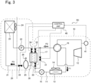
- a refrigeration apparatus R3 shown in FIG 3 is a typical example of a configuration according to Embodiment 3. As shown in FIG 3 and similarly to the refrigeration apparatuses R1 and R2 according to Embodiments 1 and 2 described above, the refrigeration apparatus R3 according to Embodiment 3 includes the outdoor-side circuit 10 and the indoor-side circuit 20, which are thermally connected by the secondary heat exchanger 30.
- the refrigeration apparatus R3 according to Embodiment 3 differs from the refrigeration apparatus R1 or R2 according to Embodiment 1 or 2 in that, as shown in FIG 3 , the refrigeration apparatus R3 includes a temperature sensor 41 (first working medium temperature detector) that measures (detects) the temperature of the first working medium flowing in the first piping. As shown in FIG 3 , the temperature of the flowing first working medium as measured by the temperature sensor 41 is used in control performed by a control unit 40.
- a temperature sensor 41 first working medium temperature detector
- the control unit 40 performs control also in the refrigeration apparatus R1 or R2 according to Embodiment 1 or 2 described above.
- Embodiment 3 control that the control unit 40 performs using a detection result obtained by the temperature sensor 41 will be described.
- FIG 3 shows the control unit 40 and schematically depicts a control signal by a dotted arrow.
- the control unit 40 controls the operation of the refrigeration apparatus R3 (the operation of the refrigeration apparatus R1 or R2 according to Embodiment 1 or 2 described above is also controlled by the control unit 40).
- the control unit 40 controls the compressor 12, the four-way valve 16, the pump 22, the first blower 14, the second blower 24 etc., although control signals related to these devices are omitted in FIG 3 .
- the control unit 40 upon determining that the temperature of the first working medium as measured (detected) by the temperature sensor 41 has reached a predetermined temperature, the control unit 40 performs control to open the bypass piping shut-off valve 31 of the bypass piping 17.
- control unit 40 continually monitors the temperature of the first working medium containing a fluoroolefin by means of the temperature sensor 41 and, upon determining that the temperature has reached the predetermined temperature, opens the bypass piping shut-off valve 31 to allow the first working medium to flow into the bypass piping 17.
- disproportionation of the fluoroolefin is believed to be induced, for example, by high pressure or generated heat, and the occurrence of disproportionation entails a large amount of heat release.
- the temperature of the first working medium can be used as a direct indicator for determining the occurrence or risk of disproportionation.
- the bypass piping shut-off valve 31 can be controlled to allow the first working medium to bypass the secondary heat exchanger 30 and flow through the bypass piping 17.
- the possibility of disproportionation having an impact on the secondary heat exchanger 30 can be further reduced, and the possibility of the impact affecting the indoor equipment can be more effectively avoided.
- the outdoor-side flow shut-off valves 32 and 33 may also be controlled and opened in conjunction with the closing of the bypass piping shut-off valve 31.
- the control unit 40 upon determining, based on a measurement result obtained by the temperature sensor 41, that the temperature of the first working medium has reached the predetermined temperature, the control unit 40 performs control to close the outdoor-side flow shut-off valves 32 and 33 and stop the operation of the outdoor-side circuit 10.
- the possibility of disproportionation having an impact on the secondary heat exchanger 30 can be further reduced, and a chain reaction of disproportionation can be inhibited in the outdoor-side circuit 10.
- the outdoor-side circuit 10 need not necessarily include the bypass piping 17.
- the control unit 40 may further perform control to close the indoor-side inflow shut-off valve 34 of the indoor-side circuit 20 or stop the operation of the indoor-side circuit 20 in conjunction with performing control to open the bypass piping shut-off valve 31 or performing control to close the outdoor-side flow shut-off valves 32 and 33 and stop the operation of the outdoor-side circuit 10. In this case, the possibility of disproportionation having an impact on the indoor-side circuit 20 can be further reduced.
- Embodiment 3 when closing the outdoor-side flow shut-off valves 32 and 33 to block inflow of the first working medium into the secondary heat exchanger 30, the control unit 40 need not perform control to stop the operation of the outdoor-side circuit 10 or the indoor-side circuit 20.
- control unit 40 may further perform control to open the bypass piping shut-off valve 31.
- This also makes it possible to prevent the first working medium from flowing through the secondary heat exchanger 30.
- the control unit 40 may let the outdoor-side circuit 10 continue to operate by allowing the first working medium to flow through the bypass piping 17 and, once the measurement result obtained by the temperature sensor 41 falls below the predetermined temperature, may perform control to open the outdoor-side flow shut-off valves 32 and 33.
- the control unit 40 may let the indoor-side circuit 20 continue to operate.
- the indoor-side inflow shut-off valve 34 may be left open while the indoor-side outflow shut-off valve 35 is closed, so that the first working medium (or any other substance such as a reaction product of disproportionation) mixed in the second working medium may be removed by the gas-liquid separator 25.
- the temperature sensor 41 is not limited to a particular configuration, and any temperature detector known in the field of refrigeration apparatuses can be used. Typical examples of the temperature sensor 41 include, but are not limited to, a resistance temperature detector, a thermocouple temperature sensor, and a thermistor.
- the temperature sensor 41 is not limited to a particular location on the first piping 11 and may be at any location where the temperature sensor 41 can reliably measure the temperature of the first working medium. Typically, the temperature sensor 41 may be at a location where the temperature sensor 41 can measure the temperature of the first working medium discharged from the compressor 12 (location in a pipe connected to the discharge outlet of the compressor 12).
- the control unit 40 is not limited to a particular configuration, and any commonly known configuration can be suitably employed.
- the control unit 40 is configured as hardware including various processors and integrated circuits (ICs) such as ASIC (Application Specific Integrated Circuit), FPGA (Field Programmable Gate Array), and CPLD (Complex Programmable Logic Device).
- ICs integrated circuits
- This sort of hardware can be considered circuitry including active elements (such as transistors) and passive elements (such as capacitors and resistors).
- the integrated circuits may include a storage device, or the hardware may include a storage device such as a volatile memory (RAM) or a non-volatile memory (ROM) independent of the integrated circuits.
- the storage device stores software including control programs for performing the control procedures described above and data necessary for executing the control programs.
- the control unit 40 is configured as a combination of hardware and software, and the software may be any software that can constitute the control unit 40 together with the hardware.
- a refrigeration apparatus including: a first heat exchanger; a second heat exchanger; a compressor; and an expansion mechanism, wherein the first heat exchanger, the compressor, and the expansion mechanism are located in an outdoor space and connected to first piping that allows a first working medium to circulate through the first heat exchanger, the compressor, and the expansion mechanism, the first heat exchanger, the compressor, the expansion mechanism, and the first piping constituting an outdoor-side circuit, the second heat exchanger is located in an indoor space and connected to second piping that allows a second working medium to circulate through the second heat exchanger, the second heat exchanger and the second piping constituting an indoor-side circuit, the refrigeration apparatus further includes a secondary heat exchanger located between the first piping and the second piping to effect heat exchange between the first working medium and the second working medium, the secondary heat exchanger is located in the outdoor space, the first working medium contains at least a fluoroolefin, and the second working medium contains no fluoroolefin.
- the refrigeration apparatus according to technology 1 or 2, wherein the indoor-side circuit includes a pump that pumps the second working medium to the second heat exchanger, and an indoor-side inflow shut-off valve that blocks inflow of the second working medium into the secondary heat exchanger, and the pump is stopped in case that the indoor-side inflow shut-off valve blocks the inflow of the second working medium.
- the indoor-side circuit includes a pump that pumps the second working medium to the second heat exchanger, and an indoor-side inflow shut-off valve that blocks inflow of the second working medium into the secondary heat exchanger, and the pump is stopped in case that the indoor-side inflow shut-off valve blocks the inflow of the second working medium.
- the refrigeration apparatus according to any one of technologies 1 to 3, wherein the indoor-side circuit further includes a gas-liquid separator connected to the second piping and located in the outdoor space, and the gas-liquid separator includes a safety valve that discharges a gas at a predetermined pressure.
- the refrigeration apparatus according to any one of technologies 2 to 5, further including: a controller; and a first working medium temperature detector that measures a temperature of the first working medium flowing in the first piping, wherein the controller opens the shut-off valve of the bypass piping in case that the temperature measured by the first working medium temperature detector has reached a predetermined temperature.
- the refrigeration apparatus according to any one of technologies 2 to 5, further including: a controller; and a first working medium temperature detector that measures a temperature of the first working medium flowing in the first piping, wherein the outdoor-side circuit further includes an outdoor-side flow shut-off valve that blocks inflow of the first working medium into the secondary heat exchanger and outflow of the first working medium from the secondary heat exchanger, and the controller closes the outdoor-side flow shut-off valve and stops operation of the outdoor-side circuit in case that the temperature measured by the first working medium temperature detector has reached a predetermined temperature.
- the present invention can be applied widely and suitably in the field of refrigeration apparatuses, in particular in the field of refrigeration apparatuses using a fluoroolefin-containing working medium in a refrigeration cycle including a compressor.
Landscapes
- Engineering & Computer Science (AREA)
- Physics & Mathematics (AREA)
- Mechanical Engineering (AREA)
- Thermal Sciences (AREA)
- General Engineering & Computer Science (AREA)
- Other Air-Conditioning Systems (AREA)
Applications Claiming Priority (2)
| Application Number | Priority Date | Filing Date | Title |
|---|---|---|---|
| JP2022101354 | 2022-06-23 | ||
| PCT/JP2023/022264 WO2023248923A1 (ja) | 2022-06-23 | 2023-06-15 | 冷凍装置 |
Publications (2)
| Publication Number | Publication Date |
|---|---|
| EP4545875A1 true EP4545875A1 (de) | 2025-04-30 |
| EP4545875A4 EP4545875A4 (de) | 2025-09-24 |
Family
ID=89379883
Family Applications (1)
| Application Number | Title | Priority Date | Filing Date |
|---|---|---|---|
| EP23827109.2A Pending EP4545875A4 (de) | 2022-06-23 | 2023-06-15 | Gefriergerät |
Country Status (5)
| Country | Link |
|---|---|
| US (1) | US20250377139A1 (de) |
| EP (1) | EP4545875A4 (de) |
| JP (1) | JPWO2023248923A1 (de) |
| CN (1) | CN119365736A (de) |
| WO (1) | WO2023248923A1 (de) |
Family Cites Families (16)
| Publication number | Priority date | Publication date | Assignee | Title |
|---|---|---|---|---|
| JP3518475B2 (ja) * | 2000-03-24 | 2004-04-12 | ダイキン工業株式会社 | ヒートポンプ式給湯装置 |
| US7028494B2 (en) * | 2003-08-22 | 2006-04-18 | Carrier Corporation | Defrosting methodology for heat pump water heating system |
| JP5113447B2 (ja) * | 2007-08-09 | 2013-01-09 | 東芝キヤリア株式会社 | ヒートポンプ給湯装置の制御方法 |
| JP6264688B2 (ja) | 2014-02-10 | 2018-01-24 | パナソニックIpマネジメント株式会社 | 冷凍装置 |
| EP3118542B1 (de) * | 2014-03-14 | 2021-05-19 | Mitsubishi Electric Corporation | Kühlkreisvorrichtung |
| JP6223545B2 (ja) * | 2014-03-17 | 2017-11-01 | 三菱電機株式会社 | 冷凍装置 |
| WO2015140873A1 (ja) * | 2014-03-17 | 2015-09-24 | 三菱電機株式会社 | 冷凍装置、及び、冷凍装置の制御方法 |
| JP6497582B2 (ja) | 2015-03-13 | 2019-04-10 | パナソニックIpマネジメント株式会社 | 冷凍機ユニット |
| JP6555584B2 (ja) | 2015-09-11 | 2019-08-07 | パナソニックIpマネジメント株式会社 | 冷凍装置 |
| JPWO2017145826A1 (ja) * | 2016-02-24 | 2018-12-13 | Agc株式会社 | 冷凍サイクル装置 |
| JP6380500B2 (ja) * | 2016-10-17 | 2018-08-29 | ダイキン工業株式会社 | 冷凍装置 |
| WO2018154628A1 (ja) * | 2017-02-21 | 2018-08-30 | 三菱電機株式会社 | 空気調和装置 |
| GB2578036B (en) * | 2017-07-27 | 2021-05-19 | Mitsubishi Electric Corp | Air-conditioning system and method of sealing heat medium |
| JP7149494B2 (ja) * | 2018-03-19 | 2022-10-07 | パナソニックIpマネジメント株式会社 | 冷凍サイクル装置 |
| WO2021140589A1 (ja) * | 2020-01-08 | 2021-07-15 | 三菱電機株式会社 | 空気調和装置 |
| JP7494504B2 (ja) * | 2020-03-17 | 2024-06-04 | 三菱電機株式会社 | ヒートポンプ装置 |
-
2023
- 2023-06-15 CN CN202380047346.4A patent/CN119365736A/zh active Pending
- 2023-06-15 JP JP2024528947A patent/JPWO2023248923A1/ja active Pending
- 2023-06-15 EP EP23827109.2A patent/EP4545875A4/de active Pending
- 2023-06-15 US US18/877,011 patent/US20250377139A1/en active Pending
- 2023-06-15 WO PCT/JP2023/022264 patent/WO2023248923A1/ja not_active Ceased
Also Published As
| Publication number | Publication date |
|---|---|
| US20250377139A1 (en) | 2025-12-11 |
| WO2023248923A1 (ja) | 2023-12-28 |
| JPWO2023248923A1 (de) | 2023-12-28 |
| CN119365736A (zh) | 2025-01-24 |
| EP4545875A4 (de) | 2025-09-24 |
Similar Documents
| Publication | Publication Date | Title |
|---|---|---|
| RU2544662C2 (ru) | Трехкомпонентные композиции для высокомощного охлаждения | |
| US10035938B2 (en) | Heat transfer fluid replacing R-134a | |
| JP6884572B2 (ja) | 冷凍サイクル用作動媒体および冷凍サイクルシステム | |
| JP6895622B2 (ja) | 冷凍サイクル用作動媒体および冷凍サイクルシステム | |
| JP6899529B2 (ja) | 冷凍サイクル用作動媒体および冷凍サイクルシステム | |
| JP7060017B2 (ja) | 熱サイクル用作動媒体、熱サイクルシステム用組成物および熱サイクルシステム | |
| BR112016016341B1 (pt) | Fluido de operação para ciclo térmico, composição para sistema de ciclo térmico e sistema de ciclo térmico | |
| US20130255284A1 (en) | Refrigerants containing (e)-1,1,1,4,4,4-hexafluorobut-2-ene | |
| CN105452417A (zh) | 热循环用工作介质、热循环系统用组合物以及热循环系统 | |
| US11149177B2 (en) | Working fluid for heat cycle | |
| CN115397943A (zh) | 冷冻循环用工作介质和冷冻循环系统 | |
| JP2024534966A (ja) | テトラフルオロプロペン、テトラフルオロエタン及びペンタフルオロプロペンを含有する組成物、並びにその使用 | |
| EP4545875A1 (de) | Gefriergerät | |
| JP7320785B2 (ja) | 冷凍サイクル用作動媒体および冷凍サイクルシステム | |
| WO2018180349A1 (ja) | 冷媒循環装置および冷媒循環方法 | |
| EP4567347A1 (de) | Gefriergerät | |
| US12410353B2 (en) | Mixed refrigerant composition and heat pump including the same | |
| US20250289987A1 (en) | Air conditioner | |
| EP4567086A1 (de) | Kältekreislaufarbeitsmedium und kältekreislaufsystem | |
| US20250059421A1 (en) | Mixed refrigerant composition and heat pump including the same | |
| WO2025004880A1 (ja) | 冷凍サイクル用作動媒体および冷凍サイクルシステム | |
| JP2025007047A (ja) | 冷凍サイクル用作動媒体および冷凍サイクルシステム | |
| WO2025004888A1 (ja) | 冷凍サイクル用作動媒体および冷凍サイクルシステム | |
| KR20250010661A (ko) | 프로필렌 및 플루오로카본을 함유하는 냉매 조성물 및 이의 용도 | |
| JP2025059402A (ja) | 冷凍サイクル装置 |
Legal Events
| Date | Code | Title | Description |
|---|---|---|---|
| STAA | Information on the status of an ep patent application or granted ep patent |
Free format text: STATUS: THE INTERNATIONAL PUBLICATION HAS BEEN MADE |
|
| PUAI | Public reference made under article 153(3) epc to a published international application that has entered the european phase |
Free format text: ORIGINAL CODE: 0009012 |
|
| STAA | Information on the status of an ep patent application or granted ep patent |
Free format text: STATUS: REQUEST FOR EXAMINATION WAS MADE |
|
| 17P | Request for examination filed |
Effective date: 20250123 |
|
| AK | Designated contracting states |
Kind code of ref document: A1 Designated state(s): AL AT BE BG CH CY CZ DE DK EE ES FI FR GB GR HR HU IE IS IT LI LT LU LV MC ME MK MT NL NO PL PT RO RS SE SI SK SM TR |
|
| A4 | Supplementary search report drawn up and despatched |
Effective date: 20250826 |
|
| RIC1 | Information provided on ipc code assigned before grant |
Ipc: F25B 1/00 20060101AFI20250820BHEP Ipc: F25B 7/00 20060101ALI20250820BHEP |
|
| DAV | Request for validation of the european patent (deleted) | ||
| DAX | Request for extension of the european patent (deleted) |