EP4567347A1 - Gefriergerät - Google Patents
Gefriergerät Download PDFInfo
- Publication number
- EP4567347A1 EP4567347A1 EP23850037.5A EP23850037A EP4567347A1 EP 4567347 A1 EP4567347 A1 EP 4567347A1 EP 23850037 A EP23850037 A EP 23850037A EP 4567347 A1 EP4567347 A1 EP 4567347A1
- Authority
- EP
- European Patent Office
- Prior art keywords
- refrigerant
- working medium
- heat exchanger
- piping
- refrigeration cycle
- Prior art date
- Legal status (The legal status is an assumption and is not a legal conclusion. Google has not performed a legal analysis and makes no representation as to the accuracy of the status listed.)
- Pending
Links
Images

Classifications
-
- F—MECHANICAL ENGINEERING; LIGHTING; HEATING; WEAPONS; BLASTING
- F25—REFRIGERATION OR COOLING; COMBINED HEATING AND REFRIGERATION SYSTEMS; HEAT PUMP SYSTEMS; MANUFACTURE OR STORAGE OF ICE; LIQUEFACTION SOLIDIFICATION OF GASES
- F25B—REFRIGERATION MACHINES, PLANTS OR SYSTEMS; COMBINED HEATING AND REFRIGERATION SYSTEMS; HEAT PUMP SYSTEMS
- F25B41/00—Fluid-circulation arrangements
- F25B41/40—Fluid line arrangements
-
- F—MECHANICAL ENGINEERING; LIGHTING; HEATING; WEAPONS; BLASTING
- F25—REFRIGERATION OR COOLING; COMBINED HEATING AND REFRIGERATION SYSTEMS; HEAT PUMP SYSTEMS; MANUFACTURE OR STORAGE OF ICE; LIQUEFACTION SOLIDIFICATION OF GASES
- F25B—REFRIGERATION MACHINES, PLANTS OR SYSTEMS; COMBINED HEATING AND REFRIGERATION SYSTEMS; HEAT PUMP SYSTEMS
- F25B13/00—Compression machines, plants or systems, with reversible cycle
-
- C—CHEMISTRY; METALLURGY
- C09—DYES; PAINTS; POLISHES; NATURAL RESINS; ADHESIVES; COMPOSITIONS NOT OTHERWISE PROVIDED FOR; APPLICATIONS OF MATERIALS NOT OTHERWISE PROVIDED FOR
- C09K—MATERIALS FOR MISCELLANEOUS APPLICATIONS, NOT PROVIDED FOR ELSEWHERE
- C09K5/00—Heat-transfer, heat-exchange or heat-storage materials, e.g. refrigerants; Materials for the production of heat or cold by chemical reactions other than by combustion
- C09K5/02—Materials undergoing a change of physical state when used
- C09K5/04—Materials undergoing a change of physical state when used the change of state being from liquid to vapour or vice versa
- C09K5/041—Materials undergoing a change of physical state when used the change of state being from liquid to vapour or vice versa for compression-type refrigeration systems
- C09K5/042—Materials undergoing a change of physical state when used the change of state being from liquid to vapour or vice versa for compression-type refrigeration systems comprising compounds containing carbon and hydrogen only
-
- C—CHEMISTRY; METALLURGY
- C09—DYES; PAINTS; POLISHES; NATURAL RESINS; ADHESIVES; COMPOSITIONS NOT OTHERWISE PROVIDED FOR; APPLICATIONS OF MATERIALS NOT OTHERWISE PROVIDED FOR
- C09K—MATERIALS FOR MISCELLANEOUS APPLICATIONS, NOT PROVIDED FOR ELSEWHERE
- C09K5/00—Heat-transfer, heat-exchange or heat-storage materials, e.g. refrigerants; Materials for the production of heat or cold by chemical reactions other than by combustion
- C09K5/02—Materials undergoing a change of physical state when used
- C09K5/04—Materials undergoing a change of physical state when used the change of state being from liquid to vapour or vice versa
- C09K5/041—Materials undergoing a change of physical state when used the change of state being from liquid to vapour or vice versa for compression-type refrigeration systems
- C09K5/044—Materials undergoing a change of physical state when used the change of state being from liquid to vapour or vice versa for compression-type refrigeration systems comprising halogenated compounds
- C09K5/045—Materials undergoing a change of physical state when used the change of state being from liquid to vapour or vice versa for compression-type refrigeration systems comprising halogenated compounds containing only fluorine as halogen
-
- C—CHEMISTRY; METALLURGY
- C09—DYES; PAINTS; POLISHES; NATURAL RESINS; ADHESIVES; COMPOSITIONS NOT OTHERWISE PROVIDED FOR; APPLICATIONS OF MATERIALS NOT OTHERWISE PROVIDED FOR
- C09K—MATERIALS FOR MISCELLANEOUS APPLICATIONS, NOT PROVIDED FOR ELSEWHERE
- C09K2205/00—Aspects relating to compounds used in compression type refrigeration systems
- C09K2205/10—Components
- C09K2205/12—Hydrocarbons
- C09K2205/126—Unsaturated fluorinated hydrocarbons
-
- C—CHEMISTRY; METALLURGY
- C09—DYES; PAINTS; POLISHES; NATURAL RESINS; ADHESIVES; COMPOSITIONS NOT OTHERWISE PROVIDED FOR; APPLICATIONS OF MATERIALS NOT OTHERWISE PROVIDED FOR
- C09K—MATERIALS FOR MISCELLANEOUS APPLICATIONS, NOT PROVIDED FOR ELSEWHERE
- C09K2205/00—Aspects relating to compounds used in compression type refrigeration systems
- C09K2205/24—Only one single fluoro component present
-
- F—MECHANICAL ENGINEERING; LIGHTING; HEATING; WEAPONS; BLASTING
- F25—REFRIGERATION OR COOLING; COMBINED HEATING AND REFRIGERATION SYSTEMS; HEAT PUMP SYSTEMS; MANUFACTURE OR STORAGE OF ICE; LIQUEFACTION SOLIDIFICATION OF GASES
- F25B—REFRIGERATION MACHINES, PLANTS OR SYSTEMS; COMBINED HEATING AND REFRIGERATION SYSTEMS; HEAT PUMP SYSTEMS
- F25B2313/00—Compression machines, plants or systems with reversible cycle not otherwise provided for
- F25B2313/003—Indoor unit with water as a heat sink or heat source
-
- F—MECHANICAL ENGINEERING; LIGHTING; HEATING; WEAPONS; BLASTING
- F25—REFRIGERATION OR COOLING; COMBINED HEATING AND REFRIGERATION SYSTEMS; HEAT PUMP SYSTEMS; MANUFACTURE OR STORAGE OF ICE; LIQUEFACTION SOLIDIFICATION OF GASES
- F25B—REFRIGERATION MACHINES, PLANTS OR SYSTEMS; COMBINED HEATING AND REFRIGERATION SYSTEMS; HEAT PUMP SYSTEMS
- F25B2400/00—General features or devices for refrigeration machines, plants or systems, combined heating and refrigeration systems or heat-pump systems, i.e. not limited to a particular subgroup of F25B
- F25B2400/12—Inflammable refrigerants
-
- F—MECHANICAL ENGINEERING; LIGHTING; HEATING; WEAPONS; BLASTING
- F25—REFRIGERATION OR COOLING; COMBINED HEATING AND REFRIGERATION SYSTEMS; HEAT PUMP SYSTEMS; MANUFACTURE OR STORAGE OF ICE; LIQUEFACTION SOLIDIFICATION OF GASES
- F25B—REFRIGERATION MACHINES, PLANTS OR SYSTEMS; COMBINED HEATING AND REFRIGERATION SYSTEMS; HEAT PUMP SYSTEMS
- F25B2600/00—Control issues
- F25B2600/25—Control of valves
- F25B2600/2523—Receiver valves
-
- F—MECHANICAL ENGINEERING; LIGHTING; HEATING; WEAPONS; BLASTING
- F25—REFRIGERATION OR COOLING; COMBINED HEATING AND REFRIGERATION SYSTEMS; HEAT PUMP SYSTEMS; MANUFACTURE OR STORAGE OF ICE; LIQUEFACTION SOLIDIFICATION OF GASES
- F25B—REFRIGERATION MACHINES, PLANTS OR SYSTEMS; COMBINED HEATING AND REFRIGERATION SYSTEMS; HEAT PUMP SYSTEMS
- F25B45/00—Arrangements for charging or discharging refrigerant
Definitions
- the present invention relates to a refrigeration apparatus using a refrigeration cycle working medium containing a fluoroolefin and particularly relates to a refrigeration apparatus that can successfully avoid the impact of disproportionation of a fluoroolefin.
- a refrigeration cycle working medium is usually composed of a refrigerant and a refrigerating machine oil (a lubricating oil retained in a hermetic compressor).
- HCFCs hydrofluorocarbons
- ODP ozone depletion potential
- a typical example is difluoromethane (HFC-32 or R-32).
- HFCs have stability when used as refrigeration cycle working media, they have a long atmospheric lifetime and therefore a high global warming potential (GWP).
- GWP global warming potential
- saturated hydrocarbons examples include butane (R-600), isobutane (2-methylpropane or R-600a), and propane (R-290). These HCs have an ODP of zero and a low GWP but are flammable. Thus, a refrigeration cycle using a working medium containing an HC as a refrigerant component requires measures against the flammability such as measures to fully prevent leakage of the HC in the indoor region of the refrigeration cycle.
- HFOs Hydrofluoroolefins
- R-32 Hydrofluoroolefins
- fluoroolefins such as HFOs are prone to chemical decomposition and have low stability; thus, they are known to easily undergo a self-polymerization reaction called a disproportionation reaction (hereinafter referred to as "disproportionation"). It is also known that the occurrence of disproportionation entails a large amount of heat release which causes a chain reaction of disproportionation, resulting in a large amount of soot. Thus, a refrigeration cycle using a fluoroolefin as a refrigerant component needs to be prepared against disproportionation.
- a refrigeration cycle working medium may contain not only a refrigerant component but also a refrigerating machine oil used in a compressor.
- a refrigerating machine oil used in a compressor may contain not only a refrigerant component but also a refrigerating machine oil used in a compressor.
- the refrigerating machine oil or the like remaining in the refrigerant piping mixes into a refrigeration cycle using the HFC having replaced the HCFC, the refrigerating machine oil or the like can affect the operation of a device such as a compressor or an expansion mechanism included in the refrigeration cycle. In such a case, the refrigerant piping needs to be entirely replaced or thoroughly cleaned, and this makes it impossible to meet the demand to use already-existing refrigerant piping without substantial change.
- Patent Literature 1 discloses a refrigeration apparatus including: a heat source-side refrigerant circuit (heat source-side refrigeration cycle) that includes a compressor and a use-side refrigerant circuit (use-side refrigeration cycle) that does not include any compressor but includes a refrigerant pump, the two refrigerant circuits being connected by a heat exchanger.
- a heat source-side refrigerant circuit heat source-side refrigeration cycle
- a use-side refrigerant circuit use-side refrigeration cycle
- Such a configuration in which the use-side refrigerant circuit does not include any compressor, can prevent a refrigerating machine oil or the like from remaining in the use-side refrigerant piping. This enables the use of already-existing refrigerant piping without substantial change.
- Patent Literature 1 The refrigeration apparatus disclosed in Patent Literature 1 is based on the premise that the refrigerant component to be used is changed from an HCFC to an HFC. Thus, Patent Literature 1 gives no consideration to measures that should be taken when the refrigerant component is changed to a flammable refrigerant (such as an HC) or a fluoroolefin.
- a flammable refrigerant such as an HC
- a fluoroolefin such as an HC
- the present invention has been made to solve the problem as described above, and an object of the present invention is to provide a refrigeration apparatus that allows a refrigeration cycle to operate well even when using a flammable refrigerant or a fluoroolefin as a refrigerant component and that enables the use of already-existing refrigerant piping.
- a refrigeration apparatus includes: a first refrigeration cycle including an outdoor heat exchanger, a compressor, an expansion mechanism, and first piping by which the outdoor heat exchanger, the compressor, and the expansion mechanism are connected to allow a first working medium to circulate through the outdoor heat exchanger, the compressor, and the expansion mechanism; a second refrigeration cycle including an indoor heat exchanger, a refrigerant pump, and second piping by which the indoor heat exchanger and the refrigerant pump are connected to allow a second working medium to circulate through the indoor heat exchanger and the refrigerant pump; and a relay heat exchanger located between the first refrigeration cycle and the second refrigeration cycle to effect heat exchange between the first refrigeration cycle and the second refrigeration cycle, wherein the refrigeration apparatus includes an outdoor unit located outdoors and including the first refrigeration cycle, an indoor unit located indoors and including at least the indoor heat exchanger and the second piping of the second refrigeration cycle, and a relay unit independent of the outdoor unit and the indoor unit and including at least the relay heat exchanger and the refriger
- the relay unit which is independent of the outdoor unit including the first refrigeration cycle and the indoor unit including part of the second refrigeration cycle, is located between the outdoor unit and the indoor unit.
- the second refrigeration cycle includes the refrigerant pump but does not include any compressor.
- the refrigerant pump does not use any refrigerating machine oil, and this eliminates the possibility that a refrigerating machine oil or the like remains in the second piping of the indoor unit including part of the second refrigeration cycle.
- already-existing refrigerant piping can be used with almost no change.
- the first refrigeration cycle which includes the compressor and employs the first working medium containing a flammable refrigerant as a main component, is included in the outdoor unit.
- the second refrigeration cycle which employs the second working medium containing a fluoroolefin as a main refrigerant component, is included in part in the indoor unit and in part in the relay unit.
- the first refrigeration cycle using the flammable refrigerant is reliably separated from the indoor unit by the presence of the relay unit.
- the presence of the relay unit can further reduce the impact of the use of the flammable refrigerant.
- any fluoroolefin in the first working medium circulating in the first refrigeration cycle including the compressor Fluoroolefins are likely to undergo disproportionation under high-temperature and high-pressure conditions such as those in the compressor.
- the non-use of any fluoroolefin as a refrigerant component of the first working medium eliminates the need to take measures against disproportionation in the first refrigeration cycle.
- the second working medium containing a fluoroolefin as a main component circulates in the second refrigeration cycle which does not include any compressor.
- the refrigerant pump does not produce high-temperature and high-pressure conditions when pumping the second working medium, and can thus be expected to have substantially no risk of causing disproportionation of the fluoroolefin. As such, the second refrigeration cycle need not be prepared against disproportionation either.
- each of the refrigeration cycles can operate well, and already-existing refrigerant piping can be used in the indoor-side refrigeration cycle.
- the present invention can provide a refrigeration apparatus configured as described above which allows a refrigeration cycle to operate well even when using a flammable refrigerant or a fluoroolefin as a refrigerant component and which enables the use of already-existing refrigerant piping.
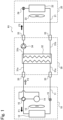
- FIG 1 is a schematic circuit diagram showing a typical example of the configuration of a refrigeration apparatus according to Embodiment 1 of the present invention.
- a refrigeration apparatus includes: a first refrigeration cycle including an outdoor heat exchanger, a compressor, an expansion mechanism, and first piping by which the outdoor heat exchanger, the compressor, and the expansion mechanism are connected to allow a first working medium to circulate through the outdoor heat exchanger, the compressor, and the expansion mechanism; a second refrigeration cycle including an indoor heat exchanger, a refrigerant pump, and second piping by which the indoor heat exchanger and the refrigerant pump are connected to allow a second working medium to circulate through the indoor heat exchanger and the refrigerant pump; and a relay heat exchanger located between the first refrigeration cycle and the second refrigeration cycle to effect heat exchange between the first refrigeration cycle and the second refrigeration cycle.
- the refrigeration apparatus includes an outdoor unit located outdoors and including the first refrigeration cycle.
- the refrigeration apparatus includes an indoor unit located indoors and including at least the indoor heat exchanger and the second piping of the second refrigeration cycle.
- the refrigeration apparatus includes a relay unit independent of the outdoor unit and the indoor unit and including at least the relay heat exchanger and the refrigerant pump. At least a flammable refrigerant is used as a refrigerant component of the first working medium, and at least a fluoroolefin is used as a refrigerant component of the second working medium.
- the relay unit which is independent of the outdoor unit including the first refrigeration cycle and the indoor unit including part of the second refrigeration cycle, is located between the outdoor unit and the indoor unit.
- the second refrigeration cycle includes the refrigerant pump but does not include any compressor.
- the refrigerant pump does not use any refrigerating machine oil, and this eliminates the possibility that a refrigerating machine oil or the like remains in the second piping of the indoor unit including part of the second refrigeration cycle.
- already-existing refrigerant piping can be used with almost no change.
- the first refrigeration cycle which includes the compressor and employs the first working medium containing a flammable refrigerant as a main component, is included in the outdoor unit.
- the second refrigeration cycle which employs the second working medium containing a fluoroolefin as a main refrigerant component, is included in part in the indoor unit and in part in the relay unit.
- the first refrigeration cycle using the flammable refrigerant is reliably separated from the indoor unit by the presence of the relay unit.
- the presence of the relay unit can further reduce the impact of the use of the flammable refrigerant.
- any fluoroolefin in the first working medium circulating in the first refrigeration cycle including the compressor Fluoroolefins are likely to undergo disproportionation under high-temperature and high-pressure conditions such as those in the compressor.
- the non-use of any fluoroolefin as a refrigerant component of the first working medium eliminates the need to take measures against disproportionation in the first refrigeration cycle.
- the second working medium containing a fluoroolefin as a main component circulates in the second refrigeration cycle which does not include any compressor.
- the refrigerant pump does not produce high-temperature and high-pressure conditions when pumping the second working medium, and can thus be expected to have substantially no risk of causing disproportionation of the fluoroolefin. As such, the second refrigeration cycle need not be prepared against disproportionation either.
- each of the refrigeration cycles can operate well, and already-existing refrigerant piping can be used in the indoor-side refrigeration cycle.
- a refrigeration apparatus R1 shown in FIG 1 is a typical example of a configuration according to Embodiment 1.
- the refrigeration apparatus R1 is configured as an air conditioner.
- the refrigeration apparatus R1 according to Embodiment 1 includes an outdoor unit 10, an indoor unit 20, and a relay unit 30.
- the outdoor unit 10 includes first piping 11, an outdoor heat exchanger 12, an outdoor blower 13, a compressor 14, an expansion valve 15, a four-way valve 16, etc.
- the indoor unit 20, as shown by a dashed box in FIG 1 like the outdoor unit 10, includes second piping 21, an indoor heat exchanger 22, an indoor blower 23, a refrigerant flow regulating valve 24, etc.
- the relay unit 30 includes first relay piping 31a, second relay piping 31b, a relay heat exchanger 32, piping connection portions 33, a refrigerant pump 34, etc.
- the first piping 11 of the outdoor unit 10 and the first relay piping 31a of the relay unit 30 are connected via the piping connection portions 33.
- the compressor 14, one of the piping connection portions 33, the relay heat exchanger 32, another of the piping connection portions 33, the expansion valve 15, and the outdoor heat exchanger 12 are arranged in this order and serially connected in a loop by the first piping 11 and the first relay piping 31a, with the four-way valve 16 between the compressor 14 and the one piping connection portion 33 or the outdoor heat exchanger 12.
- the connected components and the connecting piping constitute a first refrigeration cycle.
- a first working medium circulates in the first refrigeration cycle.
- the first working medium contains at least a flammable refrigerant as a refrigerant component. Since the first refrigeration cycle includes the compressor 14, the first working medium further contains a refrigerating machine oil used in the compressor 14.
- the flammable refrigerant contained in the first working medium is not limited to a particular refrigerant. Examples of flammable refrigerants that can be used in Embodiment 1 include, but are not limited to, saturated hydrocarbons such as propane and mildly flammable refrigerants such as difluoromethane (R-32). Saturated hydrocarbons having a low GWP are preferred for use as the flammable refrigerant.
- the first working medium may contain a non-flammable refrigerant in addition to the flammable refrigerant or may contain a combination of different refrigerants as the flammable refrigerant. That is, the refrigerant component of the first working medium may be a single refrigerant consisting of one flammable refrigerant, may be a refrigerant mixture containing two or more flammable refrigerants, or may be a refrigerant mixture composed of one or more flammable refrigerants and one or more non-flammable refrigerants. Furthermore, the first working medium may contain other components such as additives known in the field of refrigeration cycle working media. The details of the refrigerant component will be described later.
- the compressor 14 compresses the first working medium.
- the outdoor heat exchanger 12 effects heat exchange between the first working medium and outdoor air (outside air).
- the outdoor blower 13 delivers outdoor air toward the outdoor heat exchanger 12.
- the expansion valve 15 is an expansion mechanism that expands the first working medium.
- the discharge outlet and the suction inlet of the compressor 14 are connected to the four-way valve 16.
- the four-way valve 16 switches between different positions to change the flow direction of the first working medium.
- a cooling operation takes place when the four-way valve 16 is in a position to connect the discharge outlet of the compressor 14 to the outdoor heat exchanger 12, while a heating operation takes place when the four-way valve 16 is in a position to connect the discharge outlet of the compressor 14 to the relay heat exchanger 32.
- the cooling and heating operations will be described later.
- FIG 1 the direction in which the first working medium flows during the cooling operation is shown by a black block arrow F1
- the direction in which the first working medium flows during the heating operation is shown by a white block arrow F2.
- the relay unit 30 is connected to the outdoor unit 10 and to the indoor unit 20. Specifically, the second piping 21 of the indoor unit 20 and the second relay piping 31b of the relay unit 30 are connected via the piping connection portions 33.
- the refrigerant pump 34 (relay unit 30), one of the piping connection portions 33, the refrigerant flow regulating valve 24, the indoor heat exchanger 22 (indoor unit 20), another of the piping connection portions 33, and the relay heat exchanger 32 (relay unit 30) are arranged in this order and serially connected in a loop by the second piping 21 (indoor unit 20) and the second relay piping 31b.
- the connected components and the connecting piping constitute a second refrigeration cycle.
- a second working medium circulates in the second refrigeration cycle.
- the second working medium contains at least a fluoroolefin as a refrigerant component.
- the fluoroolefin contained in the second working medium is, for example, but not limited to, 1,1,2-trifluoroethylene (HFO-1123).
- the second working medium may be a single refrigerant consisting of HFO-1123 or may be a refrigerant mixture containing another refrigerant in addition to HFO-1123.
- the second working medium may contain other components such as additives known in the field of refrigeration cycle working media. The details of the refrigerant component will be described later.
- the refrigerant pump 34 pumps the second working medium through the second relay piping 31b and the second piping 21.
- the indoor heat exchanger 22 effects heat exchange between the second working medium and indoor air.
- the indoor blower 23 delivers indoor air toward the indoor heat exchanger 22.
- the second refrigeration cycle does not include any component corresponding to the four-way valve 16 in the first refrigeration cycle. Thus, in the second refrigeration cycle, the second working medium flows and circulates only in one direction. In FIG 1 , the flow direction of the second working medium is shown by a black block arrow F3.
- the relay heat exchanger 32 is a component shared by both the first and second refrigeration cycles.
- the relay heat exchanger 32 effects heat exchange between the first working medium circulating in the first refrigeration cycle mainly included in the outdoor unit 10 and the second working medium circulating in the second refrigeration cycle included in part in the relay unit 30 and in part in the indoor unit 20. It can therefore be said that the first and second refrigeration cycles are thermally connected via the relay heat exchanger 32.
- the refrigeration apparatus R1 is configured as a dual cycle apparatus including two cycles thermally connected via the relay heat exchanger 32 of the relay unit 30, and the relay heat exchanger 32 effects heat exchange between the first and second working media.
- the first and second refrigeration cycles which are independent of each other, can be controlled together as one refrigeration apparatus R1.
- the outdoor heat exchanger 12, the outdoor blower 13, the compressor 14, the expansion valve 15, the four-way valve 16, the indoor heat exchanger 22, the indoor blower 23, the piping connection portions 33, the refrigerant pump 34, and the relay heat exchanger 32 of the refrigeration apparatus R1 are not limited to particular configurations, and any configurations known in the field of refrigeration apparatuses can be suitably employed.
- the outdoor heat exchanger 12 can be regarded as corresponding to a "condenser” of an ordinary refrigeration apparatus.
- the indoor heat exchanger 22 can be regarded as corresponding to an "evaporator” of an ordinary refrigeration apparatus.
- a heat exchanger known as a condenser can be used as the outdoor heat exchanger 12
- a heat exchanger known as an evaporator can be used as the indoor heat exchanger 22.
- Examples of such heat exchangers include, but are not limited to, plate heat exchangers, double pipe heat exchangers, and shell-and-tube heat exchangers.
- a known heat exchanger can be suitably used as the relay heat exchanger 32.
- the relay heat exchanger 32 effects heat exchange between the first and second working media unlike the outdoor heat exchanger 12 or indoor heat exchanger 22 which effects heat exchange between a corresponding one of the working media and air (outdoor air or indoor air).
- the type of the heat exchanger used as the relay heat exchanger 32 can be selected depending on the types of the first and second working media.
- the first working medium contains a flammable refrigerant as a main refrigerant component
- the second working medium contains a fluoroolefin as a main refrigerant component.
- a plate heat exchanger can be used as the relay heat exchanger 32.
- a known hermetic refrigerant compressor can be suitably used as the compressor 14.
- the hermetic refrigerant compressor may be any kind of compressor such as a reciprocating, rotary, scroll, or screw compressor.
- the electric element of the refrigerant compressor may have the same configuration as any known motor and may be an outer rotor-type motor or an inner rotor-type motor.
- the refrigerant pump 34 may have any known configuration used for pumping of refrigerants (refrigeration cycle working media).
- Typical examples of the pump include: reciprocating positive displacement pumps such as piston pumps, plunger pumps, and diaphragm pumps; rotary positive displacement pumps such as gear pumps and screw pumps; centrifugal pumps such as multistage pumps, vertical pumps, self-sucking pumps, canned pumps, and magnet pumps; and cascade pumps.
- the refrigerant pump 34 is not limited to a particular configuration and may be configured in any way that allows the refrigerant pump 34 to successfully pump and circulate the second working medium through the second refrigeration cycle.
- the refrigerant pump 34 may be configured to include a motor located to avoid contact with the second working medium.
- Disproportionation of fluoroolefins is likely to occur under high-temperature and high-pressure conditions such as those in the compressor 14. Furthermore, the occurrence of electric discharge in the compressor 14 would notably increase the likelihood of disproportionation.
- the refrigerant pump 34 can pump the second working medium without producing high-temperature and high-pressure conditions and has little risk of causing disproportionation of the fluoroolefin.
- the expansion valve 15 used may be a thermostatic expansion valve, an electronic expansion valve, or any other expansion mechanism known in the field of refrigeration cycles.
- the four-way valve 16 the outdoor blower 13, the indoor blower 23, etc., various configurations known in the field of refrigeration apparatuses can be suitably employed.
- the piping connection portions 33 are not limited to a particular configuration either, and any configuration known in the field of refrigeration apparatuses or refrigeration cycles can be suitably employed.
- the piping connection portions 33 need not be those in which the pipes are united together by welding or any other process but may be those in which the pipes are connected by means of joints (couplings for refrigerant piping).
- the latter configuration can enhance the efficiency in replacement of a hitherto-used refrigerant component having a high GWP (such as an HCFC or HFC) by a fluoroolefin.
- the following will describe exemplary operations of the refrigeration apparatus R1 described above.
- a cooling operation will be described first.
- the first refrigeration cycle mainly included in the outdoor unit 10
- the first working medium compressed by the compressor 14 and having a high temperature and a high pressure is delivered to the outdoor heat exchanger 12 through the four-way valve 16 (the direction of the arrow F1).
- the outdoor heat exchanger 12 allows the first working medium to exchange heat with outdoor air (outside air) delivered by the outdoor blower 13 and thus turn into a high-pressure, middle-to-high temperature liquid, which is delivered to the expansion valve 15.
- the first working medium is expanded by the expansion valve 15 and turns into a low-pressure, low-temperature gas-liquid mixture, which is delivered to the relay heat exchanger 32 through the first piping 11 of the outdoor unit 10, one of the piping connection portions 33, and the first relay piping 31a of the relay unit 30.
- the relay heat exchanger 32 allows the first working medium to exchange heat with the second working medium circulating in the second refrigeration cycle and thus turn into a low-pressure, middle-to-low temperature gas, which is sucked into the suction inlet of the compressor 14 through the four-way valve 16.
- the second working medium is pumped by the refrigerant pump 34 to the relay heat exchanger 32 (the direction of the black block arrow F3).
- the relay heat exchanger 32 effects heat exchange between the first and second working media.
- the second working medium is cooled by the first working medium having a low temperature and a low pressure and then delivered to the indoor heat exchanger 22 through the second relay piping 31b of the relay unit 30, one of the piping connection portions 33, and the second piping 21 of the indoor unit 20.
- the refrigerant flow regulating valve 24 Since the refrigerant flow regulating valve 24 is located upstream of the indoor heat exchanger 22 in the flow direction of the second working medium, the flow rate of the second working medium flowing into the indoor heat exchanger 22 is regulated by the refrigerant flow regulating valve 24.
- the indoor heat exchanger 22 having received the second working medium allows the second working medium to exchange heat with indoor air delivered by the indoor blower 23.
- the indoor air is cooled by the second working medium and cools the indoor space.
- the second working medium coming out of the indoor heat exchanger 22 returns to the refrigerant pump 34 through the second piping 21, another of the piping connection portions 33, and the second relay piping 31b.
- the first working medium compressed by the compressor 14 and having a high temperature and a high pressure is delivered to the relay heat exchanger 32 through the four-way valve 16, the first piping 11 of the outdoor unit 10, one of the piping connection portions 33, and the first relay piping 31a of the relay unit 30 (the direction of the arrow F2).
- the relay heat exchanger 32 effects heat exchange between the first working medium and the second working medium circulating in the second refrigeration cycle, thus turning the first working medium into a high-pressure, middle-to-low-temperature liquid, which is delivered to the expansion valve 15.
- the first working medium is expanded by the expansion valve 15 and turns into a low-temperature, low-pressure gas-liquid mixture, which is delivered to the outdoor heat exchanger 12.
- the outdoor heat exchanger 12 allows the first working medium to exchange heat with outdoor air delivered by the outdoor blower 13 and thus turn into a low-pressure, middle-to-low-temperature gas, which is sucked into the suction inlet of the compressor 14.
- the second working medium is pumped by the refrigerant pump 34 to the relay heat exchanger 32.
- the relay heat exchanger 32 effects heat exchange between the first and second working media.
- the second working medium is heated by the first working medium having a high temperature and a high pressure, and the heated second working medium is delivered to the indoor heat exchanger 22 through the second relay piping 31b of the relay unit 30, one of the piping connection portions 33, and the second piping 21 of the indoor unit 20.
- the indoor heat exchanger 22 allows the second working medium to exchange heat with indoor air delivered by the indoor blower 23, and thus the indoor air is heated by the second working medium and heats the indoor space.
- the second working medium coming out of the indoor heat exchanger 22 flows into the refrigerant flow regulating valve 24, by which the flow rate of the second working medium is regulated. After that, the second working medium returns to the refrigerant pump 34 through the second piping 21, another of the piping connection portions 33, and the second relay piping 31b.
- the first refrigeration cycle is included in the outdoor unit 10
- at least the indoor heat exchanger 22 and the second piping 21 of the second refrigeration cycle are included in the indoor unit 20
- at least the relay heat exchanger 32 and the refrigerant pump 34 are included in the relay unit 30.
- At least a flammable refrigerant is used as a refrigerant component of the first working medium
- at least a fluoroolefin is used as a refrigerant component of the second working medium.
- the second refrigeration cycle includes the refrigerant pump 34 but does not include any compressor 14, and the refrigerant pump 34 does not use any refrigerating machine oil. This substantially eliminates the possibility that a refrigerating machine oil, a compound derived from the refrigerating machine, or any other undesired matter remains in the second piping 21 of the indoor unit 20 including part of the second refrigeration cycle.
- a refrigerating machine oil remains in already-existing refrigerant piping in a refrigeration cycle including the compressor 14 using the refrigerating machine oil.
- the already-existing refrigerant piping containing the remaining refrigerating machine oil cannot be used without change, and it is necessary to clean the interior of the refrigerant piping or replace the refrigerant piping entirely.
- the second refrigeration cycle located on the indoor side does not include any compressor 14, the refrigerating machine oil or the like does not enter the second piping 21 located on the indoor side.
- the first refrigeration cycle which includes the compressor 14 and employs the first working medium containing a flammable refrigerant as a main component, is included in the outdoor unit 10.
- the second refrigeration cycle there is no need to use any flammable refrigerant as a refrigerant component.
- the first refrigeration cycle using the flammable refrigerant is reliably separated from the indoor unit 20 by the presence of the relay unit 30.
- the presence of the relay unit 30 can further reduce the impact of the use of the flammable refrigerant.
- the flammable refrigerant contained as a main refrigerant component in the first working medium may be a saturated hydrocarbon. That is, a refrigerant component having a significantly low GWP can be used in the first working medium.
- the relay unit 30 when the relay unit 30 is located outdoors, the whole of the first refrigeration cycle in which the first working medium circulates is located outdoors.
- the refrigerant component used in the second refrigeration cycle most of which is located indoors does not contain any saturated hydrocarbon. The impact of the use of a saturated hydrocarbon which is a flammable refrigerant can be further reduced by the presence of the relay unit 30.
- the first working medium used in the first refrigeration cycle contains a flammable refrigerant as a refrigerant component.
- a typical example of the flammable refrigerant is a saturated hydrocarbon.
- saturated hydrocarbon examples include ethane, n-propane, cyclopropane, n-butane, cyclobutane, isobutane (2-methylpropane), methylcyclopropane, n-pentane, isopentane (2-methylbutane), neopentane (2,2-dimethylpropane), and methylcyclobutane.
- flammable refrigerant examples include hydrofluorocarbons (HFCs) that are classified as A2 refrigerants (flammable) or A2L refrigerants (mildly flammable) according to ASHRAE 34 safety classification (these refrigerants will be referred to as "flammable HFCs" for the sake of convenience).
- HFCs hydrofluorocarbons
- flammable HFCs include difluoromethane (R-32, A2L) and 1,1-difluoroethane (R-152a, A2).
- One of the flammable refrigerants as mentioned above may be used alone, or two or more thereof may be used in any suitable combination.
- the most typical example of the saturated hydrocarbons is n-propane, and the most typical example of the flammable HFCs is R-32.
- the second working medium contains at least a fluoroolefin (fluoroalkene) as a refrigerant component.
- the fluoroolefin is not limited to a particular type, and examples of the fluoroolefin include fluoroethylenes such as 1,1,2-trifluoroethylene (HFO-1123), trans -1,2-difluoroethylene (HFO-1132(E)), cis-1,2-difluoroethylene (HFO-1132(Z)), 1,1-difluoroethylene (HFO-1132a), tetrafluoroethylene (FO-1114, TFE), and monofluoroethylene (HFO-1141); and fluoropropenes such as 1,2,3,3,3-pentafluoropropene (HFO-1225ye), 2,3,3,3-tetrafluoropropene (HFO-1234yf), 1,3,3,3-tetrafluoropropene (HFO)
- fluoroolefins may be used alone as a refrigerant component, or any suitable combination of two or more of the fluoroolefins may be used as a refrigerant component.
- fluoroolefins the fluoroethylenes are suitable for use as a refrigerant component.
- fluoroethylenes 1,1,2-trifluoroethylene (HFO-1123) is particularly suitable for use.
- the second working medium may contain an additional refrigerant component other than fluoroolefins.
- the additional refrigerant component is not limited to a particular refrigerant, and typical examples of the additional refrigerant component include hydrofluorocarbons (HFCs) and natural refrigerants such as carbon dioxide (CO 2 gas), ammonia, hydrocarbons, and nitrogen.
- HFCs include: fluoromethanes such as difluoromethane (R-32) and trifluoromethane (R-23); fluoroethanes such as fluoroethane (R-161), 1,1-difluoroethane (R-152a), 1,1,1-trifluoroethane (R-143a), 1,1,2,2-tetrafluoroethane (R-134), 1,1,1,2-tetrafluoroethane (R-134a), pentafluoroethane (R-125), difluoroethane, and trifluoroethane; fluoropropanes such as 1,1,1,3,3-pentafluoropropane (R-245fa), 1,1,1,2,3,3-hexafluoropropane (R-236ea), 1,1,1,3,3,3-hexafluoropropane (R-236fa), and 1,1,1,2,3,3,3-heptafluoropropane
- One of the additional refrigerants as mentioned above may be used alone, or two or more thereof may be used in any suitable combination.
- R-32 difluoromethane is typically suitable for use.
- the second working medium contains a fluoroolefin. Fluoroolefins are known to undergo disproportionation.
- the second refrigeration cycle in which the second working medium circulates does not include any compressor 14, and the refrigerant pump 34 included in the second refrigeration cycle is a pump which, unlike the compressor 14, does not bring the second working medium into a high-temperature and high-pressure state.
- the refrigerant pump 34 may be configured such that its motor, in which electric discharge could occur, does not contact the second working medium. In the present disclosure, therefore, it is expected that disproportionation of the fluoroolefin contained in the second working medium can be substantially prevented.
- the second working medium may contain a disproportionation inhibitor that inhibits disproportionation of the fluoroolefin.
- disproportionation inhibitor examples include, but are not limited to: saturated hydrocarbons with two to five carbon atoms; haloalkanes with one to four carbon atoms other than haloalkanes all the halogen atoms of which are fluorine; and fluoroalkanes with one to three carbon atoms and a boiling point of 0°C or lower.
- a saturated hydrocarbon used as a disproportionation inhibitor will be referred to as a "disproportionation-inhibiting alkane”
- a haloalkane used as a disproportionation inhibitor will be referred to as a “disproportionation-inhibiting haloalkane”
- a fluoroalkane used as a disproportionation inhibitor will be referred to as a “disproportionation-inhibiting fluoroalkane”.
- the disproportionation-inhibiting alkane used as a disproportionation inhibitor in the present disclosure may be a saturated hydrocarbon (alkane) with two to five carbon atoms, and specific examples of such a saturated hydrocarbon include ethane, n-propane, cyclopropane, n-butane, cyclobutane, isobutane (2-methylpropane), methylcyclopropane, n-pentane, isopentane (2-methylbutane), neopentane (2,2-dimethylpropane), and methylcyclobutane.
- alkane alkane
- specific examples of such a saturated hydrocarbon include ethane, n-propane, cyclopropane, n-butane, cyclobutane, isobutane (2-methylpropane), methylcyclopropane, n-pentane, isopentane (2-methylbutane), neopent
- All of the above-mentioned saturated hydrocarbons are gaseous at normal temperature (n-pentane and methylcyclobutane have the highest boiling point which is about 36°C, and the other hydrocarbons have a boiling point lower than 36°C), and any of the saturated hydrocarbons can be mixed well with the refrigerant component of the second working medium.
- Any saturated hydrocarbon with six or more carbon atoms is not preferred because such a saturated hydrocarbon is liquid at normal temperature and difficult to mix with the refrigerant component of the second working medium.
- GWP global warming potential
- cyclopentane has a boiling point of 49°C and is liquid at normal temperature; however, cyclopentane may be used as a disproportionation inhibitor in the present disclosure.
- the disproportionation-inhibiting haloalkane used as a disproportionation inhibitor in the present disclosure may be any haloalkane with one to four carbon atoms other than haloalkanes all the halogen atoms of which are fluorine.
- Specific examples of the disproportionation-inhibiting haloalkane include halomethanes (halogenated methanes) which have one carbon atom, haloethanes (halogenated ethanes) which have two carbon atoms, halopropanes (halogenated propanes) which have three carbon atoms, and halobutanes (halogenated butanes) which have four carbon atoms.
- Haloalkanes all the halogen substituents of which are fluorine are considered to fall within the scope of the disproportionation-inhibiting fluoroalkane as described later.
- the disproportionation-inhibiting haloalkane used may be one haloalkane selected from halomethanes, haloethanes, halopropanes, and halobutanes, or two or more haloalkanes selected from these disproportionation-inhibiting haloalkanes may be used in any suitable combination.
- two or more haloalkanes selected is intended to mean not only that two or more disproportionation-inhibiting haloalkanes differing in the number of carbon atoms may be selected (for example, a combination of a halomethane and a halomethane) but also that two or more disproportionation-inhibiting haloalkanes having the same number of carbon atoms and having different halogen substituents may be selected (for example, a combination of a first haloethane and a second haloethane different from the first haloethane).
- the halobutane may have a linear structure or may have a branched structure (a structure having the same carbon skeleton as isobutane or 2-methylpropane).
- the disproportionation-inhibiting haloalkane may have a structure represented by the following formula (1).
- X is a halogen atom selected from the group consisting of fluorine (F), chlorine (Cl), bromine (Br), and iodine (I),
- F fluorine
- Cl chlorine
- Br bromine
- I iodine
- p is an integer of 1 or 2
- q is an integer of 0 or more
- r is an integer of 1 or more
- the sum of q and r is 2p + 2
- the halogen atoms X are the same or different when r is 2 or more.
- any haloalkane which is represented by the formula (1) but which contains only F as the halogen atom(s) X is excluded from the scope of the disproportionation-inhibiting haloalkane. This is because any disproportionation-inhibiting haloalkane which contains only F as the halogen atom(s) X corresponds to a fluoromethane with one carbon atom or a fluoroethane with two carbon atoms, both of which fall within the scope of the disproportionation-inhibiting fluoroalkane described later.
- the halogen atom X may be at least one of F, Cl, Br, and I as stated above and is preferably at least I.
- the halogen atoms X preferably include at least F and I.
- some disproportionation-inhibiting haloalkanes represented by the formula (1) are compounds having a relatively high ozone depletion potential (ODP) and/or a relatively high global warming potential (GWP).
- a disproportionation-inhibiting haloalkane added to the second working medium can effectively inhibit disproportionation of the fluoroolefin or retard rapid progress of disproportionation of the fluoroolefin even when the amount of the added disproportionation-inhibiting haloalkane is relatively small.
- a disproportionation-inhibiting haloalkane is used in combination with another disproportionation inhibitor such as a disproportionation-inhibiting alkane, the total amount of the disproportionation inhibitors added is sufficiently small relative to the total amount of the first working medium.
- the use of a disproportionation-inhibiting haloalkane does not cause any significant impact on the environment even when the disproportionation-inhibiting haloalkane has a relatively high ODP or GWP.
- disproportionation-inhibiting haloalkanes represented by the formula (1) include, but are not limited to: halomethanes such as (mono)iodomethane (CH 3 I), diiodomethane (CH 2 I 2 ), dibromomethane (CH 2 Br 2 ), bromomethane (CH 3 Br), dichloromethane (CH 2 Cl 2 ), chloroiodomethane (CH 2 ClI), dibromochloromethane (CHBr 2 Cl), tetraiodomethane (CI 4 ), carbon tetrabromide (CBr 4 ), bromotrichloromethane (CBrCl 3 ), dibromodichloromethane (CBr 2 Cl 2 ), tribromofluoromethane (CBr 3 F), fluorodiiodomethane (CHFI 2 ), difluorodiiodomethane (CF 2 I 2 ), dibromodifluoromethane (CHFI
- disproportionation-inhibiting haloalkanes may be used alone, or two or more thereof may be used in any suitable combination.
- disproportionation-inhibiting haloalkanes at least one selected from the group consisting of diiodomethane (CH 2 I 2 ), difluorodiiodomethane (CF 2 I 2 ), trifluoroiodomethane (CF 3 I), difluoroiodomethane (CHF 2 I), 1-bromo-2-iodo-tetrafluoroethane (CF 2 BrCF 2 I), and 1,1,1-trifluoro-2-iodoethane (CF 3 CH 2 I) is particularly preferred in terms of factors such as availability, ODP value, and handleability.
- the disproportionation-inhibiting fluoroalkane used as a disproportionation inhibitor in the present disclosure may be a fluoroalkane with one to three carbon atoms and a boiling point of 0°C or lower. Any fluoroalkane with one to three carbon atoms can be said to be an alkane which has one to three carbon atoms and at least one of whose hydrogen atoms is substituted by fluorine.
- fluoroalkanes particularly typical compounds are fluoropropanes.
- the fluoropropane that can be used as the disproportionation-inhibiting fluoroalkane in the present disclosure may be any alkane which has three carbon atoms (namely, propane), one or more of whose hydrogen atoms are substituted by fluorine atoms, and which has a boiling point of 0°C or lower.
- 1-fluoropropane and 2-fluoropropane compounds derived from substitution of one hydrogen atom of propane by fluorine
- fluoropropane used as the disproportionation-inhibiting fluoroalkane in the present disclosure is not limited to 1-fluoropropane or 2-fluoropropane.
- any disproportionation-inhibiting fluoroalkane is used as a component of the second working medium together with a fluoroolefin serving as a main refrigerant component of the second working medium. Due to being a refrigeration cycle working medium, the second working medium basically needs to be gaseous in a normal temperature range. For this reason, the disproportionation-inhibiting fluoroalkane used has to have a boiling point of 0°C or lower.
- the second working medium is a refrigerant containing at least a fluoroolefin (fluoroalkene).
- the second working medium may contain an additional refrigerant component such as an HFC and may further contain a disproportionation inhibitor.
- the amount (percentage) of the fluoroolefin, the amount (percentage) of the additional refrigerant component, and the amount (percentage) of the disproportionation inhibitor are not limited to particular values. Amounts (ranges) as known in the art may be employed, or different amounts known in the art may be combined as appropriate.
- the first working medium contains a flammable refrigerant as a main refrigerant component
- the second working medium contains a fluoroolefin as a main refrigerant component.
- the first working medium composed mainly of the flammable refrigerant circulates in the first refrigeration cycle including the compressor 14, while the second working medium composed mainly of the fluoroolefin circulates in the second refrigeration cycle which does not include any compressor 14.
- disproportionation of the fluoroolefin can be substantially prevented.
- the flammable refrigerant circulates mainly in the outdoor unit 10, and the relay unit 30 is located between the indoor unit 20 and the outdoor unit 10. This effectively reduces the possibility that the use of the flammable refrigerant has various impacts on indoor regions.
- Both the first and second working media may contain additives or other components known in the field of refrigeration apparatuses or refrigeration cycles (or the field of refrigeration cycle working media).
- the first working medium which is compressed by the compressor 14 in the first refrigeration cycle, may contain a refrigerating machine oil retained in the compressor 14.
- the first refrigeration cycle is included in the outdoor unit 10
- at least the indoor heat exchanger 22 and the second piping 21 of the second refrigeration cycle are included in the indoor unit 20
- at least the relay heat exchanger 32 and the refrigerant pump 34 are included in the relay unit 30.
- At least a flammable refrigerant is used as a refrigerant component of the first working medium
- at least a fluoroolefin is used as a refrigerant component of the second working medium.
- the second working medium containing a fluoroolefin as a main component circulates in the second refrigeration cycle which does not include any compressor 14.
- the refrigerant pump 34 included in the second refrigeration cycle does not produce high-temperature and high-pressure conditions when pumping the second working medium, and can thus be expected to have substantially no risk of causing disproportionation of the fluoroolefin. As such, the second refrigeration cycle need not be prepared against disproportionation either.
- each of the refrigeration cycles can operate well, and already-existing refrigerant piping can be used in the indoor-side refrigeration cycle.
- a fluoroolefin is used as a main refrigerant component in the second refrigeration cycle located on the indoor side.
- the fluoroolefin can achieve high thermal efficiency comparable to that achieved by R-32 which is a conventionally-used HFC refrigerant and has a lower GWP than R-32.
- a fluoroolefin which exhibits the same level of thermal efficiency as HFC refrigerants such as R-32, is used as a refrigerant (second working medium) in the second refrigeration cycle located on the indoor side.
- fluoroolefins are known to have the problem of disproportionation, disproportionation of the fluoroolefin in the second refrigeration cycle can be substantially prevented because the refrigerant pump 34 used for delivery of the second working medium in the second refrigeration cycle does not bring the second working medium into a high-temperature and high-pressure state.
- fluoroolefins are compounds that rarely (or never) undergo disproportionation; however, such compounds tend to be less useful as refrigerant components than other fluoroolefins.
- 1,1,2-trifluoroethylene HFO-1123
- HFO-1123 has high refrigerant performance but is prone to disproportionation.
- the second working medium may further contain a component (disproportionation inhibitor) that inhibits disproportionation.
- a component disproportionation inhibitor
- the addition of such a component can significantly reduce the possibility that disproportionation of the fluoroolefin occurs due to unknown factors or for unexpected reasons, even when the fluoroolefin is HFO-1123 or the like which is prone to disproportionation.
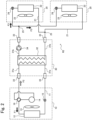
- a refrigeration apparatus R2 shown in FIG 2 is a typical example of a configuration according to Embodiment 2.
- the refrigeration apparatus R2 according to Embodiment 2 includes an outdoor unit 10, an indoor unit 20, and a relay unit 30 like the refrigeration apparatus R1 according to Embodiment 1 described above.
- a first refrigeration cycle is included in the outdoor unit 10
- a second refrigeration cycle is included in part in the indoor unit 20 and in part in the relay unit 30, and the first and second refrigeration cycles are thermally connected by a relay heat exchanger 32.
- the refrigeration apparatus R2 according to Embodiment 2 includes a plurality of indoor units 20. Although FIG 2 depicts two indoor units 20, the refrigeration apparatus R2 according to Embodiment 2 may include three or more indoor units 20. All of the indoor units 20 have basically the same configuration, and each indoor unit 20 includes second piping 21, an indoor heat exchanger 22, an indoor blower 23, a refrigerant flow regulating valve 24, etc.
- the relay heat exchanger 32 included in the relay unit 30 is connected to the second piping 21 of each of the plurality of indoor units 20 via branch portions 25.
- the second relay piping 31b of the relay unit 30 is connected to the plurality of (two) indoor units 20 via piping connection portions 33.
- This connection is similar to that in the refrigeration apparatus R1 according to Embodiment 1 described above, but the difference is that there are the branch portions 25 between the piping connection portions 33 and the second piping 21.
- each branch portion 25 may be located between the second relay piping 31b of the relay unit 30 and the piping connection portions 33.
- each branch portion 25 provides two branches each of which extends from a corresponding one of the piping connection portions 33 toward the second piping 21 of a corresponding one of the indoor units 20.
- each branch portion 25 provides three branches each of which extends toward the second piping 21 of a corresponding one of the indoor units 20.
- the branch portions 25 are not limited to a particular configuration. Any known configuration can be suitably employed such as that using branched pipes or branched couplings commonly known in the field of refrigerant piping.
- the first refrigeration cycle located on the heat source side is included in the single outdoor unit 10 and the relay unit 30 is also a single unit, while the second refrigeration cycle located on the space cooling/heating side is divided into a plurality of indoor units 20 via the relay heat exchanger 32 included in the relay unit 30.
- a plurality of indoor spaces can be cooled or heated using one heat source circuit.
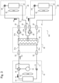
- a refrigeration apparatus R3 shown in FIG 3 is a typical example of a configuration according to Embodiment 3.
- the refrigeration apparatus R3 according to Embodiment 3 includes one outdoor unit 10, one relay unit 30, and a plurality of indoor units 20 (two indoor units 20 in FIG 3 ) like the refrigeration apparatus R2 according to Embodiment 2 described above.
- a first refrigeration cycle is included in the outdoor unit 10
- a second refrigeration cycle is included in part in the indoor unit 20 and in part in the relay unit 30, and the first and second refrigeration cycles are thermally connected by a relay heat exchanger 32.
- the refrigeration apparatus R3 according to Embodiment 3 differs from the refrigeration apparatus R2 according to Embodiment 2 in that there are no branch portions 25 between the relay heat exchanger 32 and the second piping 21 and that the relay heat exchanger 32 is located between one first refrigeration cycle and a plurality of second refrigeration cycles.
- the relay heat exchanger 32 includes: a first working medium flow region through which the first working medium flows and which is connected to the single first refrigeration cycle; and two second working medium flow regions through which the second working medium flows and each of which is connected to a corresponding one of the two second refrigeration cycles, the two second working medium flow regions being opposed to the first working medium flow region and arranged in parallel to each other. The same goes for the case where there are three or more second refrigeration cycles.
- the first refrigeration cycle located on the heat source side is included in the single outdoor unit 10 and the relay unit 30 is also a single unit, while on the space cooling/heating side there are the plurality of second refrigeration cycles, each of which is included in part in a corresponding one of the plurality of indoor units 20.
- the refrigeration apparatus R3 can cool or heat a plurality of indoor spaces using one heat source circuit.
- a refrigeration apparatus R includes a plurality of indoor units 20
- whether to employ the configuration of Embodiment 2 which includes the branch portions 25 or the configuration of Embodiment 3 which includes the relay heat exchanger 32 that can effect heat exchange between one first refrigeration cycle and a plurality of second refrigeration cycles can be chosen as appropriate depending on the conditions under which the refrigeration apparatus R is installed (the state of a building, rooms, or the like for which the refrigeration apparatus R is installed).
- the configuration disclosed in Embodiment 2 and the configuration disclosed in Embodiment 3 may be combined.
- the plurality of indoor units 20 have the same configuration.
- the indoor units 20 may have different configurations depending on, for example, the conditions of rooms in which the indoor units 20 are installed.
- FIG 2 or 3 only shows basic components such as the second piping 21, the indoor heat exchanger 22, the indoor blower 23, and the refrigerant flow regulating valve 24 for each indoor unit 20.
- components other than the basic components of each indoor unit 20 may be customized depending on the conditions under which the indoor unit 20 is installed.
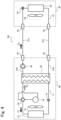
- a refrigeration apparatus R4 shown in FIG 4 is a typical example of a configuration according to Embodiment 4. As shown in FIG 4 , the refrigeration apparatus R4 according to Embodiment 4 includes an integral outdoor unit 40 and an indoor unit 20.
- the integral outdoor unit 40 In the integral outdoor unit 40, the outdoor unit 10 and the relay unit 30 of the refrigeration apparatus R1 according to Embodiment 1 described above are integrated together.
- the integral outdoor unit 40 is located outdoors. Specifically, as shown by a dashed line in FIG 4 , the integral outdoor unit 40 includes first piping 11, an outdoor heat exchanger 12, an outdoor blower 13, a compressor 14, an expansion valve 15, a four-way valve 16, second relay piping 31b, a relay heat exchanger 32, piping connection portions 33, a refrigerant pump 34, etc.
- the compressor 14, the relay heat exchanger 32, the expansion valve 15, and the outdoor heat exchanger 12 are arranged in this order and serially connected in a loop by the first piping 11, with the four-way valve 16 between the compressor 14 and the relay heat exchanger 32 or the outdoor heat exchanger 12.
- the connected components and the connecting piping constitute a first refrigeration cycle. That is, the integral outdoor unit 40 is configured in almost the same manner as the combination of the outdoor unit 10 and the relay unit 30 in the refrigeration apparatus R1 according to Embodiment 1 described above, except that the integral outdoor unit 40 does not include first relay piping 31a and piping connection portions 33 connecting the first relay piping 31a to the first piping 11.
- the configurations of the indoor unit 20 and the second refrigeration cycle in the refrigeration apparatus R4 according to Embodiment 4 are substantially identical to those in the refrigeration apparatus R1 according to Embodiment 1 described above. The difference is that the integral outdoor unit 40 and the indoor unit 20 are connected by connection piping 31c via piping connection portions 33.
- the connection piping 31c has the same configuration as the first piping 11, the second piping 21, and the second relay piping 31b.
- the indoor unit 20 includes the second piping 21, the indoor heat exchanger 22, the indoor blower 23, the refrigerant flow regulating valve 24, etc., and the refrigerant pump 34 (integral outdoor unit 40), two of the piping connection portions 33, the indoor heat exchanger 22 (indoor unit 20), the other two of the piping connection portions 33, and the relay heat exchanger 32 (integral outdoor unit 40) are arranged in this order and serially connected in a loop by the second piping 21 (indoor unit 20), the connection piping 31c, and the second relay piping 31b to constitute the second refrigeration cycle.
- the first refrigeration cycle which uses a flammable refrigerant can be included in the single integral outdoor unit 40 located outdoors.
- the outdoor unit 10 and the relay unit 30 are independent of each other.
- the refrigeration apparatus R1 cannot provide the advantage of eliminating the need for on-site refrigerant charging process.
- the refrigeration apparatus R1 is advantageous in that the outdoor unit 10 and the relay unit 30 can be individually placed at suitable locations and therefore that there is a lot of flexibility in installing the refrigeration apparatus R1.
- the refrigeration apparatus R4 according to Embodiment 4 includes only one indoor unit 20.
- the refrigeration apparatus R4 may include a plurality of indoor units 20 like the refrigeration apparatus R2 or R3 according to Embodiment 2 or 3 described above.
- the refrigeration apparatus R4 may employ a configuration including branch portions 25 like the refrigeration apparatus R2 according to Embodiment 2 described above.
- the refrigeration apparatus R4 may employ a configuration including a relay heat exchanger 32 that can effect heat exchange between one first refrigeration cycle and a plurality of second refrigeration cycles.
- a refrigeration apparatus R5 shown in FIG 5 is a typical example of a configuration according to Embodiment 5.
- the refrigeration apparatus R5 according to Embodiment 5 includes an integral outdoor unit 40 and one indoor unit 20 like the refrigeration apparatus R4 according to Embodiment 4 described above. The difference is that, as shown in FIG 5 , the integral outdoor unit 40 of the refrigeration apparatus R5 according to Embodiment 5 includes a refrigerant tank 42 charged with the first working medium and connected to the second refrigeration cycle.
- third piping 41 branches from second relay piping 31b of the integral outdoor unit 40 (that region of the second relay piping 31b in which a refrigerant pump 34 is not located) to connect the refrigerant tank 42 to the second relay piping 31b.
- a solenoid valve 43 is located between the third piping 41 and the refrigerant tank 42.
- the point at which the third piping 41 is connected to the second relay piping 31b lies between a relay heat exchanger 32 (integral outdoor unit 40) and an indoor heat exchanger 22 (indoor unit 20) in the second refrigeration cycle.
- the refrigerant pump 34 integrated outdoor unit 40
- two piping connection portions 33 a refrigerant flow regulating valve 24
- the indoor heat exchanger 22 indoor unit 20
- the refrigerant pump 34 and the refrigerant flow regulating valve 24 are connected by connection piping 31c via two of the piping connection portions 33, the refrigerant flow regulating valve 24 and the indoor heat exchanger 22 are connected by the second piping 21, the indoor heat exchanger 22 and the relay heat exchanger 32 are connected by the connection piping 31c via the other two of the piping connection portions 33, and the relay heat exchanger 32 and the refrigerant pump 34 are connected by the second relay piping 31b.
- the third piping 41 is connected to that region of the second relay piping 31b to which the refrigerant pump 34 is not connected.
- the refrigeration apparatus R5 can be made ready for use simply by connecting refrigerant piping (the second relay piping 31b in FIG 5 ) of the integral outdoor unit 40 to the second refrigeration cycle (to the second piping 21 of the indoor unit 20 via the connection piping 31c in FIG 5 ) and drawing a vacuum.
- the integral outdoor unit 40 (first refrigeration cycle) can be charged with the first working medium beforehand. As stated above, this makes it unnecessary to perform the process of charging the first refrigeration cycle with the first working medium at the site where the refrigeration apparatus R5 is installed.
- the integral outdoor unit 40 of the refrigeration apparatus R5 includes the refrigerant tank 42 connectable to the second refrigeration cycle.
- the integral outdoor unit 40 placed in position is connected to the second piping 21 of the indoor unit 20 via the connection piping 3 1c, and a vacuum is drawn through the second piping 21.
- the solenoid valve 43 is opened to supply the second working medium from the refrigerant tank 42 to the second refrigeration cycle.
- the refrigeration apparatus R5 according to Embodiment 5 includes only one indoor unit 20.
- the refrigeration apparatus R5 may include a plurality of indoor units 20 like the refrigeration apparatus R2 or R3 according to Embodiment 2 or 3 described above.
- the refrigeration apparatus R5 may employ a configuration including branch portions 25 like the refrigeration apparatus according to Embodiment 2 described above.
- the refrigeration apparatus R5 may employ a configuration including a relay heat exchanger 32 that can effect heat exchange between one first refrigeration cycle and a plurality of second refrigeration cycles.
- a refrigeration apparatus includes: a first refrigeration cycle including an outdoor heat exchanger, a compressor, an expansion mechanism, and first piping by which the outdoor heat exchanger, the compressor, and the expansion mechanism are connected to allow a first working medium to circulate through the outdoor heat exchanger, the compressor, and the expansion mechanism; a second refrigeration cycle including an indoor heat exchanger, a refrigerant pump, and second piping by which the indoor heat exchanger and the refrigerant pump are connected to allow a second working medium to circulate through the indoor heat exchanger and the refrigerant pump; and a relay heat exchanger located between the first refrigeration cycle and the second refrigeration cycle to effect heat exchange between the first refrigeration cycle and the second refrigeration cycle, wherein the refrigeration apparatus includes an outdoor unit located outdoors and including the first refrigeration cycle, an indoor unit located indoors and including at least the indoor heat exchanger and the second piping of the second refrigeration cycle, and a relay unit independent of the outdoor unit and the indoor unit and including at least the relay heat exchanger and the refrigerant pump, at least
- the present invention can be applied widely and suitably in the field of refrigeration apparatuses, in particular the field of refrigeration apparatuses including a refrigeration cycle that includes a compressor and uses a working medium containing a flammable refrigerant or a fluoroolefin.
Landscapes
- Engineering & Computer Science (AREA)
- Chemical & Material Sciences (AREA)
- Physics & Mathematics (AREA)
- Thermal Sciences (AREA)
- Mechanical Engineering (AREA)
- General Engineering & Computer Science (AREA)
- Chemical Kinetics & Catalysis (AREA)
- Combustion & Propulsion (AREA)
- Materials Engineering (AREA)
- Organic Chemistry (AREA)
- Other Air-Conditioning Systems (AREA)
Applications Claiming Priority (2)
| Application Number | Priority Date | Filing Date | Title |
|---|---|---|---|
| JP2022125722 | 2022-08-05 | ||
| PCT/JP2023/027928 WO2024029482A1 (ja) | 2022-08-05 | 2023-07-31 | 冷凍装置 |
Publications (2)
| Publication Number | Publication Date |
|---|---|
| EP4567347A1 true EP4567347A1 (de) | 2025-06-11 |
| EP4567347A4 EP4567347A4 (de) | 2025-11-26 |
Family
ID=89849308
Family Applications (1)
| Application Number | Title | Priority Date | Filing Date |
|---|---|---|---|
| EP23850037.5A Pending EP4567347A4 (de) | 2022-08-05 | 2023-07-31 | Gefriergerät |
Country Status (5)
| Country | Link |
|---|---|
| US (1) | US20260036351A1 (de) |
| EP (1) | EP4567347A4 (de) |
| JP (1) | JPWO2024029482A1 (de) |
| CN (1) | CN119604727A (de) |
| WO (1) | WO2024029482A1 (de) |
Family Cites Families (7)
| Publication number | Priority date | Publication date | Assignee | Title |
|---|---|---|---|---|
| JP2000234813A (ja) | 1999-02-15 | 2000-08-29 | Mitsubishi Electric Corp | 冷凍装置 |
| EP2921801B1 (de) * | 2010-12-03 | 2018-09-19 | Mitsubishi Electric Corporation | Verfahren zum Ersetzen von Teilen für eine Kältekreislaufvorrichtung |
| WO2014097438A1 (ja) * | 2012-12-20 | 2014-06-26 | 三菱電機株式会社 | 空気調和装置 |
| US10605498B2 (en) * | 2014-01-23 | 2020-03-31 | Mitsubishi Electric Corporation | Heat pump apparatus |
| JP6223545B2 (ja) * | 2014-03-17 | 2017-11-01 | 三菱電機株式会社 | 冷凍装置 |
| JP7642305B2 (ja) * | 2019-06-12 | 2025-03-10 | ダイキン工業株式会社 | 冷媒サイクルシステム |
| JP7216151B2 (ja) * | 2020-07-06 | 2023-01-31 | ダイキン工業株式会社 | 冷凍装置 |
-
2023
- 2023-07-31 JP JP2024539141A patent/JPWO2024029482A1/ja active Pending
- 2023-07-31 US US19/101,122 patent/US20260036351A1/en active Pending
- 2023-07-31 WO PCT/JP2023/027928 patent/WO2024029482A1/ja not_active Ceased
- 2023-07-31 EP EP23850037.5A patent/EP4567347A4/de active Pending
- 2023-07-31 CN CN202380056084.8A patent/CN119604727A/zh active Pending
Also Published As
| Publication number | Publication date |
|---|---|
| CN119604727A (zh) | 2025-03-11 |
| US20260036351A1 (en) | 2026-02-05 |
| WO2024029482A1 (ja) | 2024-02-08 |
| JPWO2024029482A1 (de) | 2024-02-08 |
| EP4567347A4 (de) | 2025-11-26 |
Similar Documents
| Publication | Publication Date | Title |
|---|---|---|
| JP6838100B2 (ja) | ヒートポンプにおけるe−1,1,1,4,4,4−ヘキサフルオロ−2−ブテンの使用 | |
| CN102884153B (zh) | 传热流体和其在逆流热交换器中的用途 | |
| US9683157B2 (en) | Heat transfer method | |
| US10035938B2 (en) | Heat transfer fluid replacing R-134a | |
| CN106029823B (zh) | 热循环用工作介质 | |
| US9011711B2 (en) | Heat transfer fluid replacing R-410A | |
| US10308854B2 (en) | Heat-transfer fluids and use thereof in countercurrent heat exchangers | |
| JP7060017B2 (ja) | 熱サイクル用作動媒体、熱サイクルシステム用組成物および熱サイクルシステム | |
| CN115397943B (zh) | 冷冻循环用工作介质和冷冻循环系统 | |
| CN105164228A (zh) | 热循环用工作介质 | |
| EP3783081B1 (de) | Zusammensetzung mit kühlmittel und anwendung davon | |
| CN112585415B (zh) | 空气调节工艺 | |
| EP4567347A1 (de) | Gefriergerät | |
| EP4545875A1 (de) | Gefriergerät | |
| US20250289987A1 (en) | Air conditioner | |
| EP4567086A1 (de) | Kältekreislaufarbeitsmedium und kältekreislaufsystem | |
| JP2025059402A (ja) | 冷凍サイクル装置 | |
| WO2025004888A1 (ja) | 冷凍サイクル用作動媒体および冷凍サイクルシステム | |
| WO2025004880A1 (ja) | 冷凍サイクル用作動媒体および冷凍サイクルシステム | |
| WO2025004885A1 (ja) | 冷凍サイクル用作動媒体および冷凍サイクルシステム | |
| WO2026070778A1 (ja) | 熱サイクル用作動媒体、熱サイクルシステム用組成物、及び熱サイクルシステム | |
| WO2026070777A1 (ja) | 熱サイクル用作動媒体、熱サイクルシステム用組成物、及び熱サイクルシステム |
Legal Events
| Date | Code | Title | Description |
|---|---|---|---|
| STAA | Information on the status of an ep patent application or granted ep patent |
Free format text: STATUS: THE INTERNATIONAL PUBLICATION HAS BEEN MADE |
|
| PUAI | Public reference made under article 153(3) epc to a published international application that has entered the european phase |
Free format text: ORIGINAL CODE: 0009012 |
|
| STAA | Information on the status of an ep patent application or granted ep patent |
Free format text: STATUS: REQUEST FOR EXAMINATION WAS MADE |
|
| 17P | Request for examination filed |
Effective date: 20250305 |
|
| AK | Designated contracting states |
Kind code of ref document: A1 Designated state(s): AL AT BE BG CH CY CZ DE DK EE ES FI FR GB GR HR HU IE IS IT LI LT LU LV MC ME MK MT NL NO PL PT RO RS SE SI SK SM TR |
|
| DAV | Request for validation of the european patent (deleted) | ||
| DAX | Request for extension of the european patent (deleted) | ||
| A4 | Supplementary search report drawn up and despatched |
Effective date: 20251027 |
|
| RIC1 | Information provided on ipc code assigned before grant |
Ipc: F25B 1/00 20060101AFI20251021BHEP Ipc: C09K 5/04 20060101ALI20251021BHEP |
|
| STAA | Information on the status of an ep patent application or granted ep patent |
Free format text: STATUS: THE APPLICATION HAS BEEN WITHDRAWN |