EP4545795A2 - Gebläse-/saugwerkzeuge mit verbessertem gebläseschaufelgeräusch - Google Patents
Gebläse-/saugwerkzeuge mit verbessertem gebläseschaufelgeräusch Download PDFInfo
- Publication number
- EP4545795A2 EP4545795A2 EP24207763.4A EP24207763A EP4545795A2 EP 4545795 A2 EP4545795 A2 EP 4545795A2 EP 24207763 A EP24207763 A EP 24207763A EP 4545795 A2 EP4545795 A2 EP 4545795A2
- Authority
- EP
- European Patent Office
- Prior art keywords
- fan
- blower
- vac
- tool
- blade
- Prior art date
- Legal status (The legal status is an assumption and is not a legal conclusion. Google has not performed a legal analysis and makes no representation as to the accuracy of the status listed.)
- Pending
Links
Images



Classifications
-
- F—MECHANICAL ENGINEERING; LIGHTING; HEATING; WEAPONS; BLASTING
- F04—POSITIVE - DISPLACEMENT MACHINES FOR LIQUIDS; PUMPS FOR LIQUIDS OR ELASTIC FLUIDS
- F04D—NON-POSITIVE-DISPLACEMENT PUMPS
- F04D19/00—Axial-flow pumps
- F04D19/002—Axial flow fans
-
- F—MECHANICAL ENGINEERING; LIGHTING; HEATING; WEAPONS; BLASTING
- F04—POSITIVE - DISPLACEMENT MACHINES FOR LIQUIDS; PUMPS FOR LIQUIDS OR ELASTIC FLUIDS
- F04D—NON-POSITIVE-DISPLACEMENT PUMPS
- F04D25/00—Pumping installations or systems
- F04D25/02—Units comprising pumps and their driving means
- F04D25/06—Units comprising pumps and their driving means the pump being electrically driven
- F04D25/0673—Battery powered
-
- F—MECHANICAL ENGINEERING; LIGHTING; HEATING; WEAPONS; BLASTING
- F04—POSITIVE - DISPLACEMENT MACHINES FOR LIQUIDS; PUMPS FOR LIQUIDS OR ELASTIC FLUIDS
- F04D—NON-POSITIVE-DISPLACEMENT PUMPS
- F04D29/00—Details, component parts, or accessories
- F04D29/26—Rotors specially for elastic fluids
- F04D29/32—Rotors specially for elastic fluids for axial flow pumps
- F04D29/325—Rotors specially for elastic fluids for axial flow pumps for axial flow fans
-
- F—MECHANICAL ENGINEERING; LIGHTING; HEATING; WEAPONS; BLASTING
- F04—POSITIVE - DISPLACEMENT MACHINES FOR LIQUIDS; PUMPS FOR LIQUIDS OR ELASTIC FLUIDS
- F04D—NON-POSITIVE-DISPLACEMENT PUMPS
- F04D29/00—Details, component parts, or accessories
- F04D29/26—Rotors specially for elastic fluids
- F04D29/32—Rotors specially for elastic fluids for axial flow pumps
- F04D29/325—Rotors specially for elastic fluids for axial flow pumps for axial flow fans
- F04D29/326—Rotors specially for elastic fluids for axial flow pumps for axial flow fans comprising a rotating shroud
-
- F—MECHANICAL ENGINEERING; LIGHTING; HEATING; WEAPONS; BLASTING
- F04—POSITIVE - DISPLACEMENT MACHINES FOR LIQUIDS; PUMPS FOR LIQUIDS OR ELASTIC FLUIDS
- F04D—NON-POSITIVE-DISPLACEMENT PUMPS
- F04D29/00—Details, component parts, or accessories
- F04D29/40—Casings; Connections of working fluid
- F04D29/52—Casings; Connections of working fluid for axial pumps
- F04D29/522—Casings; Connections of working fluid for axial pumps especially adapted for elastic fluid pumps
-
- F—MECHANICAL ENGINEERING; LIGHTING; HEATING; WEAPONS; BLASTING
- F04—POSITIVE - DISPLACEMENT MACHINES FOR LIQUIDS; PUMPS FOR LIQUIDS OR ELASTIC FLUIDS
- F04D—NON-POSITIVE-DISPLACEMENT PUMPS
- F04D29/00—Details, component parts, or accessories
- F04D29/66—Combating cavitation, whirls, noise, vibration or the like; Balancing
- F04D29/661—Combating cavitation, whirls, noise, vibration or the like; Balancing especially adapted for elastic fluid pumps
- F04D29/663—Sound attenuation
- F04D29/664—Sound attenuation by means of sound absorbing material
-
- F—MECHANICAL ENGINEERING; LIGHTING; HEATING; WEAPONS; BLASTING
- F04—POSITIVE - DISPLACEMENT MACHINES FOR LIQUIDS; PUMPS FOR LIQUIDS OR ELASTIC FLUIDS
- F04D—NON-POSITIVE-DISPLACEMENT PUMPS
- F04D29/00—Details, component parts, or accessories
- F04D29/66—Combating cavitation, whirls, noise, vibration or the like; Balancing
- F04D29/661—Combating cavitation, whirls, noise, vibration or the like; Balancing especially adapted for elastic fluid pumps
- F04D29/666—Combating cavitation, whirls, noise, vibration or the like; Balancing especially adapted for elastic fluid pumps by means of rotor construction or layout, e.g. unequal distribution of blades or vanes
Definitions
- the present disclosure relates generally to outdoor tools such as blowers, vacuums and/or combined blower / vacuums, and more particularly, to improved fan blade noise in such tools.
- blowers such as blowers, vacuums, and combined blower / vacuums (collectively “blower/vac tools") are commonly used to concentrate debris, e.g., leaves, using a blowing function and/or collect debris using a sucking function. Homeowners frequently utilized such blowers to clean their yards and outdoor spaces.
- blower/vac tools being powered by a battery power source are particularly desirable due to their portability.
- improvements in various aspects of blower/vac tools, and particularly handheld blower/vac tools are desired.
- blower/vac tools One issue with known blower/vac tools is the noise level that is generated by the fan assembly, and particularly, the fan blase noise, of the blower/vac tool during operation.
- the most sensitive range of human hearing is generally between 2-6 KHz due to the alignment of the natural frequency of the ear's auditory canal, while frequencies between 8-12 KHz have significantly lower human hearing sensitivity, and frequencies of 16-20 KHz or greater are inaudible to humans.
- typical fan blade pass frequency for axial fans in leaf blowers is generally between 2.5-4 KHz, which is directly within the most sensitive range of human hearing.
- blower/vac tools are desired in the art.
- a blower/vac tool with reduced fan blade noise would be advantageous.
- a blower/vacuum tool in accordance with one embodiment, includes a main body extending between a first end and a second end defining an airflow conduit therethrough; and a fan assembly.
- the fan assembly includes an axial fan having a number of fan blades ( n b ), and a motor rotatably connected to the fan.
- Blade Solidity c / s
- c is the length of the chord line of the fan blades
- s 2 ⁇ r m / n b
- r m is the mean radius of the fan blades.
- a blower/vacuum tool in accordance with another embodiment, includes a main body extending between a first end and a second end defining an airflow conduit therethrough; and a fan assembly.
- the fan assembly includes an axial fan having a number of fan blades ( n b ), and a motor rotatably connected to the fan.
- RPM rotations per minute
- BPF blade pass frequency
- the terms “first”, “second”, and “third” may be used interchangeably to distinguish one component from another and are not intended to signify location or importance of the individual components.
- the singular forms “a,” “an,” and “the” include plural references unless the context clearly dictates otherwise.
- the terms “coupled,” “fixed,” “attached to,” and the like refer to both direct coupling, fixing, or attaching, as well as indirect coupling, fixing, or attaching through one or more intermediate components or features, unless otherwise specified herein.
- the terms “comprises,” “comprising,” “includes,” “including,” “has,” “having” or any other variation thereof, are intended to cover a non-exclusive inclusion.
- a process, method, article, or apparatus that comprises a list of features is not necessarily limited only to those features but may include other features not expressly listed or inherent to such process, method, article, or apparatus.
- "or" refers to an inclusive- or and not to an exclusive- or. For example, a condition A or B is satisfied by any one of the following: A is true (or present) and B is false (or not present), A is false (or not present) and B is true (or present), and both A and B are true (or present).
- the present invention is directed to a blower/vacuum tool having a fan assembly that generated reduced noise during operation.
- the fan assembly includes an axial fan and a motor.
- the axial fan including the number and size of fan blades, and the operational characteristics of the motor, including rotational speed, are optimized to reduce audible noise generated in the sensitive range of human hearing, i.e., about 2-6 KHz, by increasing the blade pass frequency of the fan assembly to frequency greater than 6 KHz.
- FIG. 1 illustrates a side view of a blower/vac tool 100 in accordance with an exemplary embodiment.
- the blower/vac tool 100 is configured to generate airflow along an airflow conduit 106 extending between a first end 102, e.g., an air inlet, and a second end 104, e.g., an air outlet, of the blower/vac tool 100.
- the airflow conduit 106 may include a tube as shown.
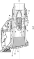
- a housing 108 e.g., a main body of the blower/vac tool 100, may at least partially enclose components of the blower/vac tool 100 such as an airflow generation assembly 110 including a fan 112 and a motor 114 that drives the fan 112, as well as various other components.
- airflow generation assembly 110 may be disposed between the first end 102 and the second end 104 of the airflow conduit 106.
- Power to operate the airflow generation assembly 110 may be provided by a suitable power source such as one or more batteries 116 removably coupled to the housing 108.
- the blower/vac tool 100 may be provided as a standard handheld blower/vac tool having a cordless battery powered power source.
- the blower/vac tool may include a corded electric power source and/or a gas power source.
- a blower/vac tool in accordance with the present disclosure may be a handheld blower/vac tool as shown, or may be provided as a backpack blower/vac tool (not shown) adapted to be worn on a user's back.
- the blower/vac tool may be a blower which utilizes a blowing function, e.g., where airflow is generated from the first end 102 as an inlet to the second end 104 as an outlet.
- the blower/vac tool may be a vacuum which utilizes a sucking function, e.g., where airflow is generated from the second end 104 as an inlet to the first end 102 as an outlet.
- the blower/vac tool may be a combination blower / vacuum which can alternate between utilizing a blowing function and a sucking function.
- the fan 112 includes a hub 130 and a plurality of blades 132.
- the hub 130 may have a generally circular cross-sectional shape and may extend along the motor axis 120.
- the motor shaft 122 is coupled to the hub 130 and/or a fan drive shaft 134 to enable transmission of rotation from the motor 114 to the hub 130 or the fan drive shaft 134 and ultimately to the blades 132.
- each respective fan blade 132 extends radially away from the hub 130.
- Each blade 132 extends from a root 140 and terminates at a tip end 142, and has a first face 144 and a second face 146 opposite the first face 144.
- the root 140 contacts the hub 130 of the fan 112.
- the tip end 142 contacts the hub 130 at a different angular position around the circumference of the hub 130 than the root 140. In another embodiment (not shown), the tip end 142 may contact an adjacent blade 132 of the fan 112.
- the fan 112 may have an inner radius r h defined by a radius of the hub 130, and an outer radius r t defined by a radius of the fan at the tip 142 of the blades.
- the fan 112 may include any suitable number of fan blades (also referred to herein as n b ), as further described below.
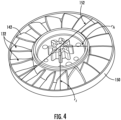
- FIG. 4 illustrates an embodiment of the fan 112 that may include an outer ring 150 surrounding the fan blades 132.
- the outer ring 150 may contact the tip end 142 of one or more of the fan blades 132, e.g., all of the fan blades 132. In this manner, during operation of the blower/vac 10, the outer ring 150 may rotate with rotation of the axial fan 112 and the motor 114.
- the outer ring 150 may have an inner diameter 152 equal to 2 r t .
- the inner diameter 152 may be generally equal to an inner diameter of the first end 102 and/or an inner diameter of the second end 104.
- the inner diameter 152 may be generally equal to both an inner diameter of the first end 102 and an inner diameter of the second end 104.
- the longitudinal axis 124 may extend through a center point of the first end 102, a center point of the outer ring 150, and a center point of the second end 104. In this manner, the airflow conduit may have a generally constant diameter along the length of the airflow conduit 106, thereby reducing disruptions to the flow within the airflow conduit.
- the blade pass frequency of the blower/vac tool 10 may correspond to the sound frequency generated by the axial fan of the tool 10.
- the number of blades, also referred to herein as n b and the rotational speed of the fan may directly influence the sound frequency generated by the blower/vac 10.
- n b the number of blades, also referred to herein as n b
- the rotational speed of the fan may directly influence the sound frequency generated by the blower/vac 10.
- n b the number of blades
- the present inventors have found that achieving a higher blade pass frequency may therefore reduce the audible noise generated by the blower/vac tool 10.
- the present inventors have found that to achieve a higher blade pass frequency above 6 KHz and therefore reduce audible noise generated, the motor rotational speed may be increased, the number of fan blades 132 may be increased, or both the motor rotational speed and the number of fan blades 132 may be increased.
- the motor may be configured to rotate at a rotational speed of between about 21000 - 38000 RPM.
- a rotational speed of between about 21000 - 38000 RPM.
- the present inventors have found that providing a blower/vac 10 having a blade pass frequency of greater than 6 KHz may be desirable.
- the blower/vac 10 may operate at a rotational motor speed as low as 21000 RPM, the present inventors have found that it may be desirable to implement a fan 112 having at least 17 fan blades 132.
- Blade Solidity is measure of fan blade spacing, which is directly influenced by the number of blades provided on a given fan.
- c is the length of the chord line of the fan blades
- r m is the mean radius of the fan blades.
- the present inventors have found that increasing the Blade Solidity of the fan 112, by increasing the number of blades, may result in a blower/vac 10 having reduced audible noise generated during operation. Further, as the number of blades n b increases, the blade solidity value may increase as well.
- the present inventors have found that ideal noise reduction may be achieved when the fan 112 of the blower/vac 10 satisfies the following conditions: n b is in a range from 17 to 45, the axial fan 112 may have a Blade Solidity in a range from 0.0464 n b ⁇ Blade Solidity ⁇ 0.089 n b .
- the airflow generation assembly 110 of the present invention having an axial fan 112 may be optimized when a dimensionless flow coefficient ⁇ is in a range from about 0.2 to about 0.6.
- the size and speed of the airflow generation assembly 110 are defined as a function of the optimal flow coefficient ⁇ .
- the blower/vac 10 may generate less audible noise while maintaining optimal airflow characteristics, thereby improving the user's overall experience during operation of the blower/vac 10. For instance, reducing the audible noise generated by the blower/vac 10 may be highly desirable to users, particularly for homeowners and other non-professional users. Simultaneously, maintaining optimal airflow characteristics may enable efficient battery life of the blower/vac 10, reducing the need for users to recharge or replace the power source without reducing the power of the airflow generated during operation.
- the housing 108 may include an inlet muffler 160 disposed at the first end 102.
- the inlet muffler 160 may be disposed within the airflow conduit 106 at the first end 102.
- the inlet muffler 160 may include a liner 162 surrounding at least a portion of the airflow conduit 106.
- the liner 162 may comprise noise-absorbing material.
- the noise-absorbing material may be configured to absorb noise in a frequency range of 2-6 KHz in order to reduce the audible noise in the human hearing frequency range.
- the noise-absorbing material may include foam.
- the noise-absorbing material may include foam, such as but not limited to foam/film laminates, such as polyurethane foam.
- the liner 162 may surround an entire circumference of the air conduit 106 and/or may surround one or more portions of the circumference of the air conduit 106.
- a blower/vacuum tool includes a main body extending between a first end and a second end defining an airflow conduit therethrough; and a fan assembly.
- the fan assembly includes an axial fan having a number of fan blades ( n b ), and a motor rotatably connected to the fan.
- the motor operates at a speed of between 21000-38000 rotations per minute (RPM)
- blower/vac tool of any one or more of the embodiments, wherein the plurality of fan blades comprises from 17 to 45 fan blades.
- blower/vac tool of any one or more of the embodiments wherein the axial fan comprises a hub and the plurality of fan blades extend from the hub at a root of each respective fan blade.
- each of the plurality of fan blades terminates at a tip of each respective fan blade, the axial fan further comprising an outer ring in contact with the tip of each respective fan blade.
- blower/vac tool of any one or more of the embodiments wherein the outer ring rotates with rotation of the axial fan.
- the outer ring comprises an inner diameter, wherein the inner diameter of the outer ring is generally equal to an inner diameter of the first end and/or an inner diameter of the second end.
- blower/vac tool of any one or more of the embodiments wherein a longitudinal axis extends through a center point of the first end of the main body, a center point of the outer ring, and a center point of the second end of the main body.
- blower/vac tool of any one or more of the embodiments further comprising an inlet muffler disposed at the first end of the main body, the inlet muffler including a liner comprising noise-absorbing material configured to absorb noise in a frequency range of 2-6 KHz.
- blower/vac tool of any one or more of the embodiments, wherein the noise-absorbing material comprises foam.
- a blower/vacuum tool includes a main body extending between a first end and a second end defining an airflow conduit therethrough; and a fan assembly.
- the fan assembly includes an axial fan having a number of fan blades ( n b ), and a motor rotatably connected to the fan.
- n b is in a range from 17- 45
- each of the fan blades terminates at a tip of each respective fan blade, the axial fan further comprising an outer ring in contact with the tip of each respective fan blade.
- blower/vac tool of any one or more of the embodiments wherein the outer ring rotates with rotation of the axial fan.
- the outer ring comprises an inner diameter, wherein the inner diameter of the outer ring is generally equal to an inner diameter of the first end and/or an inner diameter of the second end.
- blower/vac tool of any one or more of the embodiments wherein a longitudinal axis extends through a center point of the first end of the main body, a center point of the outer ring, and a center point of the second end of the main body.
- blower/vac tool of any one or more of the embodiments further comprising an inlet muffler disposed at the first end of the main body, the inlet muffler including a liner comprising noise-absorbing material configured to absorb noise in a frequency range of 2-6 KHz.
- blower/vac tool of any one or more of the embodiments, wherein the noise-absorbing material comprises foam.
Landscapes
- Engineering & Computer Science (AREA)
- Mechanical Engineering (AREA)
- General Engineering & Computer Science (AREA)
- Structures Of Non-Positive Displacement Pumps (AREA)
Applications Claiming Priority (1)
| Application Number | Priority Date | Filing Date | Title |
|---|---|---|---|
| US202363592473P | 2023-10-23 | 2023-10-23 |
Publications (2)
| Publication Number | Publication Date |
|---|---|
| EP4545795A2 true EP4545795A2 (de) | 2025-04-30 |
| EP4545795A3 EP4545795A3 (de) | 2025-07-09 |
Family
ID=93214098
Family Applications (1)
| Application Number | Title | Priority Date | Filing Date |
|---|---|---|---|
| EP24207763.4A Pending EP4545795A3 (de) | 2023-10-23 | 2024-10-21 | Gebläse-/saugwerkzeuge mit verbessertem gebläseschaufelgeräusch |
Country Status (3)
| Country | Link |
|---|---|
| US (1) | US20250129794A1 (de) |
| EP (1) | EP4545795A3 (de) |
| CN (1) | CN223634938U (de) |
Family Cites Families (13)
| Publication number | Priority date | Publication date | Assignee | Title |
|---|---|---|---|---|
| US6386830B1 (en) * | 2001-03-13 | 2002-05-14 | The United States Of America As Represented By The Secretary Of The Navy | Quiet and efficient high-pressure fan assembly |
| US7168918B2 (en) * | 2004-09-30 | 2007-01-30 | General Electric Company | High performance cooling fan |
| EP3225742B1 (de) * | 2014-11-28 | 2020-02-19 | Positec Power Tools (Suzhou) Co., Ltd | Luftgebläse und blas-/saugvorrichtung |
| EP3626972B1 (de) * | 2018-09-21 | 2023-05-10 | Techtronic Outdoor Products Technology Limited | Elektrisches luftgebläse |
| KR20210137750A (ko) * | 2020-05-11 | 2021-11-18 | 엘지전자 주식회사 | 헤어드라이어 |
| CN119498159A (zh) * | 2020-09-29 | 2025-02-25 | 苏州宝时得电动工具有限公司 | 花园吹风机 |
| US11889794B2 (en) * | 2020-12-30 | 2024-02-06 | Milwaukee Electric Tool Corporation | Handheld blower |
| JP7650200B2 (ja) * | 2021-06-25 | 2025-03-24 | 株式会社やまびこ | 軸流ブロワ |
| US12352274B2 (en) * | 2022-03-21 | 2025-07-08 | Milwaukee Electric Tool Corporation | Axial blower |
| CN217976712U (zh) * | 2022-06-27 | 2022-12-06 | 深圳汝原科技有限公司 | 桨叶、螺旋桨和干燥设备 |
| EP4560140A4 (de) * | 2022-07-18 | 2026-01-14 | Greenworks Jiangsu Co Ltd | Axialgebläse |
| WO2024032375A1 (zh) * | 2022-08-12 | 2024-02-15 | 南京泉峰科技有限公司 | 气流设备及手持式吹风机 |
| US12601357B2 (en) * | 2023-09-20 | 2026-04-14 | Whisper Aero Inc. | Air moving devices, aerodynamic rotor, and methods |
-
2024
- 2024-10-09 US US18/910,083 patent/US20250129794A1/en active Pending
- 2024-10-21 EP EP24207763.4A patent/EP4545795A3/de active Pending
- 2024-10-22 CN CN202422555175.0U patent/CN223634938U/zh active Active
Also Published As
| Publication number | Publication date |
|---|---|
| US20250129794A1 (en) | 2025-04-24 |
| EP4545795A3 (de) | 2025-07-09 |
| CN223634938U (zh) | 2025-12-05 |
Similar Documents
| Publication | Publication Date | Title |
|---|---|---|
| US9131814B2 (en) | Electric blower and electric cleaner using same | |
| JP7389779B2 (ja) | 呼吸補助システム及び呼吸補助システムのための送風機 | |
| CN112303032A (zh) | 具有降噪特征的鼓风机 | |
| US9850915B2 (en) | Power tool | |
| US12288544B2 (en) | Power tool having noise reduction features | |
| US20190136866A1 (en) | Blower impeller for a handheld blower | |
| JP2852106B2 (ja) | 電気掃除機及び電動送風機 | |
| JP2008303793A (ja) | 電動送風機、これを用いた電気掃除機 | |
| US20250129794A1 (en) | Blower / vac tools with improved fan blade noise | |
| US20250180040A1 (en) | Blower | |
| JP2013079625A (ja) | 電動遠心送風機及びこれを用いた電気掃除機 | |
| EP4400726A1 (de) | Lüfterhaube und lüfteranordnung mit lüfterhaube | |
| JP3331878B2 (ja) | 電気掃除機 | |
| US20250127101A1 (en) | Walk-behind blower | |
| JP3888504B2 (ja) | 電動送風機および電気掃除機 | |
| US20090148294A1 (en) | Houseless fan with rotating tip ring as silencer | |
| PH12022050337A1 (en) | Axial fan | |
| JPH0635478A (ja) | 電気掃除機 | |
| JPH07224788A (ja) | 多翼送風機 | |
| JP2011196337A (ja) | 電動送風機装置および電気掃除機 | |
| JPH10176852A (ja) | トンネル換気ファン | |
| CN112032103B (zh) | 叶轮、送风装置以及吸尘器 | |
| JP5012096B2 (ja) | 電動送風機及びそれを用いた電気掃除機 | |
| ES2565217T3 (es) | Procedimiento de medida del ruido de un secador de pelo | |
| JP3573111B2 (ja) | ターボファン |
Legal Events
| Date | Code | Title | Description |
|---|---|---|---|
| PUAI | Public reference made under article 153(3) epc to a published international application that has entered the european phase |
Free format text: ORIGINAL CODE: 0009012 |
|
| STAA | Information on the status of an ep patent application or granted ep patent |
Free format text: STATUS: THE APPLICATION HAS BEEN PUBLISHED |
|
| AK | Designated contracting states |
Kind code of ref document: A2 Designated state(s): AL AT BE BG CH CY CZ DE DK EE ES FI FR GB GR HR HU IE IS IT LI LT LU LV MC ME MK MT NL NO PL PT RO RS SE SI SK SM TR |
|
| PUAL | Search report despatched |
Free format text: ORIGINAL CODE: 0009013 |
|
| AK | Designated contracting states |
Kind code of ref document: A3 Designated state(s): AL AT BE BG CH CY CZ DE DK EE ES FI FR GB GR HR HU IE IS IT LI LT LU LV MC ME MK MT NL NO PL PT RO RS SE SI SK SM TR |
|
| RIC1 | Information provided on ipc code assigned before grant |
Ipc: F04D 29/66 20060101ALI20250603BHEP Ipc: F04D 29/32 20060101ALI20250603BHEP Ipc: F04D 19/00 20060101AFI20250603BHEP |
|
| STAA | Information on the status of an ep patent application or granted ep patent |
Free format text: STATUS: REQUEST FOR EXAMINATION WAS MADE |
|
| 17P | Request for examination filed |
Effective date: 20260109 |