EP4545269A1 - Resin molding apparatus and method for producing resin molded article - Google Patents
Resin molding apparatus and method for producing resin molded article Download PDFInfo
- Publication number
- EP4545269A1 EP4545269A1 EP23830713.6A EP23830713A EP4545269A1 EP 4545269 A1 EP4545269 A1 EP 4545269A1 EP 23830713 A EP23830713 A EP 23830713A EP 4545269 A1 EP4545269 A1 EP 4545269A1
- Authority
- EP
- European Patent Office
- Prior art keywords
- carrier
- molding
- substrate
- conveyance
- conveyance member
- Prior art date
- Legal status (The legal status is an assumption and is not a legal conclusion. Google has not performed a legal analysis and makes no representation as to the accuracy of the status listed.)
- Pending
Links
Images






Classifications
-
- B—PERFORMING OPERATIONS; TRANSPORTING
- B29—WORKING OF PLASTICS; WORKING OF SUBSTANCES IN A PLASTIC STATE IN GENERAL
- B29C—SHAPING OR JOINING OF PLASTICS; SHAPING OF MATERIAL IN A PLASTIC STATE, NOT OTHERWISE PROVIDED FOR; AFTER-TREATMENT OF THE SHAPED PRODUCTS, e.g. REPAIRING
- B29C45/00—Injection moulding, i.e. forcing the required volume of moulding material through a nozzle into a closed mould; Apparatus therefor
- B29C45/17—Component parts, details or accessories; Auxiliary operations
- B29C45/40—Removing or ejecting moulded articles
- B29C45/42—Removing or ejecting moulded articles using means movable from outside the mould between mould parts, e.g. robots
-
- B—PERFORMING OPERATIONS; TRANSPORTING
- B29—WORKING OF PLASTICS; WORKING OF SUBSTANCES IN A PLASTIC STATE IN GENERAL
- B29C—SHAPING OR JOINING OF PLASTICS; SHAPING OF MATERIAL IN A PLASTIC STATE, NOT OTHERWISE PROVIDED FOR; AFTER-TREATMENT OF THE SHAPED PRODUCTS, e.g. REPAIRING
- B29C45/00—Injection moulding, i.e. forcing the required volume of moulding material through a nozzle into a closed mould; Apparatus therefor
- B29C45/02—Transfer moulding, i.e. transferring the required volume of moulding material by a plunger from a "shot" cavity into a mould cavity
-
- B—PERFORMING OPERATIONS; TRANSPORTING
- B29—WORKING OF PLASTICS; WORKING OF SUBSTANCES IN A PLASTIC STATE IN GENERAL
- B29C—SHAPING OR JOINING OF PLASTICS; SHAPING OF MATERIAL IN A PLASTIC STATE, NOT OTHERWISE PROVIDED FOR; AFTER-TREATMENT OF THE SHAPED PRODUCTS, e.g. REPAIRING
- B29C45/00—Injection moulding, i.e. forcing the required volume of moulding material through a nozzle into a closed mould; Apparatus therefor
- B29C45/14—Injection moulding, i.e. forcing the required volume of moulding material through a nozzle into a closed mould; Apparatus therefor incorporating preformed parts or layers, e.g. injection moulding around inserts or for coating articles
- B29C45/14008—Inserting articles into the mould
-
- B—PERFORMING OPERATIONS; TRANSPORTING
- B29—WORKING OF PLASTICS; WORKING OF SUBSTANCES IN A PLASTIC STATE IN GENERAL
- B29C—SHAPING OR JOINING OF PLASTICS; SHAPING OF MATERIAL IN A PLASTIC STATE, NOT OTHERWISE PROVIDED FOR; AFTER-TREATMENT OF THE SHAPED PRODUCTS, e.g. REPAIRING
- B29C45/00—Injection moulding, i.e. forcing the required volume of moulding material through a nozzle into a closed mould; Apparatus therefor
- B29C45/14—Injection moulding, i.e. forcing the required volume of moulding material through a nozzle into a closed mould; Apparatus therefor incorporating preformed parts or layers, e.g. injection moulding around inserts or for coating articles
- B29C45/14639—Injection moulding, i.e. forcing the required volume of moulding material through a nozzle into a closed mould; Apparatus therefor incorporating preformed parts or layers, e.g. injection moulding around inserts or for coating articles for obtaining an insulating effect, e.g. for electrical components
- B29C45/14655—Injection moulding, i.e. forcing the required volume of moulding material through a nozzle into a closed mould; Apparatus therefor incorporating preformed parts or layers, e.g. injection moulding around inserts or for coating articles for obtaining an insulating effect, e.g. for electrical components connected to or mounted on a carrier, e.g. lead frame
-
- H—ELECTRICITY
- H10—SEMICONDUCTOR DEVICES; ELECTRIC SOLID-STATE DEVICES NOT OTHERWISE PROVIDED FOR
- H10P—GENERIC PROCESSES OR APPARATUS FOR THE MANUFACTURE OR TREATMENT OF DEVICES COVERED BY CLASS H10
- H10P72/00—Handling or holding of wafers, substrates or devices during manufacture or treatment thereof
- H10P72/04—Apparatus for manufacture or treatment
- H10P72/0441—Apparatus for sealing, encapsulating, glassing, decapsulating or the like
-
- H—ELECTRICITY
- H10—SEMICONDUCTOR DEVICES; ELECTRIC SOLID-STATE DEVICES NOT OTHERWISE PROVIDED FOR
- H10P—GENERIC PROCESSES OR APPARATUS FOR THE MANUFACTURE OR TREATMENT OF DEVICES COVERED BY CLASS H10
- H10P72/00—Handling or holding of wafers, substrates or devices during manufacture or treatment thereof
- H10P72/70—Handling or holding of wafers, substrates or devices during manufacture or treatment thereof for supporting or gripping
- H10P72/78—Handling or holding of wafers, substrates or devices during manufacture or treatment thereof for supporting or gripping using vacuum or suction, e.g. Bernoulli chucks
-
- H—ELECTRICITY
- H10—SEMICONDUCTOR DEVICES; ELECTRIC SOLID-STATE DEVICES NOT OTHERWISE PROVIDED FOR
- H10W—GENERIC PACKAGES, INTERCONNECTIONS, CONNECTORS OR OTHER CONSTRUCTIONAL DETAILS OF DEVICES COVERED BY CLASS H10
- H10W74/00—Encapsulations, e.g. protective coatings
- H10W74/01—Manufacture or treatment
Definitions
- the present invention relates to technologies of a resin molding apparatus and a method for producing a resin molded product.
- Patent Document 1 discloses a technology in which a plurality of circuit boards are subjected to a molding process while being accommodated in a conveyance member called a boat.
- Patent Document 1 Korean Patent Laid-open No. 10-2016-0081289
- the conveyance member accommodating the plurality of molding objects is fed to a molding die for resin molding. Accordingly, since it is necessary for the molding die to accommodate the conveyance member, there is a risk that the molding die may be increased in size.
- positioning of the molding object with respect to the molding die is indirectly performed by positioning the conveyance member with respect to the molding die. Hence, there is a risk that positional accuracy of the molding object with respect to the molding die may be reduced. Accordingly, there is a demand for a technology in which a molding object accommodated in a conveyance member can be taken out for resin molding, followed by being accommodated again in the conveyance member.
- the present invention has been made in view of the above circumstances, and a problem to be solved by the present invention is to provide a resin molding apparatus and a method for producing a resin molded product, in which a molding object accommodated in a conveyance member can be taken out for resin molding, followed by being accommodated again in the conveyance member.
- a resin molding apparatus includes: a take-out mechanism, taking out a molding object from a conveyance member accommodating the molding object; a first molding object conveyance mechanism, conveying the molding object taken out from the conveyance member to a molding die; a conveyance member accommodation part, capable of accommodating the conveyance member from which the molding object has been taken out; a conveyance member conveyance mechanism, conveying, to the conveyance member accommodation part, the conveyance member from which the molding object has been taken out; a mold clamping mechanism, clamping the molding die to which the molding object is conveyed, so as to perform resin molding; a second molding object conveyance mechanism, carrying the molding object after molding out of the molding die; and a molding object accommodation mechanism, causing the conveyance member accommodated in the conveyance member accommodation part to accommodate the molding object carried out of the molding die.
- a method for producing a resin molded product according to the present invention is a method for producing a resin molded product using the aforementioned resin molding apparatus.
- the method includes: taking out the molding object from the conveyance member; conveying the molding object taken out in the taking out the molding object to the molding die; conveying the conveyance member from which the molding object has been taken out; resin molding the molding object conveyed to the molding die in the conveying the molding object; and accommodating the molding object resin molded in the resin molding the molding object in the conveyance member conveyed in the conveying the conveyance member.
- the molding object accommodated in the conveyance member can be taken out for resin molding, followed by being accommodated again in the conveyance member.
- the resin molding apparatus 1 seals an electronic element (hereinafter "chip”) such as a semiconductor chip with resin, and produces a resin molded product.
- the present embodiment illustrates the resin molding apparatus 1 that performs resin molding by using a transfer mold method.
- the resin molding apparatus 1 includes a supply module A, a resin molding module B and a carry-out module C as components. Each component is attachable/detachable and interchangeable with respect to any other component.
- the supply module A supplies, to the resin molding module B, a substrate 2 on which a chip is fixed and a resin tablet T of a columnar shape.
- the substrate 2 is an embodiment of a molding object according to the present invention.
- various substrates such as lead frame, glass epoxy substrate, ceramic substrate, resin substrate, and metal substrate
- the supply module A mainly includes: a carrier carry-in part 11, a substrate alignment stage 12, a take-out mechanism 30, a carrier stage 13, a loader 40, a carrier conveyance unit 50, a carrier transfer part 60, a first camera 14, and a control part 15.
- the carrier carry-in part 11 is a portion where a carrier 3 carried into the supply module A from the outside is arranged.
- the carrier carry-in part 11 is able to receive the carrier 3 accommodating the substrate 2 and have the carrier 3 placed on its upper surface.
- the carrier 3 is a member capable of accommodating the substrate 2.
- the carrier 3 is an embodiment of a conveyance member according to the present invention.
- the carrier 3 is formed in a substantially rectangular plate shape.
- the carrier 3 is provided with a through hole 3a, a pin 3b, and a code 3c.
- the through hole 3a is formed so as to penetrate the carrier 3.
- the through hole 3a is formed so that three through holes 3a are arranged side by side in a longitudinal direction of the carrier 3.
- the pin 3b positions the substrate 2 accommodated in the carrier 3.
- the pin 3b is formed so as to protrude upward from a surface (upper surface) of the carrier 3.
- a plurality of pins 3b are provided so as to surround a periphery of the through hole 3a. By accommodating the substrate 2 inside the pin 3b, the substrate 2 can be arranged at a position facing the through hole 3a.
- the carrier 3 of the present embodiment is able to accommodate three substrates 2.
- the code 3c is provided on the upper surface of the carrier 3.
- the code 3c is an identifier representing information that makes it possible to identify the carrier 3.
- a barcode or a two-dimensional code can be used as the code 3c.
- a code 2a is provided on an upper surface of the substrate 2.
- the code 2a is an identifier representing information that makes it possible to identify the substrate 2.
- a two-dimensional code or the like can be used as the code 2a.
- the substrate alignment stage 12 illustrated in FIG. 1 is a portion where the substrate 2 taken out from the carrier 3 is arranged.
- the substrate alignment stage 12 is an embodiment of a placement part according to the present invention.
- the substrate alignment stage 12 allows a plurality of substrates 2 to be placed side by side on its upper surface. In the present embodiment, a total of six substrates 2 in three rows in the front-back direction and two rows in the left-right direction (see (b) of FIG. 10 ) are aligned and placed on the substrate alignment stage 12.
- the arrangement of the substrate 2 on the substrate alignment stage 12 corresponds to an arrangement of the substrate 2 in a molding die 16 described later. That is, the molding die 16 according to the present embodiment is able to perform resin molding on six substrates 2 at one time.
- the substrate alignment stage 12 is arranged to the back of the carrier carry-in part 11.
- the take-out mechanism 30 takes out the substrate 2 from the carrier 3 of the carrier carry-in part 11 and arranges the substrate 2 on the substrate alignment stage 12. As illustrated in FIG. 3 , the take-out mechanism 30 mainly includes a suction holding part 31, a clamper 32 and a pressing part 33.
- the suction holding part 31 suctions and holds the substrate 2 placed in the carrier carry-in part 11.
- the suction holding part 31 is able to suction the substrate 2 from below via the through hole 3a of the carrier 3.
- the suction holding part 31 can be moved up and down by a lifting mechanism (not illustrated). Accordingly, the suction holding part 31 is able to lift the suctioned substrate 2 upward from the carrier 3.
- the clamper 32 holds and conveys the substrate 2.
- the clamper 32 includes a pair of left and right members and a pair of front and back members having an L shape in a side view.
- the clamper 32 is able to hold the substrate 2 by clamping the substrate 2 from four directions, namely left and right, front and back.
- the clamper 32 can be moved by a movement mechanism (not illustrated).
- the pressing part 33 presses from above the substrate 2 held by the clamper 32.
- the pressing part 33 is arranged inside the clamper 32.
- the pressing part 33 is placed on the substrate 2, thereby being able to press the substrate 2 by its own weight.
- the substrate 2 is held by the suction holding part 31.
- the suction holding part 31 holding the substrate 2 as a target rises, and the substrate 2 is lifted up.
- the suctioning by the suction holding part 31 is canceled, and the substrate 2 is held by the clamper 32.
- the substrate 2 is pressed from above by the pressing part 33. Accordingly, the substrate 2 can be stably held by the clamper 32.
- the clamper 32 moves to the substrate alignment stage 12, and cancels holding of the substrate 2 in a predetermined place. Accordingly, the substrate 2 can be placed on the substrate alignment stage 12. By repeating such an operation of the clamper 32, the substrates 2 can be taken out from the carrier 3 of the carrier carry-in part 11 and arranged side by side on the substrate alignment stage 12.
- the carrier stage 13 illustrated in FIG. 1 is a portion where the carrier 3 from which the substrate 2 has been taken out is arranged in the carrier carry-in part 11.
- the carrier stage 13 allows the carrier 3 transferred from the carrier carry-in part 11 to be placed on its upper surface.
- the loader 40 conveys the substrate 2 aligned on the substrate alignment stage 12 to the resin molding module B.
- the loader 40 receives from a resin supply device (not illustrated) the resin tablet T, holds it, and conveys it together with the substrate 2 to the resin molding module B.
- the loader 40 may receive either the substrate 2 or the resin tablet T first, or may receive the substrate 2 and the resin tablet T at the same time. That is, a timing at which the loader 40 receives the substrate 2 and the resin tablet T is not particularly limited.
- the loader 40 is an embodiment of a first molding object conveyance mechanism according to the present invention.
- the loader 40 is arranged in a back part of the resin molding apparatus 1.
- the loader 40 is movable left and right along a rail X extending across both the left and right ends of the resin molding apparatus 1. As illustrated in FIG. 4 , the loader 40 mainly includes a main body 41, a head 42 and a clamper 43.
- the main body 41 is a portion that constitutes a main structure of the loader 40.
- the main body 41 is configured to be movable left and right along the rail X (see FIG. 1 ).
- the main body 41 of the present embodiment is formed so that its front upper portion projects forward.
- the portion of the main body 41 that projects forward overlaps a back part of the substrate alignment stage 12 in the front-back direction.
- the head 42 is a portion where the clamper 43 described later is provided.
- the head 42 is supported so as to be movable in the front-back direction with respect to the main body 41.
- the clamper 43 holds and conveys the substrate 2.
- the clampers 43 are provided in a number corresponding to the number of the plurality of substrates 2 aligned on the substrate alignment stage 12. In the present embodiment, six clampers 43 are provided on the head 42 so as to correspond to the six substrates 2.
- the loader 40 moves along the rail X (see FIG. 1 ), and stops behind the substrate alignment stage 12.
- the head 42 moves forward with respect to the main body 41 so that the substrate 2 on the substrate alignment stage 12 and the clamper 43 face each other in the up-down direction.
- each clamper 43 holds the substrate 2 corresponding thereto, and the head 42 moves backward with respect to the main body 41.
- the loader 40 By moving rightward along the rail X (see FIG. 1 ) while holding the substrate 2, the loader 40 is able to convey the substrate 2 to the resin molding module B. By canceling holding of the substrate 2 on the molding die 16 of the resin molding module B, the loader 40 is able to carry the substrate 2 into the molding die 16.
- the loader 40 carries the resin tablet T to be used for resin molding into the molding die 16 at the same time as carrying in the substrate 2.
- the carrier conveyance unit 50 illustrated in FIG. 1 conveys the carrier 3 arranged on the carrier stage 13 to the carry-out module C.
- the carrier conveyance unit 50 is an embodiment of a conveyance member conveyance mechanism according to the present invention.
- the carrier conveyance unit 50 is arranged in the back part of the resin molding apparatus 1.
- the carrier conveyance unit 50 is movable left and right along the rail X.
- the carrier conveyance unit 50 is configured to move left and right integrally with the loader 40. That is, at least in a movement area along the rail X, the loader 40 and the carrier conveyance unit 50 are movable together. Accordingly, a movement mechanism (not illustrated) for moving the loader 40 and the carrier conveyance unit 50 left and right can be used in common.
- the carrier conveyance unit 50 mainly includes a main body 51, a movable stage 52, and a carrier placement part 53.
- the main body 51 is a portion that constitutes a main structure of the carrier conveyance unit 50.
- the main body 51 is configured to be movable left and right along the rail X (see FIG. 1 ).
- the movable stage 52 is a portion where the carrier placement part 53 described later is provided.
- the movable stage 52 is provided on an upper part of the main body 51.
- the movable stage 52 is supported so as to be movable in the front-back direction with respect to the main body 51.
- the carrier placement part 53 is a portion where the carrier 3 received from the carrier stage 13 is placed.
- the carrier placement part 53 is provided on an upper part of the movable stage 52.
- two carrier placement parts 53 are arranged side by side in the front-back direction.
- the carrier transfer part 60 transfers the carrier 3 from the carrier stage 13 to the carrier conveyance unit 50.
- the carrier transfer part 60 mainly includes a head 61 and a suction holding part 62.
- the head 61 is a portion where the suction holding part 62 described later is provided.
- the head 61 is supported so as to be movable by a movement mechanism (not illustrated).
- the suction holding part 62 suctions and holds the carrier 3.
- the suction holding part 62 is provided below the head 61.
- the carrier conveyance unit 50 moves along the rail X (see FIG. 1 ), and stops behind the carrier stage 13.
- the carrier 3 of the carrier stage 13 is held by the suction holding part 62 of the carrier transfer part 60 and is placed on the carrier placement part 53 of the carrier conveyance unit 50.
- the movable stage 52 moves in the front-back direction as appropriate so that the carrier placement part 53 moves to a position where the carrier 3 can be placed.
- the carrier conveyance unit 50 By moving rightward along the rail X (see FIG. 1 ) with the carrier 3 placed on each of the two carrier placement parts 53, the carrier conveyance unit 50 is able to convey the carrier 3 to the carry-out module C.
- the carrier 3 conveyed to the carry-out module C is accommodated in a carrier accommodation part 80 described later.
- the first camera 14 is for reading the code 2a of the substrate 2 and the code 3c of the carrier 3.
- the first camera 14 is an embodiment of a reading part and a first reading part according to the present invention.
- the first camera 14 is arranged at a position in the supply module A where it is able to capture an image of the carrier 3 accommodating the substrate 2.
- the first camera 14 is arranged at a position where it is able to capture an image of the carrier 3 arranged in the carrier carry-in part 11.
- the control part 15 controls an operation of each module of the resin molding apparatus 1. By the control part 15, operations of the supply module A, the resin molding module B and the carry-out module C are controlled. The operation of each module can be arbitrarily changed (adjusted) using the control part 15.
- the control part 15 is able to manage information on the substrate 2 and the carrier 3 acquired by the first camera 14 and a second camera 20 described later.
- control part 15 is provided in the supply module A.
- control part 15 it is also possible to provide the control part 15 in any other module. It is also possible to provide a plurality of control parts 15. For example, it is also possible to provide the control part 15 for each module or each device and individually control the operation of each module or the like while causing each module or the like to operate with each other.
- the resin molding module B seals with resin a chip fixed to the substrate 2.
- two resin molding modules B are arranged side by side. By sealing the substrate 2 with resin by the two resin molding modules B in parallel, efficiency of production of resin molded products can be improved.
- the resin molding module B mainly includes the molding die 16 and a mold clamping mechanism 17.
- the molding die 16 seals a chip fixed to the substrate 2 with resin by using a molten resin material.
- the molding die 16 includes a pair of upper and lower dies, namely a lower die and an upper die.
- the molding die 16 is provided with a heating part (not illustrated) such as a heater.
- the mold clamping mechanism 17 moves the lower die of the molding die 16 up and down, thereby clamping or opening the molding die 16.
- the carry-out module C receives and carries out the substrate 2 sealed with resin from the resin molding module B.
- the carry-out module C mainly includes an unloader 70, a molded substrate alignment stage 18, the carrier accommodation part 80, a carrier carry-out part 19, a molding object accommodation mechanism 90, and the second camera 20.
- the unloader 70 holds the substrate 2 sealed with resin in the resin molding module B, and conveys the substrate 2 to the molded substrate alignment stage 18 of the carry-out module C.
- the unloader 70 is an embodiment of a second molding object conveyance mechanism according to the present invention.
- the unloader 70 is arranged in the back part of the resin molding apparatus 1.
- the unloader 70 is movable left and right along the rail X.
- the molded substrate alignment stage 18 is a portion where the molded substrate 2 conveyed from the resin molding module B is arranged.
- the molded substrate alignment stage 18 allows a plurality of substrates 2 to be placed side by side on its upper surface.
- the unloader 70 moves along the rail X to the resin molding module B, and suctions and holds the substrate 2 that has been resin molded by the molding die 16.
- the unloader 70 moves along the rail X to the carry-out module C, and arranges the molded substrate 2 on the molded substrate alignment stage 18.
- the carrier accommodation part 80 accommodates the carrier 3 from which the substrate 2 has been taken out in the supply module A.
- the carrier accommodation part 80 is an embodiment of a conveyance member accommodation part according to the present invention. As illustrated in FIG. 6 , the carrier accommodation part 80 mainly includes a main body 81, a rotary support 82, a rotary connection part 83, and a lifting part 84.
- the main body 81 is a portion that constitutes a main structure of the carrier accommodation part 80.
- the main body 81 includes a plurality of columns 81a arranged so as to face each other in the front-back direction. Although not illustrated in FIG. 6 , a plurality of columns 81a are arranged side by side in a depth direction of the paper.
- the main body 81 connects upper parts of the columns 81a to each other, thereby being formed into a frame shape with an open bottom.
- the rotary support 82 is a portion that supports the carrier 3.
- the rotary support 82 is provided so as to protrude inward of the main body 81 from the columns 81a in the front-back direction.
- the rotary support 82 is connected to the column 81a via the rotary connection part 83 described later.
- a plurality of rotary supports 82 are provided so as to be arranged side by side at equal intervals in the up-down direction.
- the rotary supports 82 provided on the columns 81a in the front-back direction are arranged at positions (at the same height) corresponding to each other.
- the rotary connection part 83 is a portion that connects the rotary support 82 so that the rotary support 82 is rotatable up and down with respect to the column 81a.
- the rotary connection part 83 supports the rotary support 82 so that the rotary support 82 is freely rotatable from a state of facing in a substantially horizontal direction to a state of facing in a substantially vertical direction. Accordingly, while receiving no external force, the rotary support 82 is rotated downward by its own weight, and faces in the substantially horizontal direction. When an upward external force is applied to the rotary support 82, the rotary support 82 can be rotated upward.
- the lifting part 84 is for placing the carrier 3 on the rotary support 82.
- the lifting part 84 includes columns 84a arranged to face each other in the front-back direction, and a support 84b provided to protrude inward from the columns 84a in the front-back direction.
- a plurality of supports 84b are provided so as to be arranged side by side at equal intervals in the up-down direction.
- the interval in the up-down direction between the supports 84b is formed to be the same as the interval in the up-down direction between the rotary supports 82 provided on the main body 81.
- the lifting part 84 is movable in the front-back and up-down directions with respect to the main body 81. Specifically, as illustrated in (a) of FIG. 6 , in the lifting part 84, a series of operations as follows can be repeated: the support 84b moves horizontally to a position where it protrudes inward of the main body 81, moves upward in that state, moves horizontally outward of the main body 81, and lowers.
- the lifting part 84 and the main body 81 are arranged so as not to interfere with each other.
- the carrier accommodation part 80 As a whole is movable in the front-back and up-down directions. Accordingly, the carrier accommodation part 80 is able to move to a position where it easily accommodates the carrier 3. Specifically, as illustrated in FIG. 6 , the carrier accommodation part 80 is able to move to a position facing from above the carrier placement part 53 on which the carrier 3 is placed.
- the carrier carry-out part 19 illustrated in FIG. 1 is a portion where the carrier 3 to be carried out from the carry-out module C to the outside is arranged.
- the carrier carry-out part 19 allows the carrier 3 received from the carrier accommodation part 80 to be placed on its upper surface.
- the carrier 3 placed on the carrier carry-out part 19 accommodates the substrate 2 that has been molded.
- the carrier 3 accommodating the molded substrate 2 is carried out from the carrier carry-out part 19 to the outside.
- the substrate 2 placed on the molded substrate alignment stage 18 is accommodated in the carrier 3 arranged in the carrier carry-out part 19.
- the molding object accommodation mechanism 90 for example, like the take-out mechanism 30 (see FIG. 3 ), a mechanism capable of holding and conveying the substrate 2 can be used. A detailed description of the configuration of the molding object accommodation mechanism 90 will be omitted.
- the second camera 20 is for reading the code 2a of the molded substrate 2 and the code 3c of the carrier 3.
- the second camera 20 is an embodiment of a reading part and a second reading part according to the present invention.
- the second camera 20 is arranged at a position in the carry-out module C where it is able to capture an image of the molded substrate 2 and the carrier 3 in which the molded substrate 2 is accommodated.
- the second camera 20 is arranged at a position where it is able to capture an image of the carrier 3 arranged in the carrier carry-out part 19.
- FIG. 8 and FIG. 9 indicate a manner in which the carrier 3 moves.
- the white arrows indicate a manner in which the substrate 2 moves.
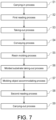
- a method for producing a resin molded product mainly includes: a carrying-in process S1, a first reading process S2, a taking-out process S3, a conveying process S4, a resin molding process S5, a molded substrate taking-out process S6, a molding object accommodating process S7, a second reading process S8, and a carrying-out process S9.
- FIG. 7 describes the processes in order one at a time. However, in reality, the operations in different processes may be executed at the same time, or a specific process may be repeated multiple times.
- the carrying-in process S1 is a process in which the carrier 3 is carried from the outside into the resin molding apparatus 1.
- the carrier 3 accommodating the substrate 2 is carried into the carrier carry-in part 11 of the supply module A (see FIG. 8 ).
- the first reading process S2 is a process in which the code 3c of the carrier 3 and the code 2a of the substrate 2 accommodated in the carrier 3 are read.
- the first camera 14 captures an image of the carrier 3 and the substrate 2 carried into the carrier carry-in part 11.
- the control part 15 reads the code 3c of the carrier 3 and the code 2a of the substrate 2 from the image captured by the first camera 14, and identifies the carrier 3 and the substrate 2.
- the control part 15 stores a correspondence between the carrier 3 and the substrate 2 accommodated in the carrier 3 in association with each other. That is, the control part 15 stores which substrate 2 is accommodated in the carrier 3.
- the taking-out process S3 is a process in which the substrate 2 is taken out from the carrier 3.
- the take-out mechanism 30 takes out the substrate 2 from the carrier 3 of the carrier carry-in part 11 and arranges the substrates 2 side by side on the substrate alignment stage 12 (see FIG. 8 ).
- the substrate alignment stage 12 since six substrates 2 can be arranged on the substrate alignment stage 12, a total of six substrates 2 are taken out from two carriers 3 to the substrate alignment stage 12.
- the main body 41 of the loader 40 is formed so as to project forward.
- the take-out mechanism 30 and the loader 40 may interfere with each other, making it unlikely to arrange the substrate 2 at a position (back part) on the substrate alignment stage 12 close to the loader 40.
- FIG. 4 illustrates that in the present embodiment, as illustrated in FIG.
- the take-out mechanism 30 does not interfere with the loader 40. In this state, the take-out mechanism 30 takes out the substrate 2 to the substrate alignment stage 12.
- the take-out mechanism 30 arranges the substrates 2 in an order from a side (back side) close to the loader 40.
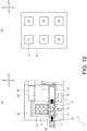
- an arrangement order of (1) to (6) is set in order from the back side of the substrate alignment stage 12. That is, the three substrates 2 taken out from the first carrier 3 are arranged at positions (1) to (3). Accordingly, the substrate 2 can be arranged at the positions (1) and (2) where there is a risk of interference between the take-out mechanism 30 and the loader 40.
- the loader 40 When the loader 40 is retreated to the position shifted to the right from the substrate alignment stage 12, the loader 40 receives the resin tablet T from the resin supply device (not illustrated). In this way, by utilizing the time of retreating as the time for receiving the resin tablet T, production efficiency can be improved.
- the loader 40 and the carrier conveyance unit 50 integrally move leftward. Accordingly, the loader 40 moves to a position (behind the substrate alignment stage 12) where the loader 40 is able to receive the substrate 2 of the substrate alignment stage 12, and the carrier conveyance unit 50 moves to a position (behind the carrier stage 13) where the carrier conveyance unit 50 is able to receive the carrier 3 of the carrier stage 13.
- the first carrier 3 from which the substrates 2 have been taken out is moved from the carrier carry-in part 11 to the carrier stage 13 by an appropriate movement mechanism.
- the carrying-in process S1, the first reading process S2, and the taking-out process S3 are executed again. Accordingly, the substrates 2 accommodated in the second carrier 3 are taken out to the substrate alignment stage 12, and six substrates 2 are aligned on the substrate alignment stage 12.
- the backmost row (positions (1) and (2) in (b) of FIG. 10 ) on the substrate alignment stage 12 overlaps the main body 41 of the loader 40, and in this row, the substrates 2 taken out from the first carrier 3 have already been arranged. That is, since the substrates 2 taken out from the second carrier 3 are not arranged in the backmost row on the substrate alignment stage 12, there is no risk of interference between the take-out mechanism 30 and the loader 40.
- the conveying process S4 is a process in which the substrate 2 is conveyed to the molding die 16 and the carrier 3 is conveyed to the carrier accommodation part 80.
- the conveying process S4 is an embodiment of a molding object conveying process and a conveyance member conveying process according to the present invention.
- the loader 40 holds the six substrates 2 aligned on the substrate alignment stage 12 (see FIG. 4 ).
- the carrier transfer part 60 the carrier 3 of the carrier stage 13 is transferred to carrier placement part 53 of the carrier conveyance unit 50 (see FIG. 5 ). At this time, two carriers 3 are placed on two carrier placement parts 53, respectively.
- the loader 40 and the carrier conveyance unit 50 integrally move rightward.
- the loader 40 delivers the substrate 2 and the resin tablet T to the molding die 16.
- the loader 40 and the carrier conveyance unit 50 further move rightward.
- the carrier accommodation part 80 receives the carrier 3 from the carrier conveyance unit 50.
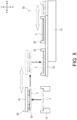
- the lifting part 84 moves to the inside the main body 81 and then moves upward. Accordingly, the support 84b provided at the bottom lifts up the carrier 3 of the carrier placement part 53 from below. By the carrier 3 lifted up, the rotary support 82 is pushed up from below, and the rotary support 82 is rotated upward.
- the carrier 3 that has already been accommodated in the carrier accommodation part 80 is also lifted up to one stage (rotary support 82 directly above) directly above by another support 84b of the lifting part 84. That is, the carrier 3 conveyed to the carry-out module C is accommodated in the bottom stage of the carrier accommodation part 80, and moves up one stage each time another carrier 3 is conveyed.
- a plurality of carriers 3 conveyed to the carry-out module C are arranged side by side and accommodated in order from an upper stage of the carrier accommodation part 80 based on the order in which the carriers 3 were conveyed.
- the substrate 2 (carrier 3) can be smoothly carried into the resin molding apparatus 1.
- the occurrence of waiting time can be prevented and the efficiency of production of resin molded products can be improved. Since the carriers 3 are arranged side by side and accommodated from the top in the order in which they were conveyed, an operator is able to easily and intuitively grasp the order of conveyance of the carriers 3 and efficiently perform confirmation or the like on the carrier 3.
- the above-mentioned processes from the carrying-in process S 1 to the conveying process S4 are repeated according to the number of resin molding modules B.
- the processes are repeated until the substrate 2 is conveyed to the molding die 16 of the two resin molding modules B.
- the resin molding process S5 is a process in which the substrate 2 conveyed to the molding die 16 is resin molded.
- the mold clamping mechanism 17 lifts the lower die and clamps the molding die 16.
- the resin tablet T is heated and melted by the heating part (not illustrated) of the molding die 16, and molten resin generated is used to seal the substrate 2 with resin.
- the molded substrate taking-out process S6 is a process in which the substrate 2 resin molded by the molding die 16 is taken out of the molding die 16.
- the unloader 70 holds the substrate 2 that has been resin molded by the molding die 16, moves the substrate 2 along the rail X to the carry-out module C, and arranges the molded substrate 2 on the molded substrate alignment stage 18 (see FIG. 9 ).
- the unloader 70 carries out the molded substrates 2 in order from the molding die 16 to which the substrate 2 was previously conveyed in the conveying process S4. Accordingly, a correspondence between the substrate 2 and the carrier 3 in the molding object accommodating process S7 described later can be maintained.
- the molding object accommodating process S7 is a process in which the molded substrate 2 is accommodated in the carrier 3.
- the carrier 3 accommodated in the carrier accommodation part 80 is taken out to the carrier carry-out part 19 by an appropriate movement mechanism.
- the carriers 3 accommodated in the top stage are taken out.
- the molding object accommodation mechanism 90 the substrate 2 placed on the molded substrate alignment stage 18 is accommodated in the carrier 3 arranged in the carrier carry-out part 19.
- the second reading process S8 is a process in which the code 3c of the carrier 3 and the code 2a of the molded substrate 2 accommodated in the carrier 3 are read.
- the second camera 20 captures an image of the carrier 3 accommodating the molded substrate 2.
- the control part 15 reads the code 3c of the carrier 3 and the code 2a of the molded substrate 2 from the image captured by the second camera 20, and identifies the carrier 3 and the substrate 2.
- the control part 15 determines whether a correspondence between the carrier 3 and the molded substrate 2 coincides with the correspondence stored in the first reading process S2. If the correspondence between the carrier 3 and the substrate 2 does not coincide with the correspondence stored in the first reading process S2, the control part 15 may, for example, issue a warning to the operator or stop the operation of the resin molding apparatus 1.
- the carrying-out process S9 is a process in which the carrier 3 is carried out from the resin molding apparatus 1 to the outside.
- the carrier 3 accommodating the molded substrate 2 is carried out from the carrier carry-out part 19 of the carry-out module C to the outside (see FIG. 9 ).
- the substrate 2 accommodated in the carrier 3 can be taken out from the carrier 3 and subjected to resin molding. Accordingly, an increase in size of the molding die 16 can be prevented. Since the substrate 2 can be directly positioned with respect to the molding die 16, the positional accuracy of the substrate 2 can be improved.
- the substrate 2 after resin molding can be accommodated in the carrier 3 again.
- the substrate 2 is accommodated in the same carrier 3 that accommodated the substrate 2 before resin molding. Accordingly, for example, management (such as lot management) of the substrate 2 can be performed using the carrier 3.
- the configuration (such as shape or number) of each member described in each of the above embodiments is not particularly limited and can be arbitrarily changed.
- a method for holding the substrate 2 by the loader 40 or the unloader 70 is not particularly limited.
- a method for holding the carrier 3 by the carrier conveyance unit 50 is not particularly limited.
- the number of substrates 2 and carriers 3 conveyed by each device at one time, the arrangement or the like of the substrates 2 on the substrate alignment stage 12 and in the molding die 16 can be arbitrarily changed.
- a code such as a two-dimensional code is assigned to each of the substrate 2 and the carrier 3.
- the present invention is not limited thereto. It is possible to use various other identifiers. For example, it is possible to use a character string or a color as an identifier, or to use, as an identifier, an IC tag that can withstand an environment (such as heat or load) in the resin molding apparatus 1. In the case of using an IC tag, identifier information can be read using, instead of the first camera 14 or the like, a communication device capable of communicating with the IC tag.
- the reading process (first reading process S2 and second reading process S8) illustrated in the present embodiment is an example.
- the code 2a of the substrate 2 and the code 3c of the carrier 3 can be read in any place and at any timing.
- the code 3c of the carrier 3 taken out from the carrier accommodation part 80 is read by the second camera 20 (see the second reading process S8).
- the code 2a of the molded substrate 2 (substrate 2 placed on molded substrate alignment stage 18) before the molded substrate 2 is accommodated in the carrier 3. It is also possible to read, using the first camera 14, the code 2a of the substrate 2 arranged on the substrate alignment stage 12 or the code 3c of the carrier 3 arranged on the carrier stage 13.
- the carrier accommodation part 80 (see FIG. 6 ) illustrated in the present embodiment is an example, and the specific configuration of the carrier accommodation part 80 can be arbitrarily changed.
- the carrier accommodation part 80 can be lifted and lowered in the up-down direction as appropriate according to a height of the carrier 3 being conveyed, and the carrier 3 can be accommodated in each support 80a from the side.
- an example is illustrated in which three substrates 2 are accommodated in one carrier 3 and six substrates 2 (substrates 2 carried in by two carriers 3) are molded by one molding die 16.
- the number of substrates 2 that can be accommodated in the carrier 3 and the number of substrates 2 that can be molded at the same time by one molding die 16 can be arbitrarily changed.
- one carrier 3 is able to accommodate three substrates 2, it is possible that the number of substrates 2 that can be molded by one molding die 16 is eight, ten, twelve and so on.
- the resin molding apparatus 1 Even if the relationship between the number of substrates 2 that can be accommodated in the carrier 3 and the number of substrates 2 that can be molded by the molding die 16 is changed in this way, by the resin molding apparatus 1 according to the present embodiment, the correspondence between the substrate 2 and the carrier 3 before and after molding can be maintained. That is, in the resin molding apparatus 1, since the carrier 3 from which the substrate 2 has been taken out is accommodated in order in the carrier accommodation part 80, and the molded substrate 2 is accommodated in order in the carrier 3, the correspondence between the substrate 2 and the carrier 3 is maintained. Furthermore, in the resin molding apparatus 1, since the correspondence between the substrate 2 and the carrier 3 can be confirmed by the first camera 14 and the second camera 20, the correspondence between the substrate 2 and the carrier 3 can be relatively reliably maintained.
- the operation of the resin molding apparatus 1 illustrated in the present embodiment is an example, and the present invention is not limited thereto. That is, the order or manner of operation of each part of the resin molding apparatus 1 can be arbitrarily changed.
- the resin molding apparatus 1 of a first aspect of the present disclosure includes: the take-out mechanism 30, taking out the substrate 2 (molding object) from the carrier 3 (conveyance member) accommodating the substrate 2; the loader 40 (first molding object conveyance mechanism), conveying the substrate 2 taken out from the carrier 3 to the molding die 16; the carrier accommodation part 80 (conveyance member accommodation part), capable of accommodating the carrier 3 from which the substrate 2 has been taken out; the carrier conveyance unit 50 (conveyance member conveyance mechanism), conveying, to the carrier accommodation part 80, the carrier 3 from which the substrate 2 has been taken out; the mold clamping mechanism 17, clamping the molding die 16 to which the substrate 2 is conveyed, so as to perform resin molding; the unloader 70 (second molding object conveyance mechanism), carrying the substrate 2 after molding out of the molding die 16; and a molding object accommodation mechanism, causing the carrier 3 accommodated in the carrier accommodation part 80 to accommodate the substrate 2 carried out of the molding die 16.
- the substrate 2 accommodated in the carrier 3 can be taken out and subjected to resin molding, and then the substrate 2 can be accommodated in the carrier 3 again. Accordingly, an increase in size of the molding die 16 can be prevented. Since the substrate 2 can be positioned directly with respect to the molding die 16, the positional accuracy of the substrate 2 can be improved.
- the loader 40 and the carrier conveyance unit 50 are movable together in at least a portion of a movement area.
- the loader 40 and the carrier conveyance unit 50 share the movement area, an increase in size of the resin molding apparatus 1 can be prevented.
- the resin molding apparatus 1 of a third aspect according to the first or second aspect includes: a reading part (first camera 14, second camera 20), capable of reading an identifier (code 3c, code 2a) assigned to at least one of the carrier 3 and the substrate 2.
- At least one of the carrier 3 and the substrate 2 can be identified and managed. Accordingly, it is easy to confirm whether the substrate 2 or the carrier 3 is conveyed or molded or the like without any problems.
- the resin molding apparatus 1 of a fourth aspect according to the first or second aspect includes: the first camera 14 (first reading part), capable of reading an identifier assigned to the substrate 2 before molding and the carrier 3 in which the substrate 2 before molding is accommodated; and the second camera 20 (second reading part), capable of reading an identifier assigned to the substrate 2 after molding and the carrier 3 in which the substrate 2 after molding is accommodated.
- the resin molding apparatus 1 of the fourth aspect of the present disclosure a correspondence between the substrate 2 before or after molding and the carrier 3 can be confirmed. Accordingly, since it is easy to maintain the correspondence between the substrate 2 before or after molding and the carrier 3, management (such as lot management) of the substrate 2 using the carrier 3, for example, is facilitated.
- the carrier accommodation part 80 is able to accommodate a plurality of the carriers 3 based on the order in which the carriers 3 are conveyed by the carrier conveyance unit 50. According to the resin molding apparatus 1 of the fifth aspect of the present disclosure, since the carriers 3 can be accommodated in the order in which they were conveyed, it is easy to manage or grasp the order of the carriers 3.
- the resin molding apparatus 1 of a sixth aspect includes: the substrate alignment stage 12 (placement part), on which the substrate 2 taken out by the take-out mechanism 30 is placed.
- the take-out mechanism 30 places the substrate 2 taken out from the carrier 3 on the substrate alignment stage 12 so as not to interfere with the loader 40.
- the take-out mechanism 30 places the substrate 2 at a predetermined position on the substrate alignment stage 12 while the loader 40 is retreated to a retreat position.
- a method for producing a resin molded product according to an eighth aspect of the present disclosure is a method for producing a resin molded product using the resin molding apparatus according to any one of the first to seventh aspects.
- the method includes: the taking-out process S3 in which the substrate 2 is taken out from the carrier 3; the conveying process S4 (molding object conveying process) in which the substrate 2 taken out by the taking-out process S3 is conveyed to the molding die 16; the conveying process S4 (conveyance member conveying process) in which the carrier 3 from which the substrate 2 has been taken out is conveyed; the resin molding process S5 in which the substrate 2 conveyed to the molding die 16 by the conveying process S4 is resin molded; and the molding object accommodating process S7 in which the substrate 2 resin molded by the resin molding process S5 is accommodated in the carrier 3 conveyed by the conveying process S4.
- the substrate 2 accommodated in the carrier 3 can be taken out and subjected to resin molding. Accordingly, an increase in size of the molding die 16 can be prevented. Since the substrate 2 can be positioned directly with respect to the molding die 16, the positional accuracy of the substrate 2 can be improved.
Landscapes
- Engineering & Computer Science (AREA)
- Manufacturing & Machinery (AREA)
- Mechanical Engineering (AREA)
- Robotics (AREA)
- Encapsulation Of And Coatings For Semiconductor Or Solid State Devices (AREA)
- Moulds For Moulding Plastics Or The Like (AREA)
- Injection Moulding Of Plastics Or The Like (AREA)
Abstract
Description
- The present invention relates to technologies of a resin molding apparatus and a method for producing a resin molded product.
- Generally, a technology is known in which a plurality of molding objects such as circuit boards are accommodated in a conveyance member and conveyed together.
Patent Document 1 discloses a technology in which a plurality of circuit boards are subjected to a molding process while being accommodated in a conveyance member called a boat. - Patent Document 1:
Korean Patent Laid-open No. 10-2016-0081289 - In the technology described in
Patent Document 1, in the molding process, the conveyance member accommodating the plurality of molding objects is fed to a molding die for resin molding. Accordingly, since it is necessary for the molding die to accommodate the conveyance member, there is a risk that the molding die may be increased in size. In the technology described inPatent Document 1, positioning of the molding object with respect to the molding die is indirectly performed by positioning the conveyance member with respect to the molding die. Hence, there is a risk that positional accuracy of the molding object with respect to the molding die may be reduced. Accordingly, there is a demand for a technology in which a molding object accommodated in a conveyance member can be taken out for resin molding, followed by being accommodated again in the conveyance member. - The present invention has been made in view of the above circumstances, and a problem to be solved by the present invention is to provide a resin molding apparatus and a method for producing a resin molded product, in which a molding object accommodated in a conveyance member can be taken out for resin molding, followed by being accommodated again in the conveyance member.
- The problem to be solved by the present invention is as described above. In order to solve this problem, a resin molding apparatus according to the present invention includes: a take-out mechanism, taking out a molding object from a conveyance member accommodating the molding object; a first molding object conveyance mechanism, conveying the molding object taken out from the conveyance member to a molding die; a conveyance member accommodation part, capable of accommodating the conveyance member from which the molding object has been taken out; a conveyance member conveyance mechanism, conveying, to the conveyance member accommodation part, the conveyance member from which the molding object has been taken out; a mold clamping mechanism, clamping the molding die to which the molding object is conveyed, so as to perform resin molding; a second molding object conveyance mechanism, carrying the molding object after molding out of the molding die; and a molding object accommodation mechanism, causing the conveyance member accommodated in the conveyance member accommodation part to accommodate the molding object carried out of the molding die.
- A method for producing a resin molded product according to the present invention is a method for producing a resin molded product using the aforementioned resin molding apparatus. The method includes: taking out the molding object from the conveyance member; conveying the molding object taken out in the taking out the molding object to the molding die; conveying the conveyance member from which the molding object has been taken out; resin molding the molding object conveyed to the molding die in the conveying the molding object; and accommodating the molding object resin molded in the resin molding the molding object in the conveyance member conveyed in the conveying the conveyance member.
- According to the present invention, the molding object accommodated in the conveyance member can be taken out for resin molding, followed by being accommodated again in the conveyance member.
-
-
FIG. 1 is a plan view illustrating an overall configuration of a resin molding apparatus according to an embodiment. - (a) of
FIG. 2 is a perspective view illustrating a carrier and a substrate. (b) ofFIG. 2 is a plan view illustrating the carrier and the substrate. - (a) of
FIG. 3 is a partial cross-sectional front view illustrating a manner in which the substrate is suctioned and held by a take-out mechanism. (b) ofFIG. 3 is a partial cross-sectional front view illustrating a manner in which the substrate is held by a clamper of the take-out mechanism. (c) ofFIG. 3 is a front view illustrating a manner in which the substrate is placed on a substrate alignment stage. -
FIG. 4 is a side view illustrating the substrate alignment stage and a loader. -
FIG. 5 is a side view illustrating a carrier conveyance unit and a carrier transfer part. - (a) of
FIG. 6 is a side view illustrating a carrier accommodation part. (b) ofFIG. 6 is a side view illustrating a manner in which the carrier is lifted up. (c) ofFIG. 6 is a side view illustrating a manner in which the carrier is placed on a rotary support. -
FIG. 7 is a flowchart illustrating a method for producing a resin molded product. -
FIG. 8 is a plan view illustrating a manner of conveyance of the substrate and the carrier until resin molding is performed. -
FIG. 9 is a plan view illustrating a manner of conveyance of the substrate and the carrier after resin molding. - (a) of
FIG. 10 is a plan view illustrating a manner in which the loader is retreated to a retreat position. (b) ofFIG. 10 is a plan view illustrating an arrangement order of substrates on the substrate alignment stage. -
FIG. 11 is a side view illustrating a modification of the carrier accommodation part. - In the following, the directions indicated by arrow U, arrow D, arrow L, arrow R, arrow F, and arrow B illustrated in the drawings are defined as an upward direction, a downward direction, a leftward direction, a rightward direction, a forward direction, and a backward direction, respectively, for description.
- First, a configuration of a
resin molding apparatus 1 according to the present embodiment is described with reference toFIG. 1 . Theresin molding apparatus 1 seals an electronic element (hereinafter "chip") such as a semiconductor chip with resin, and produces a resin molded product. Particularly, the present embodiment illustrates theresin molding apparatus 1 that performs resin molding by using a transfer mold method. - The
resin molding apparatus 1 includes a supply module A, a resin molding module B and a carry-out module C as components. Each component is attachable/detachable and interchangeable with respect to any other component. - The supply module A supplies, to the resin molding module B, a
substrate 2 on which a chip is fixed and a resin tablet T of a columnar shape. Thesubstrate 2 is an embodiment of a molding object according to the present invention. As thesubstrate 2, various substrates (such as lead frame, glass epoxy substrate, ceramic substrate, resin substrate, and metal substrate) can be used. The supply module A mainly includes: a carrier carry-inpart 11, asubstrate alignment stage 12, a take-out mechanism 30, acarrier stage 13, aloader 40, acarrier conveyance unit 50, acarrier transfer part 60, afirst camera 14, and acontrol part 15. - The carrier carry-in
part 11 is a portion where acarrier 3 carried into the supply module A from the outside is arranged. The carrier carry-inpart 11 is able to receive thecarrier 3 accommodating thesubstrate 2 and have thecarrier 3 placed on its upper surface. - Here, the
substrate 2 and thecarrier 3 capable of accommodating thesubstrate 2 are described with reference toFIG. 2 . Thecarrier 3 is a member capable of accommodating thesubstrate 2. Thecarrier 3 is an embodiment of a conveyance member according to the present invention. Thecarrier 3 is formed in a substantially rectangular plate shape. Thecarrier 3 is provided with a throughhole 3a, apin 3b, and acode 3c. - The through
hole 3a is formed so as to penetrate thecarrier 3. The throughhole 3a is formed so that three throughholes 3a are arranged side by side in a longitudinal direction of thecarrier 3. Thepin 3b positions thesubstrate 2 accommodated in thecarrier 3. Thepin 3b is formed so as to protrude upward from a surface (upper surface) of thecarrier 3. A plurality ofpins 3b are provided so as to surround a periphery of the throughhole 3a. By accommodating thesubstrate 2 inside thepin 3b, thesubstrate 2 can be arranged at a position facing the throughhole 3a. Thecarrier 3 of the present embodiment is able to accommodate threesubstrates 2. - The
code 3c is provided on the upper surface of thecarrier 3. Thecode 3c is an identifier representing information that makes it possible to identify thecarrier 3. As thecode 3c, for example, a barcode or a two-dimensional code, can be used. - A
code 2a is provided on an upper surface of thesubstrate 2. Thecode 2a is an identifier representing information that makes it possible to identify thesubstrate 2. As thecode 2a, like thecode 3c of thecarrier 3, a two-dimensional code or the like can be used. - The
substrate alignment stage 12 illustrated inFIG. 1 is a portion where thesubstrate 2 taken out from thecarrier 3 is arranged. Thesubstrate alignment stage 12 is an embodiment of a placement part according to the present invention. Thesubstrate alignment stage 12 allows a plurality ofsubstrates 2 to be placed side by side on its upper surface. In the present embodiment, a total of sixsubstrates 2 in three rows in the front-back direction and two rows in the left-right direction (see (b) ofFIG. 10 ) are aligned and placed on thesubstrate alignment stage 12. The arrangement of thesubstrate 2 on thesubstrate alignment stage 12 corresponds to an arrangement of thesubstrate 2 in amolding die 16 described later. That is, the molding die 16 according to the present embodiment is able to perform resin molding on sixsubstrates 2 at one time. Thesubstrate alignment stage 12 is arranged to the back of the carrier carry-inpart 11. - The take-out
mechanism 30 takes out thesubstrate 2 from thecarrier 3 of the carrier carry-inpart 11 and arranges thesubstrate 2 on thesubstrate alignment stage 12. As illustrated inFIG. 3 , the take-outmechanism 30 mainly includes asuction holding part 31, aclamper 32 and apressing part 33. - The
suction holding part 31 suctions and holds thesubstrate 2 placed in the carrier carry-inpart 11. Thesuction holding part 31 is able to suction thesubstrate 2 from below via the throughhole 3a of thecarrier 3. Thesuction holding part 31 can be moved up and down by a lifting mechanism (not illustrated). Accordingly, thesuction holding part 31 is able to lift the suctionedsubstrate 2 upward from thecarrier 3. - The
clamper 32 holds and conveys thesubstrate 2. Theclamper 32 includes a pair of left and right members and a pair of front and back members having an L shape in a side view. Theclamper 32 is able to hold thesubstrate 2 by clamping thesubstrate 2 from four directions, namely left and right, front and back. Theclamper 32 can be moved by a movement mechanism (not illustrated). - The
pressing part 33 presses from above thesubstrate 2 held by theclamper 32. Thepressing part 33 is arranged inside theclamper 32. Thepressing part 33 is placed on thesubstrate 2, thereby being able to press thesubstrate 2 by its own weight. - In the case of taking out the
substrate 2 from thecarrier 3 of the carrier carry-inpart 11 by the take-outmechanism 30, first, as illustrated in (a) ofFIG. 3 , thesubstrate 2 is held by thesuction holding part 31. Next, as illustrated in (b) ofFIG. 3 , thesuction holding part 31 holding thesubstrate 2 as a target rises, and thesubstrate 2 is lifted up. Next, the suctioning by thesuction holding part 31 is canceled, and thesubstrate 2 is held by theclamper 32. Furthermore, thesubstrate 2 is pressed from above by thepressing part 33. Accordingly, thesubstrate 2 can be stably held by theclamper 32. - Next, as illustrated in (c) of
FIG. 3 , theclamper 32 moves to thesubstrate alignment stage 12, and cancels holding of thesubstrate 2 in a predetermined place. Accordingly, thesubstrate 2 can be placed on thesubstrate alignment stage 12. By repeating such an operation of theclamper 32, thesubstrates 2 can be taken out from thecarrier 3 of the carrier carry-inpart 11 and arranged side by side on thesubstrate alignment stage 12. - The
carrier stage 13 illustrated inFIG. 1 is a portion where thecarrier 3 from which thesubstrate 2 has been taken out is arranged in the carrier carry-inpart 11. Thecarrier stage 13 allows thecarrier 3 transferred from the carrier carry-inpart 11 to be placed on its upper surface. - The
loader 40 conveys thesubstrate 2 aligned on thesubstrate alignment stage 12 to the resin molding module B. Theloader 40 receives from a resin supply device (not illustrated) the resin tablet T, holds it, and conveys it together with thesubstrate 2 to the resin molding module B. Here, theloader 40 may receive either thesubstrate 2 or the resin tablet T first, or may receive thesubstrate 2 and the resin tablet T at the same time. That is, a timing at which theloader 40 receives thesubstrate 2 and the resin tablet T is not particularly limited. Theloader 40 is an embodiment of a first molding object conveyance mechanism according to the present invention. Theloader 40 is arranged in a back part of theresin molding apparatus 1. Theloader 40 is movable left and right along a rail X extending across both the left and right ends of theresin molding apparatus 1. As illustrated inFIG. 4 , theloader 40 mainly includes amain body 41, ahead 42 and aclamper 43. - The
main body 41 is a portion that constitutes a main structure of theloader 40. Themain body 41 is configured to be movable left and right along the rail X (seeFIG. 1 ). In order to stably support thehead 42 described later, themain body 41 of the present embodiment is formed so that its front upper portion projects forward. The portion of themain body 41 that projects forward overlaps a back part of thesubstrate alignment stage 12 in the front-back direction. - The
head 42 is a portion where theclamper 43 described later is provided. Thehead 42 is supported so as to be movable in the front-back direction with respect to themain body 41. - The
clamper 43 holds and conveys thesubstrate 2. Theclampers 43 are provided in a number corresponding to the number of the plurality ofsubstrates 2 aligned on thesubstrate alignment stage 12. In the present embodiment, sixclampers 43 are provided on thehead 42 so as to correspond to the sixsubstrates 2. - In the case of conveying the
substrate 2 of thesubstrate alignment stage 12 to the resin molding module B by theloader 40, first, theloader 40 moves along the rail X (seeFIG. 1 ), and stops behind thesubstrate alignment stage 12. Next, as illustrated inFIG. 4 , thehead 42 moves forward with respect to themain body 41 so that thesubstrate 2 on thesubstrate alignment stage 12 and theclamper 43 face each other in the up-down direction. Next, eachclamper 43 holds thesubstrate 2 corresponding thereto, and thehead 42 moves backward with respect to themain body 41. - By moving rightward along the rail X (see
FIG. 1 ) while holding thesubstrate 2, theloader 40 is able to convey thesubstrate 2 to the resin molding module B. By canceling holding of thesubstrate 2 on the molding die 16 of the resin molding module B, theloader 40 is able to carry thesubstrate 2 into the molding die 16. - Although a detailed description is omitted in the present embodiment, the
loader 40 carries the resin tablet T to be used for resin molding into the molding die 16 at the same time as carrying in thesubstrate 2. - The
carrier conveyance unit 50 illustrated inFIG. 1 conveys thecarrier 3 arranged on thecarrier stage 13 to the carry-out module C. Thecarrier conveyance unit 50 is an embodiment of a conveyance member conveyance mechanism according to the present invention. Thecarrier conveyance unit 50 is arranged in the back part of theresin molding apparatus 1. Thecarrier conveyance unit 50 is movable left and right along the rail X. In the present embodiment, thecarrier conveyance unit 50 is configured to move left and right integrally with theloader 40. That is, at least in a movement area along the rail X, theloader 40 and thecarrier conveyance unit 50 are movable together. Accordingly, a movement mechanism (not illustrated) for moving theloader 40 and thecarrier conveyance unit 50 left and right can be used in common. As illustrated inFIG. 5 , thecarrier conveyance unit 50 mainly includes amain body 51, amovable stage 52, and acarrier placement part 53. - The
main body 51 is a portion that constitutes a main structure of thecarrier conveyance unit 50. Themain body 51 is configured to be movable left and right along the rail X (seeFIG. 1 ). - The
movable stage 52 is a portion where thecarrier placement part 53 described later is provided. Themovable stage 52 is provided on an upper part of themain body 51. Themovable stage 52 is supported so as to be movable in the front-back direction with respect to themain body 51. - The
carrier placement part 53 is a portion where thecarrier 3 received from thecarrier stage 13 is placed. Thecarrier placement part 53 is provided on an upper part of themovable stage 52. In the present embodiment, twocarrier placement parts 53 are arranged side by side in the front-back direction. - The
carrier transfer part 60 transfers thecarrier 3 from thecarrier stage 13 to thecarrier conveyance unit 50. As illustrated inFIG. 5 , thecarrier transfer part 60 mainly includes ahead 61 and asuction holding part 62. - The
head 61 is a portion where thesuction holding part 62 described later is provided. Thehead 61 is supported so as to be movable by a movement mechanism (not illustrated). - The
suction holding part 62 suctions and holds thecarrier 3. Thesuction holding part 62 is provided below thehead 61. - In the case of conveying the
carrier 3 of thecarrier stage 13 to the carry-out module C by thecarrier conveyance unit 50, first, thecarrier conveyance unit 50 moves along the rail X (seeFIG. 1 ), and stops behind thecarrier stage 13. Next, as illustrated inFIG. 5 , thecarrier 3 of thecarrier stage 13 is held by thesuction holding part 62 of thecarrier transfer part 60 and is placed on thecarrier placement part 53 of thecarrier conveyance unit 50. At this time, themovable stage 52 moves in the front-back direction as appropriate so that thecarrier placement part 53 moves to a position where thecarrier 3 can be placed. - By moving rightward along the rail X (see
FIG. 1 ) with thecarrier 3 placed on each of the twocarrier placement parts 53, thecarrier conveyance unit 50 is able to convey thecarrier 3 to the carry-out module C. Thecarrier 3 conveyed to the carry-out module C is accommodated in acarrier accommodation part 80 described later. - The
first camera 14 is for reading thecode 2a of thesubstrate 2 and thecode 3c of thecarrier 3. Thefirst camera 14 is an embodiment of a reading part and a first reading part according to the present invention. Thefirst camera 14 is arranged at a position in the supply module A where it is able to capture an image of thecarrier 3 accommodating thesubstrate 2. In the present embodiment, thefirst camera 14 is arranged at a position where it is able to capture an image of thecarrier 3 arranged in the carrier carry-inpart 11. - The
control part 15 controls an operation of each module of theresin molding apparatus 1. By thecontrol part 15, operations of the supply module A, the resin molding module B and the carry-out module C are controlled. The operation of each module can be arbitrarily changed (adjusted) using thecontrol part 15. Thecontrol part 15 is able to manage information on thesubstrate 2 and thecarrier 3 acquired by thefirst camera 14 and asecond camera 20 described later. - In the present embodiment, an example is illustrated in which the
control part 15 is provided in the supply module A. However, it is also possible to provide thecontrol part 15 in any other module. It is also possible to provide a plurality ofcontrol parts 15. For example, it is also possible to provide thecontrol part 15 for each module or each device and individually control the operation of each module or the like while causing each module or the like to operate with each other. - The resin molding module B seals with resin a chip fixed to the
substrate 2. In the present embodiment, two resin molding modules B are arranged side by side. By sealing thesubstrate 2 with resin by the two resin molding modules B in parallel, efficiency of production of resin molded products can be improved. The resin molding module B mainly includes the molding die 16 and amold clamping mechanism 17. - The molding die 16 seals a chip fixed to the
substrate 2 with resin by using a molten resin material. The molding die 16 includes a pair of upper and lower dies, namely a lower die and an upper die. The molding die 16 is provided with a heating part (not illustrated) such as a heater. - The
mold clamping mechanism 17 moves the lower die of the molding die 16 up and down, thereby clamping or opening the molding die 16. - The carry-out module C receives and carries out the
substrate 2 sealed with resin from the resin molding module B. The carry-out module C mainly includes anunloader 70, a moldedsubstrate alignment stage 18, thecarrier accommodation part 80, a carrier carry-outpart 19, a moldingobject accommodation mechanism 90, and thesecond camera 20. - The
unloader 70 holds thesubstrate 2 sealed with resin in the resin molding module B, and conveys thesubstrate 2 to the moldedsubstrate alignment stage 18 of the carry-out module C. Theunloader 70 is an embodiment of a second molding object conveyance mechanism according to the present invention. Theunloader 70 is arranged in the back part of theresin molding apparatus 1. Theunloader 70 is movable left and right along the rail X. - The molded
substrate alignment stage 18 is a portion where the moldedsubstrate 2 conveyed from the resin molding module B is arranged. The moldedsubstrate alignment stage 18 allows a plurality ofsubstrates 2 to be placed side by side on its upper surface. - In the case of conveying, by the
unloader 70, thesubstrate 2 that has been sealed with resin to the carry-out module C, first, theunloader 70 moves along the rail X to the resin molding module B, and suctions and holds thesubstrate 2 that has been resin molded by the molding die 16. Next, theunloader 70 moves along the rail X to the carry-out module C, and arranges the moldedsubstrate 2 on the moldedsubstrate alignment stage 18. - The
carrier accommodation part 80 accommodates thecarrier 3 from which thesubstrate 2 has been taken out in the supply module A. Thecarrier accommodation part 80 is an embodiment of a conveyance member accommodation part according to the present invention. As illustrated inFIG. 6 , thecarrier accommodation part 80 mainly includes amain body 81, arotary support 82, arotary connection part 83, and a liftingpart 84. - The
main body 81 is a portion that constitutes a main structure of thecarrier accommodation part 80. Themain body 81 includes a plurality ofcolumns 81a arranged so as to face each other in the front-back direction. Although not illustrated inFIG. 6 , a plurality ofcolumns 81a are arranged side by side in a depth direction of the paper. Themain body 81 connects upper parts of thecolumns 81a to each other, thereby being formed into a frame shape with an open bottom. - The
rotary support 82 is a portion that supports thecarrier 3. Therotary support 82 is provided so as to protrude inward of themain body 81 from thecolumns 81a in the front-back direction. Therotary support 82 is connected to thecolumn 81a via therotary connection part 83 described later. A plurality of rotary supports 82 are provided so as to be arranged side by side at equal intervals in the up-down direction. The rotary supports 82 provided on thecolumns 81a in the front-back direction are arranged at positions (at the same height) corresponding to each other. - The
rotary connection part 83 is a portion that connects therotary support 82 so that therotary support 82 is rotatable up and down with respect to thecolumn 81a. Therotary connection part 83 supports therotary support 82 so that therotary support 82 is freely rotatable from a state of facing in a substantially horizontal direction to a state of facing in a substantially vertical direction. Accordingly, while receiving no external force, therotary support 82 is rotated downward by its own weight, and faces in the substantially horizontal direction. When an upward external force is applied to therotary support 82, therotary support 82 can be rotated upward. - The lifting
part 84 is for placing thecarrier 3 on therotary support 82. The liftingpart 84 includescolumns 84a arranged to face each other in the front-back direction, and asupport 84b provided to protrude inward from thecolumns 84a in the front-back direction. A plurality ofsupports 84b are provided so as to be arranged side by side at equal intervals in the up-down direction. The interval in the up-down direction between thesupports 84b is formed to be the same as the interval in the up-down direction between the rotary supports 82 provided on themain body 81. - By a driving mechanism (not illustrated), the lifting
part 84 is movable in the front-back and up-down directions with respect to themain body 81. Specifically, as illustrated in (a) ofFIG. 6 , in the liftingpart 84, a series of operations as follows can be repeated: thesupport 84b moves horizontally to a position where it protrudes inward of themain body 81, moves upward in that state, moves horizontally outward of themain body 81, and lowers. The liftingpart 84 and themain body 81 are arranged so as not to interfere with each other. - By a driving mechanism (not illustrated), the
carrier accommodation part 80 as a whole is movable in the front-back and up-down directions. Accordingly, thecarrier accommodation part 80 is able to move to a position where it easily accommodates thecarrier 3. Specifically, as illustrated inFIG. 6 , thecarrier accommodation part 80 is able to move to a position facing from above thecarrier placement part 53 on which thecarrier 3 is placed. - The carrier carry-out
part 19 illustrated inFIG. 1 is a portion where thecarrier 3 to be carried out from the carry-out module C to the outside is arranged. The carrier carry-outpart 19 allows thecarrier 3 received from thecarrier accommodation part 80 to be placed on its upper surface. By the moldingobject accommodation mechanism 90 described later, thecarrier 3 placed on the carrier carry-outpart 19 accommodates thesubstrate 2 that has been molded. Thecarrier 3 accommodating the moldedsubstrate 2 is carried out from the carrier carry-outpart 19 to the outside. - In the molding
object accommodation mechanism 90, thesubstrate 2 placed on the moldedsubstrate alignment stage 18 is accommodated in thecarrier 3 arranged in the carrier carry-outpart 19. As the moldingobject accommodation mechanism 90, for example, like the take-out mechanism 30 (seeFIG. 3 ), a mechanism capable of holding and conveying thesubstrate 2 can be used. A detailed description of the configuration of the moldingobject accommodation mechanism 90 will be omitted. - The
second camera 20 is for reading thecode 2a of the moldedsubstrate 2 and thecode 3c of thecarrier 3. Thesecond camera 20 is an embodiment of a reading part and a second reading part according to the present invention. Thesecond camera 20 is arranged at a position in the carry-out module C where it is able to capture an image of the moldedsubstrate 2 and thecarrier 3 in which the moldedsubstrate 2 is accommodated. In the present embodiment, thesecond camera 20 is arranged at a position where it is able to capture an image of thecarrier 3 arranged in the carrier carry-outpart 19. - In the following, an overview of an operation (method for producing a resin molded product using the resin molding apparatus 1) of the
resin molding apparatus 1 configured as above will be described with reference toFIG. 7 to FIG. 9 . The black arrows illustrated inFIG. 8 andFIG. 9 indicate a manner in which thecarrier 3 moves. The white arrows indicate a manner in which thesubstrate 2 moves. - As illustrated in
FIG. 7 , a method for producing a resin molded product according to the present embodiment mainly includes: a carrying-in process S1, a first reading process S2, a taking-out process S3, a conveying process S4, a resin molding process S5, a molded substrate taking-out process S6, a molding object accommodating process S7, a second reading process S8, and a carrying-out process S9. For ease of description,FIG. 7 describes the processes in order one at a time. However, in reality, the operations in different processes may be executed at the same time, or a specific process may be repeated multiple times. - First, the carrying-in process S1 is executed. The carrying-in process S1 is a process in which the
carrier 3 is carried from the outside into theresin molding apparatus 1. In the carrying-in process S1, thecarrier 3 accommodating thesubstrate 2 is carried into the carrier carry-inpart 11 of the supply module A (seeFIG. 8 ). - Next, the first reading process S2 is executed. The first reading process S2 is a process in which the
code 3c of thecarrier 3 and thecode 2a of thesubstrate 2 accommodated in thecarrier 3 are read. In the first reading process S2, thefirst camera 14 captures an image of thecarrier 3 and thesubstrate 2 carried into the carrier carry-inpart 11. Thecontrol part 15 reads thecode 3c of thecarrier 3 and thecode 2a of thesubstrate 2 from the image captured by thefirst camera 14, and identifies thecarrier 3 and thesubstrate 2. Thecontrol part 15 stores a correspondence between thecarrier 3 and thesubstrate 2 accommodated in thecarrier 3 in association with each other. That is, thecontrol part 15 stores whichsubstrate 2 is accommodated in thecarrier 3. - Next, the taking-out process S3 is executed. The taking-out process S3 is a process in which the
substrate 2 is taken out from thecarrier 3. In the taking-out process S3, the take-outmechanism 30 takes out thesubstrate 2 from thecarrier 3 of the carrier carry-inpart 11 and arranges thesubstrates 2 side by side on the substrate alignment stage 12 (seeFIG. 8 ). In the present embodiment, since sixsubstrates 2 can be arranged on thesubstrate alignment stage 12, a total of sixsubstrates 2 are taken out from twocarriers 3 to thesubstrate alignment stage 12. - Here, an order of arrangement of the
substrate 2 on thesubstrate alignment stage 12 in the taking-out process S3 is described. As illustrated inFIG. 4 , themain body 41 of theloader 40 is formed so as to project forward. Hence, in a state in which theloader 40 is located behind thesubstrate alignment stage 12, the take-outmechanism 30 and theloader 40 may interfere with each other, making it unlikely to arrange thesubstrate 2 at a position (back part) on thesubstrate alignment stage 12 close to theloader 40. For example, in the present embodiment, as illustrated inFIG. 4 , since thesubstrate 2 in the backmost row of the three rows in the front-back direction is arranged at a position overlapping themain body 41 of theloader 40, when thesubstrate 2 is arranged in the backmost row (positions (1) and (2) in (b) ofFIG. 10 ), there is a risk of interference between the take-outmechanism 30 and theloader 40. - In the present embodiment, an example is described in which the positions where the
main body 41 of theloader 40 and thesubstrate 2 are arranged overlap. However, even if the positions where theloader 40 and thesubstrate 2 are arranged do not overlap, it is assumed that the take-outmechanism 30 and theloader 40 may interfere with each other. - Accordingly, in the taking-out process S3, when the
substrate 2 is taken out from thefirst carrier 3, as illustrated in (a) ofFIG. 10 , theloader 40 is retreated to a retreat position shifted from behind to the right of thesubstrate alignment stage 12. In this state, the take-outmechanism 30 does not interfere with theloader 40. In this state, the take-outmechanism 30 takes out thesubstrate 2 to thesubstrate alignment stage 12. - At this time, the take-out
mechanism 30 arranges thesubstrates 2 in an order from a side (back side) close to theloader 40. For example, in the present embodiment, as illustrated in (b) ofFIG. 10 , an arrangement order of (1) to (6) is set in order from the back side of thesubstrate alignment stage 12. That is, the threesubstrates 2 taken out from thefirst carrier 3 are arranged at positions (1) to (3). Accordingly, thesubstrate 2 can be arranged at the positions (1) and (2) where there is a risk of interference between the take-outmechanism 30 and theloader 40. - When the
loader 40 is retreated to the position shifted to the right from thesubstrate alignment stage 12, theloader 40 receives the resin tablet T from the resin supply device (not illustrated). In this way, by utilizing the time of retreating as the time for receiving the resin tablet T, production efficiency can be improved. - When the three
substrates 2 from thefirst carrier 3 are taken out to thesubstrate alignment stage 12, theloader 40 and thecarrier conveyance unit 50 integrally move leftward. Accordingly, theloader 40 moves to a position (behind the substrate alignment stage 12) where theloader 40 is able to receive thesubstrate 2 of thesubstrate alignment stage 12, and thecarrier conveyance unit 50 moves to a position (behind the carrier stage 13) where thecarrier conveyance unit 50 is able to receive thecarrier 3 of thecarrier stage 13. - The
first carrier 3 from which thesubstrates 2 have been taken out is moved from the carrier carry-inpart 11 to thecarrier stage 13 by an appropriate movement mechanism. - After the
first carrier 3 moves from the carrier carry-inpart 11 to thecarrier stage 13, the carrying-in process S1, the first reading process S2, and the taking-out process S3 are executed again. Accordingly, thesubstrates 2 accommodated in thesecond carrier 3 are taken out to thesubstrate alignment stage 12, and sixsubstrates 2 are aligned on thesubstrate alignment stage 12. - At this time, since the
loader 40 is located behind thesubstrate alignment stage 12, the backmost row (positions (1) and (2) in (b) ofFIG. 10 ) on thesubstrate alignment stage 12 overlaps themain body 41 of theloader 40, and in this row, thesubstrates 2 taken out from thefirst carrier 3 have already been arranged. That is, since thesubstrates 2 taken out from thesecond carrier 3 are not arranged in the backmost row on thesubstrate alignment stage 12, there is no risk of interference between the take-outmechanism 30 and theloader 40. - Next, the conveying process S4 is executed. The conveying process S4 is a process in which the
substrate 2 is conveyed to the molding die 16 and thecarrier 3 is conveyed to thecarrier accommodation part 80. The conveying process S4 is an embodiment of a molding object conveying process and a conveyance member conveying process according to the present invention. In the conveying process S4, theloader 40 holds the sixsubstrates 2 aligned on the substrate alignment stage 12 (seeFIG. 4 ). By thecarrier transfer part 60, thecarrier 3 of thecarrier stage 13 is transferred tocarrier placement part 53 of the carrier conveyance unit 50 (seeFIG. 5 ). At this time, twocarriers 3 are placed on twocarrier placement parts 53, respectively. - Next, as illustrated in
FIG. 8 , theloader 40 and thecarrier conveyance unit 50 integrally move rightward. In the resin molding module B, theloader 40 delivers thesubstrate 2 and the resin tablet T to the molding die 16. After that, theloader 40 and thecarrier conveyance unit 50 further move rightward. In the carry-out module C, thecarrier accommodation part 80 receives thecarrier 3 from thecarrier conveyance unit 50. - Here, a manner in which the
carrier accommodation part 80 receives thecarrier 3 in the conveying process S4 is described with reference toFIG. 6 . In the case where thecarrier accommodation part 80 receives thecarrier 3, first, as illustrated in (a) ofFIG. 6 , thecarrier accommodation part 80 moves to above thecarrier placement part 53. - Next, as illustrated in (b) of
FIG. 6 , the liftingpart 84 moves to the inside themain body 81 and then moves upward. Accordingly, thesupport 84b provided at the bottom lifts up thecarrier 3 of thecarrier placement part 53 from below. By thecarrier 3 lifted up, therotary support 82 is pushed up from below, and therotary support 82 is rotated upward. - When the
carrier 3 is lifted up above therotary support 82, therotary support 82 returns to a substantially horizontal position due to its own weight, as illustrated in (c) ofFIG. 6 . In this state, thecarrier 3 is placed on therotary support 82, and the liftingpart 84 is retreated to the outside of themain body 81. In this way, thecarrier 3 of thecarrier placement part 53 is supported by therotary support 82 provided at the bottom of thecarrier accommodation part 80. - At this time, the
carrier 3 that has already been accommodated in thecarrier accommodation part 80 is also lifted up to one stage (rotary support 82 directly above) directly above by anothersupport 84b of the liftingpart 84. That is, thecarrier 3 conveyed to the carry-out module C is accommodated in the bottom stage of thecarrier accommodation part 80, and moves up one stage each time anothercarrier 3 is conveyed. - In this way, a plurality of
carriers 3 conveyed to the carry-out module C are arranged side by side and accommodated in order from an upper stage of thecarrier accommodation part 80 based on the order in which thecarriers 3 were conveyed. In this way, by providing theresin molding apparatus 1 with thecarrier accommodation part 80 and securing an accommodation place for a plurality ofcarriers 3, the substrate 2 (carrier 3) can be smoothly carried into theresin molding apparatus 1. Thus, the occurrence of waiting time can be prevented and the efficiency of production of resin molded products can be improved. Since thecarriers 3 are arranged side by side and accommodated from the top in the order in which they were conveyed, an operator is able to easily and intuitively grasp the order of conveyance of thecarriers 3 and efficiently perform confirmation or the like on thecarrier 3. - The above-mentioned processes from the carrying-in
process S 1 to the conveying process S4 are repeated according to the number of resin molding modules B. For example, in the present embodiment, since two resin molding modules B are provided, the processes are repeated until thesubstrate 2 is conveyed to the molding die 16 of the two resin molding modules B. - Next, the resin molding process S5 is executed. The resin molding process S5 is a process in which the
substrate 2 conveyed to the molding die 16 is resin molded. In the resin molding process S5, themold clamping mechanism 17 lifts the lower die and clamps the molding die 16. The resin tablet T is heated and melted by the heating part (not illustrated) of the molding die 16, and molten resin generated is used to seal thesubstrate 2 with resin. - Next, the molded substrate taking-out process S6 is executed. The molded substrate taking-out process S6 is a process in which the
substrate 2 resin molded by the molding die 16 is taken out of the molding die 16. In the molded substrate taking-out process S6, theunloader 70 holds thesubstrate 2 that has been resin molded by the molding die 16, moves thesubstrate 2 along the rail X to the carry-out module C, and arranges the moldedsubstrate 2 on the molded substrate alignment stage 18 (seeFIG. 9 ). - If a plurality of resin molding modules B (molding dies 16) are provided as in the present embodiment, the
unloader 70 carries out the moldedsubstrates 2 in order from the molding die 16 to which thesubstrate 2 was previously conveyed in the conveying process S4. Accordingly, a correspondence between thesubstrate 2 and thecarrier 3 in the molding object accommodating process S7 described later can be maintained. - Next, the molding object accommodating process S7 is executed. The molding object accommodating process S7 is a process in which the molded
substrate 2 is accommodated in thecarrier 3. In the molding object accommodating process S7, first, thecarrier 3 accommodated in thecarrier accommodation part 80 is taken out to the carrier carry-outpart 19 by an appropriate movement mechanism. At this time, among thecarriers 3 accommodated in thecarrier accommodation part 80, thecarriers 3 accommodated in the top stage are taken out. Next, by the moldingobject accommodation mechanism 90, thesubstrate 2 placed on the moldedsubstrate alignment stage 18 is accommodated in thecarrier 3 arranged in the carrier carry-outpart 19. - Next, the second reading process S8 is executed. The second reading process S8 is a process in which the
code 3c of thecarrier 3 and thecode 2a of the moldedsubstrate 2 accommodated in thecarrier 3 are read. In the second reading process S8, thesecond camera 20 captures an image of thecarrier 3 accommodating the moldedsubstrate 2. Thecontrol part 15 reads thecode 3c of thecarrier 3 and thecode 2a of the moldedsubstrate 2 from the image captured by thesecond camera 20, and identifies thecarrier 3 and thesubstrate 2. Thecontrol part 15 determines whether a correspondence between thecarrier 3 and the moldedsubstrate 2 coincides with the correspondence stored in the first reading process S2. If the correspondence between thecarrier 3 and thesubstrate 2 does not coincide with the correspondence stored in the first reading process S2, thecontrol part 15 may, for example, issue a warning to the operator or stop the operation of theresin molding apparatus 1. - Next, the carrying-out process S9 is executed. The carrying-out process S9 is a process in which the
carrier 3 is carried out from theresin molding apparatus 1 to the outside. In the carrying-out process S9, thecarrier 3 accommodating the moldedsubstrate 2 is carried out from the carrier carry-outpart 19 of the carry-out module C to the outside (seeFIG. 9 ). - As described above, in the
resin molding apparatus 1 according to the present embodiment, thesubstrate 2 accommodated in thecarrier 3 can be taken out from thecarrier 3 and subjected to resin molding. Accordingly, an increase in size of the molding die 16 can be prevented. Since thesubstrate 2 can be directly positioned with respect to the molding die 16, the positional accuracy of thesubstrate 2 can be improved. - In the
resin molding apparatus 1 according to the present embodiment, thesubstrate 2 after resin molding can be accommodated in thecarrier 3 again. At this time, thesubstrate 2 is accommodated in thesame carrier 3 that accommodated thesubstrate 2 before resin molding. Accordingly, for example, management (such as lot management) of thesubstrate 2 can be performed using thecarrier 3. - The above has described an embodiment of the present invention. However, the present invention is not limited to the above embodiment, and appropriate changes can be made within the scope of the technical idea of the invention described in the claims.
- For example, the configuration (such as shape or number) of each member described in each of the above embodiments is not particularly limited and can be arbitrarily changed. As an example, a method for holding the
substrate 2 by theloader 40 or theunloader 70 is not particularly limited. A method for holding thecarrier 3 by thecarrier conveyance unit 50 is not particularly limited. The number ofsubstrates 2 andcarriers 3 conveyed by each device at one time, the arrangement or the like of thesubstrates 2 on thesubstrate alignment stage 12 and in the molding die 16 can be arbitrarily changed. - In the present embodiment, an example is illustrated in which a code such as a two-dimensional code is assigned to each of the
substrate 2 and thecarrier 3. However, the present invention is not limited thereto. It is possible to use various other identifiers. For example, it is possible to use a character string or a color as an identifier, or to use, as an identifier, an IC tag that can withstand an environment (such as heat or load) in theresin molding apparatus 1. In the case of using an IC tag, identifier information can be read using, instead of thefirst camera 14 or the like, a communication device capable of communicating with the IC tag. - The reading process (first reading process S2 and second reading process S8) illustrated in the present embodiment is an example. The
code 2a of thesubstrate 2 and thecode 3c of thecarrier 3 can be read in any place and at any timing. As an example, in the present embodiment, it is illustrated that thecode 3c of thecarrier 3 taken out from thecarrier accommodation part 80 is read by the second camera 20 (see the second reading process S8). However, it is also possible to read thecode 3c of thecarrier 3 accommodated in thecarrier accommodation part 80 in the conveying process S4. Accordingly, thecarrier 3 accommodated in thecarrier accommodation part 80 can be identified, and whether thecarrier 3 is accommodated in a suitable position or the like can be grasped. - In addition, it is also possible to read, using the
second camera 20, thecode 2a of the molded substrate 2 (substrate 2 placed on molded substrate alignment stage 18) before the moldedsubstrate 2 is accommodated in thecarrier 3. It is also possible to read, using thefirst camera 14, thecode 2a of thesubstrate 2 arranged on thesubstrate alignment stage 12 or thecode 3c of thecarrier 3 arranged on thecarrier stage 13. - The carrier accommodation part 80 (see
FIG. 6 ) illustrated in the present embodiment is an example, and the specific configuration of thecarrier accommodation part 80 can be arbitrarily changed. For example, like a modification of thecarrier accommodation part 80 as illustrated inFIG. 11 , it is also possible to accommodate thecarrier 3 in a non-rotatablemultistage support 80a instead of therotary support 82 that is rotatable. In this case, for example, thecarrier accommodation part 80 can be lifted and lowered in the up-down direction as appropriate according to a height of thecarrier 3 being conveyed, and thecarrier 3 can be accommodated in eachsupport 80a from the side. In this case as well, it is desirable that thecarriers 3 be accommodated in order from an upper stage (or lower stage) of thecarrier accommodation part 80 based on the order in which thecarriers 3 were conveyed. - In the present embodiment, an example is illustrated in which three
substrates 2 are accommodated in onecarrier 3 and six substrates 2 (substrates 2 carried in by two carriers 3) are molded by one molding die 16. However, this is an example. The number ofsubstrates 2 that can be accommodated in thecarrier 3 and the number ofsubstrates 2 that can be molded at the same time by one molding die 16 can be arbitrarily changed. For example, while onecarrier 3 is able to accommodate threesubstrates 2, it is possible that the number ofsubstrates 2 that can be molded by one molding die 16 is eight, ten, twelve and so on. Even if the relationship between the number ofsubstrates 2 that can be accommodated in thecarrier 3 and the number ofsubstrates 2 that can be molded by the molding die 16 is changed in this way, by theresin molding apparatus 1 according to the present embodiment, the correspondence between thesubstrate 2 and thecarrier 3 before and after molding can be maintained. That is, in theresin molding apparatus 1, since thecarrier 3 from which thesubstrate 2 has been taken out is accommodated in order in thecarrier accommodation part 80, and the moldedsubstrate 2 is accommodated in order in thecarrier 3, the correspondence between thesubstrate 2 and thecarrier 3 is maintained. Furthermore, in theresin molding apparatus 1, since the correspondence between thesubstrate 2 and thecarrier 3 can be confirmed by thefirst camera 14 and thesecond camera 20, the correspondence between thesubstrate 2 and thecarrier 3 can be relatively reliably maintained. - The operation of the
resin molding apparatus 1 illustrated in the present embodiment is an example, and the present invention is not limited thereto. That is, the order or manner of operation of each part of theresin molding apparatus 1 can be arbitrarily changed. - The
resin molding apparatus 1 of a first aspect of the present disclosure includes: the take-outmechanism 30, taking out the substrate 2 (molding object) from the carrier 3 (conveyance member) accommodating thesubstrate 2; the loader 40 (first molding object conveyance mechanism), conveying thesubstrate 2 taken out from thecarrier 3 to the molding die 16; the carrier accommodation part 80 (conveyance member accommodation part), capable of accommodating thecarrier 3 from which thesubstrate 2 has been taken out; the carrier conveyance unit 50 (conveyance member conveyance mechanism), conveying, to thecarrier accommodation part 80, thecarrier 3 from which thesubstrate 2 has been taken out; themold clamping mechanism 17, clamping the molding die 16 to which thesubstrate 2 is conveyed, so as to perform resin molding; the unloader 70 (second molding object conveyance mechanism), carrying thesubstrate 2 after molding out of the molding die 16; and a molding object accommodation mechanism, causing thecarrier 3 accommodated in thecarrier accommodation part 80 to accommodate thesubstrate 2 carried out of the molding die 16. - According to the
resin molding apparatus 1 of the first aspect of the present disclosure, thesubstrate 2 accommodated in thecarrier 3 can be taken out and subjected to resin molding, and then thesubstrate 2 can be accommodated in thecarrier 3 again. Accordingly, an increase in size of the molding die 16 can be prevented. Since thesubstrate 2 can be positioned directly with respect to the molding die 16, the positional accuracy of thesubstrate 2 can be improved. - In the
resin molding apparatus 1 of a second aspect according to the first aspect, theloader 40 and thecarrier conveyance unit 50 are movable together in at least a portion of a movement area. - According to the
resin molding apparatus 1 of the second aspect of the present disclosure, since theloader 40 and thecarrier conveyance unit 50 share the movement area, an increase in size of theresin molding apparatus 1 can be prevented. - The
resin molding apparatus 1 of a third aspect according to the first or second aspect includes: a reading part (first camera 14, second camera 20), capable of reading an identifier (code 3c,code 2a) assigned to at least one of thecarrier 3 and thesubstrate 2. - According to the
resin molding apparatus 1 of the third aspect of the present disclosure, at least one of thecarrier 3 and thesubstrate 2 can be identified and managed. Accordingly, it is easy to confirm whether thesubstrate 2 or thecarrier 3 is conveyed or molded or the like without any problems. - The
resin molding apparatus 1 of a fourth aspect according to the first or second aspect includes: the first camera 14 (first reading part), capable of reading an identifier assigned to thesubstrate 2 before molding and thecarrier 3 in which thesubstrate 2 before molding is accommodated; and the second camera 20 (second reading part), capable of reading an identifier assigned to thesubstrate 2 after molding and thecarrier 3 in which thesubstrate 2 after molding is accommodated. - According to the
resin molding apparatus 1 of the fourth aspect of the present disclosure, a correspondence between thesubstrate 2 before or after molding and thecarrier 3 can be confirmed. Accordingly, since it is easy to maintain the correspondence between thesubstrate 2 before or after molding and thecarrier 3, management (such as lot management) of thesubstrate 2 using thecarrier 3, for example, is facilitated. - In the
resin molding apparatus 1 of a fifth aspect according to any one of the first to fourth aspects, thecarrier accommodation part 80 is able to accommodate a plurality of thecarriers 3 based on the order in which thecarriers 3 are conveyed by thecarrier conveyance unit 50. According to theresin molding apparatus 1 of the fifth aspect of the present disclosure, since thecarriers 3 can be accommodated in the order in which they were conveyed, it is easy to manage or grasp the order of thecarriers 3. - The
resin molding apparatus 1 of a sixth aspect according to any one of the first to fifth aspects includes: the substrate alignment stage 12 (placement part), on which thesubstrate 2 taken out by the take-outmechanism 30 is placed. The take-outmechanism 30 places thesubstrate 2 taken out from thecarrier 3 on thesubstrate alignment stage 12 so as not to interfere with theloader 40. - According to the
resin molding apparatus 1 of the fifth aspect of the present disclosure, interference with theloader 40 when thesubstrate 2 is taken out can be prevented. - In the
resin molding apparatus 1 of a seventh aspect according to the sixth aspect, the take-outmechanism 30 places thesubstrate 2 at a predetermined position on thesubstrate alignment stage 12 while theloader 40 is retreated to a retreat position. - According to the
resin molding apparatus 1 of the seventh aspect of the present disclosure, interference with theloader 40 when thesubstrate 2 is taken out can be prevented. - A method for producing a resin molded product according to an eighth aspect of the present disclosure is a method for producing a resin molded product using the resin molding apparatus according to any one of the first to seventh aspects. The method includes: the taking-out process S3 in which the
substrate 2 is taken out from thecarrier 3; the conveying process S4 (molding object conveying process) in which thesubstrate 2 taken out by the taking-out process S3 is conveyed to the molding die 16; the conveying process S4 (conveyance member conveying process) in which thecarrier 3 from which thesubstrate 2 has been taken out is conveyed; the resin molding process S5 in which thesubstrate 2 conveyed to the molding die 16 by the conveying process S4 is resin molded; and the molding object accommodating process S7 in which thesubstrate 2 resin molded by the resin molding process S5 is accommodated in thecarrier 3 conveyed by the conveying process S4. - According to the method for producing a resin molded product of the eighth aspect of the present disclosure, the
substrate 2 accommodated in thecarrier 3 can be taken out and subjected to resin molding. Accordingly, an increase in size of the molding die 16 can be prevented. Since thesubstrate 2 can be positioned directly with respect to the molding die 16, the positional accuracy of thesubstrate 2 can be improved. -
- 1: resin molding apparatus
- 2: substrate
- 3: carrier
- 12: substrate alignment stage
- 14: first camera
- 16: molding die
- 17: mold clamping mechanism
- 20: second camera
- 30: take-out mechanism
- 40: loader
- 50: carrier conveyance unit
- 70: unloader
- 80: carrier accommodation part
Claims (8)
- A resin molding apparatus, comprising:a take-out mechanism, taking out a molding object from a conveyance member accommodating the molding object;a first molding object conveyance mechanism, conveying the molding object taken out from the conveyance member to a molding die;a conveyance member accommodation part, capable of accommodating the conveyance member from which the molding object has been taken out;a conveyance member conveyance mechanism, conveying, to the conveyance member accommodation part, the conveyance member from which the molding object has been taken out;a mold clamping mechanism, clamping the molding die to which the molding object is conveyed, so as to perform resin molding;a second molding object conveyance mechanism, carrying the molding object after molding out of the molding die; anda molding object accommodation mechanism, causing the conveyance member accommodated in the conveyance member accommodation part to accommodate the molding object carried out of the molding die.
- The resin molding apparatus according to claim 1, wherein
the first molding object conveyance mechanism and the conveyance member conveyance mechanism are movable together in at least a portion of a movement area. - The resin molding apparatus according to claim 1 or 2, comprising:
a reading part, capable of reading an identifier assigned to at least one of the conveyance member and the molding object. - The resin molding apparatus according to claim 1 or 2, comprising:a first reading part, capable of reading an identifier assigned to the molding object before molding and the conveyance member in which the molding object before molding is accommodated; anda second reading part, capable of reading an identifier assigned to the molding object after molding and the conveyance member in which the molding object after molding is accommodated.
- The resin molding apparatus according to any one of claims 1 to 4, wherein
the conveyance member accommodation part is capable of accommodating a plurality of the conveyance members based on an order in which the conveyance members are conveyed by the conveyance member conveyance mechanism. - The resin molding apparatus according to any one of claims 1 to 5, comprising:a placement part, on which the molding object taken out by the take-out mechanism is placed, whereinthe take-out mechanism places the molding object taken out from the conveyance member on the placement part so as not to interfere with the first molding object conveyance mechanism.
- The resin molding apparatus according to claim 6, wherein
the take-out mechanism places the molding object at a predetermined position on the placement part while the first molding object conveyance mechanism is retreated to a retreat position. - A method for producing a resin molded product using the resin molding apparatus according to any one of claims 1 to 7, the method comprising:taking out the molding object from the conveyance member;conveying the molding object taken out in the taking out the molding object to the molding die;conveying the conveyance member from which the molding object has been taken out;resin molding the molding object conveyed to the molding die in the conveying the molding object; andaccommodating the molding object resin molded in the resin molding the molding object in the conveyance member conveyed in the conveying the conveyance member.
Applications Claiming Priority (2)
| Application Number | Priority Date | Filing Date | Title |
|---|---|---|---|
| JP2022102379A JP7691397B2 (en) | 2022-06-27 | 2022-06-27 | Resin molding device and method for manufacturing resin molded product |
| PCT/JP2023/005313 WO2024004257A1 (en) | 2022-06-27 | 2023-02-15 | Resin molding apparatus and method for producing resin molded article |
Publications (2)
| Publication Number | Publication Date |
|---|---|
| EP4545269A1 true EP4545269A1 (en) | 2025-04-30 |
| EP4545269A4 EP4545269A4 (en) | 2025-10-01 |
Family
ID=89381860
Family Applications (1)
| Application Number | Title | Priority Date | Filing Date |
|---|---|---|---|
| EP23830713.6A Pending EP4545269A4 (en) | 2022-06-27 | 2023-02-15 | Resin molding apparatus and method for producing a resin molded article |
Country Status (6)
| Country | Link |
|---|---|
| EP (1) | EP4545269A4 (en) |
| JP (1) | JP7691397B2 (en) |
| KR (1) | KR20250007620A (en) |
| CN (1) | CN119317529A (en) |
| TW (1) | TWI839110B (en) |
| WO (1) | WO2024004257A1 (en) |
Families Citing this family (1)
| Publication number | Priority date | Publication date | Assignee | Title |
|---|---|---|---|---|
| JP7645422B1 (en) * | 2024-06-25 | 2025-03-13 | Towa株式会社 | Resin molding device and method for manufacturing resin molded product |
Family Cites Families (12)
| Publication number | Priority date | Publication date | Assignee | Title |
|---|---|---|---|---|
| JPH09306930A (en) * | 1996-05-16 | 1997-11-28 | Oki Electric Ind Co Ltd | Magazine conveying control method |
| KR20050097730A (en) * | 2004-04-02 | 2005-10-10 | 삼성전자주식회사 | Auto molding apparatus for semiconductor chip package |
| KR100776630B1 (en) * | 2006-12-27 | 2007-11-15 | 세크론 주식회사 | Resin compression molding apparatus for semiconductor device and semiconductor device resin molding method using same |
| KR20100013056A (en) * | 2008-07-30 | 2010-02-09 | 세크론 주식회사 | Apparatus for molding an electronic device |
| JP5914136B2 (en) | 2012-04-25 | 2016-05-11 | 富士機械製造株式会社 | Wafer management system, attachment and magazine rack of die supply apparatus |
| JP2015104881A (en) * | 2013-11-29 | 2015-06-08 | 三菱樹脂株式会社 | Thermoformed body and method for producing thermoformed body |
| KR20160081289A (en) | 2014-12-31 | 2016-07-08 | 앰코 테크놀로지 코리아 주식회사 | Boat for semiconductor package fabrication and method for fabricating the semiconductor package |
| JP6744780B2 (en) * | 2016-08-09 | 2020-08-19 | アピックヤマダ株式会社 | Resin molding equipment |
| TWI787411B (en) * | 2018-02-16 | 2022-12-21 | 日商山田尖端科技股份有限公司 | Resin molding device |
| JP6989409B2 (en) | 2018-02-16 | 2022-01-05 | アピックヤマダ株式会社 | Resin molding device and resin molding method |
| JP6721738B2 (en) | 2019-02-14 | 2020-07-15 | アピックヤマダ株式会社 | Resin molding equipment |
| JP7444453B2 (en) * | 2020-11-25 | 2024-03-06 | アピックヤマダ株式会社 | Resin sealing equipment and resin sealing method |
-
2022
- 2022-06-27 JP JP2022102379A patent/JP7691397B2/en active Active
-
2023
- 2023-02-15 EP EP23830713.6A patent/EP4545269A4/en active Pending
- 2023-02-15 CN CN202380044681.9A patent/CN119317529A/en active Pending
- 2023-02-15 WO PCT/JP2023/005313 patent/WO2024004257A1/en not_active Ceased
- 2023-02-15 KR KR1020247039816A patent/KR20250007620A/en active Pending
- 2023-02-15 TW TW112105242A patent/TWI839110B/en active
Also Published As
| Publication number | Publication date |
|---|---|
| TWI839110B (en) | 2024-04-11 |
| EP4545269A4 (en) | 2025-10-01 |
| WO2024004257A1 (en) | 2024-01-04 |
| CN119317529A (en) | 2025-01-14 |
| TW202400395A (en) | 2024-01-01 |
| JP2024003323A (en) | 2024-01-15 |
| KR20250007620A (en) | 2025-01-14 |
| JP7691397B2 (en) | 2025-06-11 |
Similar Documents
| Publication | Publication Date | Title |
|---|---|---|
| TWI787411B (en) | Resin molding device | |
| CN110682271B (en) | Equipment and method for replacing pins of carriers in circular connector production line | |
| CN111299075B (en) | A junction box shaping and assembly equipment | |
| JP2019145548A (en) | Resin mold device and resin mold method | |
| KR20200105720A (en) | Resin molding device | |
| CN215542400U (en) | Loading equipment of PCBA board rubber coating carrier | |
| WO2024004257A1 (en) | Resin molding apparatus and method for producing resin molded article | |
| EP2934078B1 (en) | Die supply apparatus | |
| KR20190043731A (en) | Die bonding apparatus | |
| JP2001244279A (en) | Substrate supply method, substrate supply device, chip supply device, and chip mounting device | |
| KR20020089358A (en) | Apparatus and method for processing elecronic components | |
| KR102397598B1 (en) | Resin molding product manufacturing method and resin molding apparatus | |
| JP4398768B2 (en) | Semiconductor resin sealing device and resin sealing method | |
| CN102881612B (en) | Frame feeding system and frame feeding method | |
| US20250038017A1 (en) | Resin sealing device | |
| CN113707562A (en) | Resin molding apparatus | |
| CN111232622A (en) | Full-automatic efficient laser system and method in SIP packaging process | |
| JP2011040478A (en) | Electronic component mounting device | |
| JP2009105257A (en) | Resin sealing device | |
| CN115867017A (en) | An automatic placement production line and process technology for slender flexible auxiliary materials | |
| TWI890467B (en) | Resin molding apparatus and resin molded product manufacturing method | |
| CN212023987U (en) | Full-automatic efficient laser system in SIP packaging process | |
| TW202535640A (en) | Resin sealing device and workpiece feeding method | |
| JP3613013B2 (en) | Electronic component mounting apparatus and electronic component mounting method | |
| JP2025161025A (en) | Resin sealing equipment |
Legal Events
| Date | Code | Title | Description |
|---|---|---|---|
| STAA | Information on the status of an ep patent application or granted ep patent |
Free format text: STATUS: THE INTERNATIONAL PUBLICATION HAS BEEN MADE |
|
| PUAI | Public reference made under article 153(3) epc to a published international application that has entered the european phase |
Free format text: ORIGINAL CODE: 0009012 |
|
| STAA | Information on the status of an ep patent application or granted ep patent |
Free format text: STATUS: REQUEST FOR EXAMINATION WAS MADE |
|
| 17P | Request for examination filed |
Effective date: 20241216 |
|
| AK | Designated contracting states |
Kind code of ref document: A1 Designated state(s): AL AT BE BG CH CY CZ DE DK EE ES FI FR GB GR HR HU IE IS IT LI LT LU LV MC ME MK MT NL NO PL PT RO RS SE SI SK SM TR |
|
| REG | Reference to a national code |
Ref country code: DE Ref legal event code: R079 Free format text: PREVIOUS MAIN CLASS: B29C0045020000 Ipc: B29C0045140000 |
|
| A4 | Supplementary search report drawn up and despatched |
Effective date: 20250903 |
|
| DAV | Request for validation of the european patent (deleted) | ||
| DAX | Request for extension of the european patent (deleted) | ||
| RIC1 | Information provided on ipc code assigned before grant |
Ipc: B29C 45/14 20060101AFI20250828BHEP Ipc: B29C 45/02 20060101ALI20250828BHEP Ipc: B29C 45/42 20060101ALI20250828BHEP Ipc: H01L 21/56 20060101ALN20250828BHEP Ipc: H01L 21/683 20060101ALN20250828BHEP Ipc: H01L 21/67 20060101ALN20250828BHEP |