EP4544980A2 - Optisches endoskop - Google Patents
Optisches endoskop Download PDFInfo
- Publication number
- EP4544980A2 EP4544980A2 EP24218130.3A EP24218130A EP4544980A2 EP 4544980 A2 EP4544980 A2 EP 4544980A2 EP 24218130 A EP24218130 A EP 24218130A EP 4544980 A2 EP4544980 A2 EP 4544980A2
- Authority
- EP
- European Patent Office
- Prior art keywords
- optical
- endoscope
- waveguides
- waveguide block
- optical fiber
- Prior art date
- Legal status (The legal status is an assumption and is not a legal conclusion. Google has not performed a legal analysis and makes no representation as to the accuracy of the status listed.)
- Pending
Links
Images


Classifications
-
- G—PHYSICS
- G02—OPTICS
- G02B—OPTICAL ELEMENTS, SYSTEMS OR APPARATUS
- G02B23/00—Telescopes, e.g. binoculars; Periscopes; Instruments for viewing the inside of hollow bodies; Viewfinders; Optical aiming or sighting devices
- G02B23/24—Instruments or systems for viewing the inside of hollow bodies, e.g. fibrescopes
- G02B23/26—Instruments or systems for viewing the inside of hollow bodies, e.g. fibrescopes using light guides
-
- A—HUMAN NECESSITIES
- A61—MEDICAL OR VETERINARY SCIENCE; HYGIENE
- A61B—DIAGNOSIS; SURGERY; IDENTIFICATION
- A61B1/00—Instruments for performing medical examinations of the interior of cavities or tubes of the body by visual or photographical inspection, e.g. endoscopes; Illuminating arrangements therefor
- A61B1/00064—Constructional details of the endoscope body
- A61B1/0011—Manufacturing of endoscope parts
-
- A—HUMAN NECESSITIES
- A61—MEDICAL OR VETERINARY SCIENCE; HYGIENE
- A61B—DIAGNOSIS; SURGERY; IDENTIFICATION
- A61B1/00—Instruments for performing medical examinations of the interior of cavities or tubes of the body by visual or photographical inspection, e.g. endoscopes; Illuminating arrangements therefor
- A61B1/00163—Optical arrangements
- A61B1/00165—Optical arrangements with light-conductive means, e.g. fibre optics
- A61B1/00167—Details of optical fibre bundles, e.g. shape or fibre distribution
-
- A—HUMAN NECESSITIES
- A61—MEDICAL OR VETERINARY SCIENCE; HYGIENE
- A61B—DIAGNOSIS; SURGERY; IDENTIFICATION
- A61B1/00—Instruments for performing medical examinations of the interior of cavities or tubes of the body by visual or photographical inspection, e.g. endoscopes; Illuminating arrangements therefor
- A61B1/00163—Optical arrangements
- A61B1/00165—Optical arrangements with light-conductive means, e.g. fibre optics
- A61B1/0017—Details of single optical fibres, e.g. material or cladding
-
- A—HUMAN NECESSITIES
- A61—MEDICAL OR VETERINARY SCIENCE; HYGIENE
- A61B—DIAGNOSIS; SURGERY; IDENTIFICATION
- A61B1/00—Instruments for performing medical examinations of the interior of cavities or tubes of the body by visual or photographical inspection, e.g. endoscopes; Illuminating arrangements therefor
- A61B1/00163—Optical arrangements
- A61B1/00188—Optical arrangements with focusing or zooming features
-
- A—HUMAN NECESSITIES
- A61—MEDICAL OR VETERINARY SCIENCE; HYGIENE
- A61B—DIAGNOSIS; SURGERY; IDENTIFICATION
- A61B1/00—Instruments for performing medical examinations of the interior of cavities or tubes of the body by visual or photographical inspection, e.g. endoscopes; Illuminating arrangements therefor
- A61B1/00163—Optical arrangements
- A61B1/00195—Optical arrangements with eyepieces
-
- A—HUMAN NECESSITIES
- A61—MEDICAL OR VETERINARY SCIENCE; HYGIENE
- A61B—DIAGNOSIS; SURGERY; IDENTIFICATION
- A61B1/00—Instruments for performing medical examinations of the interior of cavities or tubes of the body by visual or photographical inspection, e.g. endoscopes; Illuminating arrangements therefor
- A61B1/06—Instruments for performing medical examinations of the interior of cavities or tubes of the body by visual or photographical inspection, e.g. endoscopes; Illuminating arrangements therefor with illuminating arrangements
- A61B1/07—Instruments for performing medical examinations of the interior of cavities or tubes of the body by visual or photographical inspection, e.g. endoscopes; Illuminating arrangements therefor with illuminating arrangements using light-conductive means, e.g. optical fibres
-
- G—PHYSICS
- G02—OPTICS
- G02B—OPTICAL ELEMENTS, SYSTEMS OR APPARATUS
- G02B23/00—Telescopes, e.g. binoculars; Periscopes; Instruments for viewing the inside of hollow bodies; Viewfinders; Optical aiming or sighting devices
- G02B23/24—Instruments or systems for viewing the inside of hollow bodies, e.g. fibrescopes
- G02B23/2407—Optical details
- G02B23/2461—Illumination
- G02B23/2469—Illumination using optical fibres
-
- G—PHYSICS
- G02—OPTICS
- G02B—OPTICAL ELEMENTS, SYSTEMS OR APPARATUS
- G02B6/00—Light guides; Structural details of arrangements comprising light guides and other optical elements, e.g. couplings
- G02B6/24—Coupling light guides
- G02B6/26—Optical coupling means
Definitions
- the invention relates to an optical endoscope comprising an optical fiber element with a proximal end and a distal end.
- Optical endoscopes are instruments for looking inside a volume through a small opening. Endoscopes are typically used in medicine to look inside the human body. However, the use of endoscopes is not restricted to medicine. Endoscopes are also used for visual inspection of workpieces such as engines, turbines or the like. Endoscopes for such a technical use are sometimes referred to as "borescope”.
- endoscope as used herein shall refer to both medical and non-medical use.
- An endoscope usually comprises a flexible optics that guides the light between the so-called “distal end” inside the object to be examined to the so called “proximal end” outside of the object.
- a flexible optics that guides the light between the so-called “distal end” inside the object to be examined to the so called “proximal end” outside of the object.
- there is some miniaturized scanning and/or imaging apparatus at the distal end while more elaborate optics, whose purpose includes magnifying the transmitted image onto a digital image sensor or an eyepiece, are found at the proximal end.
- endoscopes obtain a scattering image, however fluorescence imaging and optical coherence tomography are widely used too.
- optical fibers are used for the flexible optics.
- fiber bundles as well as multi-mode fibers can be used.
- Multi-core fibers have also been commonly used.
- optical fibers An important limitation that is connected with the use of optical fibers is the low numerical aperture of the fibers that results in a small acceptance angle and thus a small field of view.
- One approach known from WO 2017/016663 A1 uses an endoscope with a flexible tubular sheath containing optical fibers. A distal tip with multiple optical ports spread in three-dimensions including flexible waveguides is described. These waveguides either continue into the body of the endoscope through the same number of fibers or are coupled to a multiplexer which connects to a few or a single optical fiber continuing through to the endoscope's proximal end.
- the technology to produce the endoscope with a corresponding distal tip is cumbersome and costly.
- the flexible waveguides connecting the optical ports to the proximal end or to the multiplexer have a high possibility of breakage during fabrication (as they have to be subjected to strong bending) or during use of the latter if a proper package is not employed.
- a multiplexer including a cascade of couplers and splitters, significant signal loss occurs. For many applications, such additional optical loss is detrimental, if not completely preventing the functionality of the device.
- the scheme is also difficult to adapt to different fiber geometries, for example to different multi-core fiber geometries.
- the optical fiber element may be flexible. However, the optical fiber element may also be rigid.
- the optical fiber element may particularly comprise one or more optical fibers, particularly in a common flexible jacket.
- the common flexible jacket may be made of a plastic material, particularly an elastomer.
- the optical waveguide block may be rigidly coupled to the distal end of the optical fiber element.
- the optical waveguide block may be fixed or immovable with respect to the distal end of the optical fiber element.
- the optical waveguide block may be coupled or affixed to the distal end of the optical fiber element either via a mechanical, an adhesive (chemical) and/or a fusion (thermal) fixing.
- the optical waveguide block may be coupled to the distal end of the optical fiber element such that light may be transmitted via the two or more optical waveguides and the optical fiber element to the proximal end of the endoscope. For instance, a butt coupling may be realized.
- the number of optical waveguides in the optical waveguide block is not particularly limited. The actual number depends on the intended application. For many applications, four or more optical waveguides may be used.
- the two or more optical waveguides may be arbitrarily arranged within the optical waveguide block, particularly depending on the desired application.
- the optical waveguides may particularly be arranged in a three-dimensional (3-D), non-intersecting manner.
- the optical waveguides may also extend in two dimensions (2-D).
- One or more of the optical waveguides may be curved.
- One or more of the optical waveguides may be straight or uncurved. If both ends of all the waveguides are arranged in a common plane, the optical waveguides are considered to be arranged in a 2-D distribution, otherwise in a 3-D distribution.
- the two or more optical waveguides may be single-mode or multi-mode waveguides. It is possible to vary from a single-mode to a multi-mode waveguide by increasing the cross section and/or the refractive index contrast of the waveguide.
- the refractive index contrast corresponds to the difference in the refractive index between the waveguide and its surrounding medium (cladding).
- the two or more optical waveguides may be integrally formed with the rigid material of the optical waveguide block.
- the two or more optical waveguides may be formed by the rigid material itself. In this way, no separate elements need to be introduced into the optical wave guide block which yields a simplified structure with high mechanical reliability.
- the two or more optical waveguides may particularly be formed by parts of the rigid material having a higher refractive index than the surrounding parts.
- the optical waveguides thus, may be formed by a positive refractive index change in the rigid material.
- the surrounding parts of the rigid material may form the cladding of the optical waveguides.
- the two or more optical waveguides may particularly be obtained by ultrafast laser inscription through the volume of the optical waveguide block.
- the ultrafast laser inscription is preferably performed with laser pulses of duration lower than 1 ps.
- a filter or other optical element may be formed in the optical waveguide block, particularly obtained by ultrafast laser inscription.
- one or more FBG (Fiber Bragg Grating) filters may be formed in the optical waveguide block, particularly in one or more of the optical waveguides.
- the rigid material is optically transparent at the operating wavelength of the optical endoscope. It may also be optically transparent for the laser used for ultrafast laser inscription.
- the operating wavelength of the optical endoscope may be below 2 ⁇ m, particularly below 1.6 ⁇ m, for instance between 1.3 ⁇ m and 1.55 ⁇ m.
- the optical waveguide block may consist of the rigid material.
- the rigid material may particularly comprise or consist of a glass, a polymer and/or a semiconductor. Examples of materials are silicate and/or multi-component glasses, perfluorinated polymer, silicon and silicon nitride.
- Each of the two or more optical waveguides may comprise one end facing the optical fiber element and arranged in a first surface of the optical waveguide block, the so-called coupling end, and one end facing away from the optical fiber element and arranged in a second surface of the optical waveguide block, the so-called object end.
- the object end may particularly face the object when the endoscope is in use.
- the two or more optical waveguides may particularly form tubes or channels connecting the coupling end and the object end. Geometrically, thus, the two or more optical waveguides resemble optical fibers.
- the cladding may be provided by the rigid material surrounding the optical waveguides, as mentioned above.
- the optical fiber element may comprise a multi-core optical fiber, wherein the two or more optical waveguides are coupled to the optical fiber element such that at the coupling end the two or more optical waveguides line up with the cores of the multi-core optical fiber.
- a butt coupling of the cores of the multi-core fiber with the optical waveguides in the optical waveguide block can be realized.
- the waveguide block can be index matched to the optical fiber element. In this way, it is possible to reduce optical loss.
- the individual cores of the multi-core optical fiber may be single mode cores at the operating wavelength.
- Single mode waveguides are compatible with coherent imaging techniques such as optical coherence tomography.
- the optical fiber element may comprise a multi-mode optical fiber, wherein the two or more optical waveguides are coupled to the multimode optical fiber via a photonic lantern section formed in the rigid material of the optical waveguide block. In this way, it is possible to omit the multiplexing section as used in the prior art.
- a photonic lantern corresponds to an optical element connecting a multi-mode waveguide to multiple waveguides with fewer modes, particularly single mode.
- the geometry of the optical waveguide block is not particularly limited. Also the geometry of the optical waveguides within the rigid material is not particularly limited. Both may depend on the desired application.
- the optical waveguide block may be rotationally symmetric, for instance cylindrical or in the form of a truncated cone.
- the optical waveguide block may also have the form of two or more rotationally symmetric elements joined to each other, for instance, a circular cylinder and a hemisphere.
- the optical waveguide block may comprise or consist of one or more planar chips.
- Each planar chip can comprise one or more of the optical waveguides.
- the waveguides may be curved.
- Each planar chip may also comprise multiplexers and/or splitters formed therein, particularly by ultrafast laser inscription.
- a "planar chip” refers to a geometrical form whose extension in one direction (thickness) is significantly less (at least three times less) than the extension in the other two directions (length, width).
- a planar chip may be a rectangular plate. More than one planar chip may be connected to each other thereby forming a more complex geometry for the optical waveguide block. For instance, two planar chips may be arranged orthogonal to each other, particularly such that each of the planar chips is divided in half by the other of the two planar chips.
- the coupling end may be a polished, flat surface perpendicular to the longitudinal axis of the optical fiber element.
- the object end may be a flat surface perpendicular to or inclined with regard to the longitudinal axis of the optical fiber element. By using an inclined surface, back reflections may be minimized or removed.
- the object end may be polished flat.
- the object end may be curved; particularly the object end may be hemispherical. In this way, it is possible to map a flat 2-D distribution of waveguide ends present at the coupling end to a 3-D hemisphere. In this way, it is possible to expand the solid angle and consequently also the field of view.
- the object end may be curved continuously or discontinuously.
- the object end may also be composed of a plurality of polished flat facets, joined together to form a curved, particularly hemispherical, surface.
- the mapping of the spatial distribution of the ends of the two or more optical waveguides at the coupling end to the spatial distribution of the ends of the two or more optical waveguides at the object end may be mirror symmetrical with regard to a plane extending parallel to the longitudinal axis of the optical fiber element.
- optical waveguides in the optical waveguide block may intersect a plane extending parallel to the longitudinal axis when extending from the coupling end to the object end. In this way, a larger radius of curvature for the optical waveguides can be realized, reducing curvature losses.
- Optical waveguides extending from the two sides of the plane may intersect the plane at different positions, thereby avoiding intersecting waveguides. Also inter-waveguide coupling can be kept acceptably low in this way.
- the plane extending parallel to the longitudinal axis may include a symmetry axis of the optical fiber element and, thus, may correspond to a symmetry plane of the optical fiber element.
- the plane may also form a symmetry plane of the optical waveguide block coupled to the optical fiber element. If the optical waveguide block is rotationally symmetric, the plane may also include the rotational axis of symmetry of the optical waveguide block. As mentioned above, the plane may also form a symmetry plane for the distribution of the optical waveguides in the optical waveguide block. Instead of the symmetry plane, the symmetry axis of the optical fiber element or of the optical waveguide block may be used as reference for some embodiments.
- Additional optics may be coupled with the optical waveguide block.
- the additional optical elements may be used for focusing light, for instance.
- a separate micro lens may be coupled to each end of the optical waveguides at the object end of the optical waveguide block, for instance.
- the one or more micro lenses may be made from fused silica, silicon or any other material transparent at the operating wavelength of the endoscope.
- the one or more micro lenses may particularly be plano-convex lenses.
- Optical waveguides in the optical waveguide block may be arranged such that waveguides having ends at the coupling end with a radial distance less than a predefined distance to the longitudinal axis of the optical fiber element are curved towards a lateral part of the object end, while waveguides having ends at the coupling end with a radial distance to the longitudinal axis of the optical fiber element larger than the predefined distance continue to a forward facing part of the object end.
- This configuration again allows reducing curvature loss since small curvature radii for waveguides close to a side surface of the optical waveguide block are omitted.
- the predefined distance may be larger than one quarter and smaller than three quarters of the radial extension of the optical waveguide block at the coupling end, in particular half of the radial extension of the optical waveguide block at the coupling end.
- the longitudinal axis of the optical fiber element is in this case considered to extend into the optical waveguide block to form a reference axis for the optical waveguide block.
- the longitudinal axis of the optical waveguide block does not necessarily coincide with the longitudinal axis of the optical fiber element. If the optical waveguide block is rotationally symmetric, the rotational axis of symmetry may coincide with the longitudinal axis of the optical fiber element. In other words, the rotational axis of symmetry of the optical waveguide block may line up with the longitudinal axis of the optical fiber element. In this case, the rotational axis of symmetry of the optical waveguide block may be similarly used as reference axis.
- a "lateral part" of the object end refers to a surface area of the optical waveguide block facing in a direction inclined to the reference axis of the optical waveguide block (corresponding, for instance, to the extension of the longitudinal axis of the optical fiber element) at an angle of more than or equal to 45° and less than or equal to 135°.
- a "forward facing part" of the object end refers to a surface area of the optical waveguide block facing in a direction inclined to the reference axis of the optical waveguide block at an angle of less than 45° and a “backward facing part” of the object end refers to a surface area of the optical waveguide block facing in a direction inclined to the reference axis of the optical waveguide block at an angle of more than 135°.
- the reference axis is considered to have a direction facing away from the distal end of the optical fiber element.
- the "forward facing part" of the object end faces away from the distal end of the optical fiber element.
- the respective angles may be measured between the surface normal of the respective surface area and the reference axis.
- the surface normal may be considered to have a direction facing away from the optical waveguide block.
- the optical waveguide block may be covered at least partially by an electrically conductive layer.
- the electrically conductive layer may be electrically coupled to a further conductor extending to the proximal end of the optical endoscope. Via this conductor and the conductive layer of the optical waveguide block, it is possible to transmit current to the distal end for ablation purposes.
- the electrically conductive layer covering the optical waveguide block may particularly be transparent or semi-transparent at the operating wavelength of the optical endoscope.
- the electrically conductive layer may be formed of a transparent or semi-transparent material and/or the electrically conductive layer may have a thickness allowing a predefined fraction of light at the operating wavelength of the optical endoscope to pass through the layer without being scattered.
- the predefined fraction may be 50% or more.
- Possible materials for the electrically conductive layer include wide band gap semiconductor materials, such as indium tin oxide or aluminum doped zinc oxide, ultrathin metals, silver nanowires and/or metal grids.
- ultrathin metals and metal grids may be combined to achieve high optical transmission for wavelengths above 1 ⁇ m while still maintaining low electrical resistance (high conductance).
- the material or at least the outer surface of the electrically conductive layer needs to be compatible with human tissues.
- gold may be used as material for the electrically conductive layer or its outer surface.
- the outer surface refers to the surface of the electrically conductive layer that may come into contact with human tissues when the optical endoscope is in use.
- the electrically conductive layer may comprise openings for light to enter the two or more optical waveguides.
- the openings may form optical ports for the two or more optical waveguides.
- the electrically conductive material covering the optical waveguide block is transparent or semi-transparent at the operating wavelength of the optical endoscope, openings for light to enter the two or more optical waveguides are not necessarily provided. In other words, no such openings or ports may be formed in this case. Thus, the manufacturing may be simplified.
- the invention further provides an optical waveguide block for an optical endoscope, the optical waveguide block comprising a rigid material, wherein two or more optical waveguides are formed in the rigid material.
- the optical waveguide block may comprise any one or more of the above-described features.
- the invention further provides a method for manufacturing an optical endoscope comprising the steps of:
- the two or more optical waveguides may particularly be formed by ultrafast laser inscription.
- the optical endoscope particularly the optical waveguide block, may comprise any one or more of the above-described features.
- an optical waveguide block 6 is arranged at the distal end 4 of the optical fiber element 2.
- the optical waveguide block 6 comprises a rigid material in which two or more optical waveguides are formed. This optical waveguide block 6 allows providing an improved optical endoscope 1 as will also become apparent from the specific embodiments described herein below.
- the optical fiber element 2 extends along a longitudinal direction, which defines the longitudinal axis of the optical endoscope 1. Since the optical fiber element 2 is usually flexible, the longitudinal direction/axis will normally be curved.
- the optical fiber element 2 is usually cylindrical with the central axis defining the symmetry axis of the cylinder.
- the longitudinal axis of the optical fiber element 2 can be considered as extending beyond its proximal and distal ends, in particular as straight lines perpendicular to the proximal/distal end surface.
- the longitudinal axis of the optical fiber element 2 thus is used herein as a reference axis with regard to which indications such as "lateral” or “radial” should be understood, particularly with respect to the optical waveguide block 6.
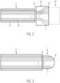
- FIG. 2 illustrates a first embodiment of the invention.
- the optical fiber element 2 comprises a multi-core fiber with a plurality of cores 10 coated in a common, flexible polymer jacket 11. Many different types of multi-core fibers are known.
- the invention is not particularly limited to any specific embodiment for the multi-core fiber nor to any specific arrangement of the fibers in the optical fiber element 2.
- the optical waveguide block 6 has the form of a cuboid in this specific embodiment and is made of glass.
- the optical waveguide block 6 may also be cylindrical or may have any other desired shape.
- a cylindrical optical waveguide block 6 would have the same appearance in the cross-sectional view of Figure 2 as a cuboid one.
- the invention is not limited to glass as a rigid material for the optical waveguide block 6.
- the optical waveguide block 6 could also be formed of a rigid polymer or a rigid semiconductor, which are particularly optically transparent at the operating wavelength of the optical endoscope.
- the optical waveguide block 6 comprises a plurality of 3-D ultrafast laser inscribed optical waveguides 7 leading from a coupling end 8 of the optical waveguide block 6 to an object end 9.
- the coupling end 8 faces the optical fiber element 2 while the object end 9 faces the object when the optical endoscope is in use, for instance, the interior of an organ of the human body.
- Ultrafast laser inscription is known as such and works as follows: a high-intensity, focused femtosecond laser beam is applied to the rigid material in order to induce a permanent positive refractive index change through a multi-photon absorption mechanism.
- the path traced out by the focus therefore becomes a light guiding core due to its resultant higher refractive index, with effective cladding provided by the unmodified remainder of the rigid material block.
- Doing multiple scanning runs enables writing an arbitrary number of waveguides with arbitrary 3-D shapes in a single block of rigid material.
- Various approaches are possible to account for the fact that the shape of the focused laser is not the ideal shape of a waveguide core, for instance, using multiple scanning runs with a slight offset from each other and annealing the rigid material block after ultrafast laser inscription by heating.
- the object end 9 is a polished flat surface, perpendicular to the longitudinal axis of the optical fiber element 2.
- the longitudinal axis of the optical fiber element 2 may be considered as extending into the optical waveguide block 6, with the object end 9 being perpendicular thereto.
- the object end 9 may be arranged at a slight angle with regard to the longitudinal axis to remove or minimize back reflections. The angle depends on the refractive indices of the block and the surrounding medium. Typically it varies between a few degrees and ten degrees. The angle, thus, may be more than 1° and less than 10°.
- the coupling end 8 is defined by the surface of the optical waveguide block 6 where the ends of the optical waveguides 7 are arranged facing the optical fiber element 2
- the object end 9 is defined as the surface area of the optical waveguide block 6 in which the ends of the optical waveguides 7 are arranged facing the object when the optical endoscope is in use or in other words, facing away from the optical fiber element 2.
- the optical waveguides 7 in the optical waveguide block 6 fan out from the coupling end 8 towards the object end 9, effectively replicating the distribution of the waveguide ends at the coupling end 8, just with a larger inter-core spacing.
- the field of view is thus increased.
- the field of view is increased at the expense of spatial resolution; however, the acceptance angle remains the same as in a regular multi-core fiber endoscope.
- Every core 10 of the multi-core fiber of the optical fiber element 2 butt-couples in this example to an end of an optical waveguide 7 at the coupling end 8 (not illustrated in the Figure). In this way, transmission of light from the object end 9 to the proximal end of the optical endoscope is possible.
- At least one additional optical element 12 such as a GRIN rod lens or micro lens or multiple such lenses, may be attached at the object end 9.
- this embodiment is also compatible with coherent imaging techniques such as optical coherence tomography.
- the object end pattern of the optical waveguides 7 is not particularly limited.
- the distribution could also be mono-dimensional, i.e. a linear array of waveguides or otherwise different from the distribution of the ends of the waveguide 7 at the coupling end 8.
- the coupling end pattern may be one-dimensional or two-dimensional.
- optical waveguide block 6 ensures long-term stability and no degradation in optical signal.
- Figure 3 illustrates another embodiment of the invention.
- the optical waveguide block 6 has an object end 9 that is hemispherical.
- Optical waveguides 7 in the optical waveguide block 6, thus, map the flat 2-D distribution of the coupling end 8 to the 3-D hemisphere, thereby increasing the solid angle.
- optical waveguides 7 also lead to a side surface of the optical waveguide block 6 with respect to the longitudinal axis of the optical fiber element 2 as reference axis. In this way, the solid angle may be increased to 2 ⁇ .
- the maximum solid angle can be even larger in the case of the optical waveguides 7 bending backwards. This may introduce, however, optical loss, since waveguide losses increase as the waveguide radius decreases.
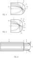
- Figures 4 and 5 illustrate possible alternatives to the optical waveguide block 6 illustrated in Figure 3 .
- a theoretical plane 13 extending parallel to the longitudinal axis of the optical fiber element 2 and including the symmetry axis of the optical fiber element 2 is illustrated.
- the rotational axis of symmetry of the optical waveguide block 6 may be used as reference.
- Waveguides 7 lead from one lateral side of the plane or axis 13 at the coupling end 8 to the other lateral side of the plane or axis 13 on the object end 9. In this way, it is possible to maintain the radius of curvature large enough to keep curvature losses acceptably low.
- the optical waveguides 7 may be designed with angles and distances from each other in such a manner to minimize crosstalk (see Figure 5 ). In both alternatives ( Figure 4 and Figure 5 ) the optical waveguides 7 are not intersecting in three-dimension, but only in projection.
- Figure 5 further shows the alternative of composing the object end 9 of a plurality of flat facets 14, which together join in a prismatic manner to cover the hemispherical object end 9.
- This discontinuous design of the hemispherical object end 9 may be used independently of the optical waveguide pattern inside the optical waveguide block 6.
- Figure 6 illustrates a further embodiment of the invention, which basically corresponds to the embodiment described with reference to Figure 3 .
- micro lenses 15 are affixed to the optical waveguide ends at the object end 9 of the optical waveguide block 6.
- microscopic plano-convex lenses 15 made from fused silica or silicon are used in this example.
- a hemispherical object space is imaged and transmitted through the optical fiber element 2 towards the proximal end.
- optical coherence tomography may be used, as mentioned above, with the number of pixels equal to the number of waveguides in the optical waveguide block 6.
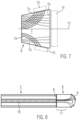
- Figure 7 illustrates an alternative optical waveguide block 6, which may be used to reduce curvature loss.
- optical waveguides 7a closer to the plane or axis 13 are mapped to the lateral surface areas of the object end, while the optical waveguides 7b closer to the edge of the optical waveguide block 6 map to a forward facing surface area of the object end.
- the side facing surface area can either be a cylindrical surface, or through the use of micro lenses with different focal lengths can be modified to more closely match a hemispherical surface.
- the forward facing surface area can be flat as illustrated in Figure 2 or curved as illustrated, for instance, in Figure 3 .
- Optional micro lenses or GRIN optics are illustrated as additional optical elements 15 in Figure 7 .
- FIGs 9a and 9b illustrate so-called "photonic lanterns".
- Photonic lanterns are optical devices connecting a multi-mode waveguide to a plurality of waveguides with fewer, possibly only single, modes.
- Figure 9a shows the alternative of mapping one multi-mode waveguide 19 to a number of single mode waveguides 18.
- Figure 9b illustrates spreading out of a multi-mode waveguide 19 to a plurality of single mode waveguides 18 and then recombining to a single multi-mode waveguide 20 again.
- FBG Fiber Bragg Grating
- FBG Fiber Bragg Grating
- the modes of the multi-mode fiber 16 first couple to the individual waveguides in the photonic lantern section 17 and then spread out according to the needs of the specific embodiment.
- the object end 8 is made consistent with the example shown in Figure 6 .
- Figure 10 shows another embodiment of an optical endoscope according to the invention.
- a single mode or multi-mode fiber 21 may be used.
- a photonic lantern section 17 is written into the optical waveguide block 6.
- the optical lantern section 17 is implemented in a branched manner, that is, with a spread out from a multi-mode waveguide to fewer-moded waveguides occurring over multiple fan out steps.
- each branch functions as a splitter rather than a fan out device.
- the photonic lantern section 17 thus, functions as the multiplexing element.
- optical endoscopes are intended to be used for radiofrequency ablation of internal tissues.
- the embodiment of Figure 11 is suitable for such purposes.
- a conductive tube 22 of a conductive material, such as a metal is provided around optical fiber element 2 with an optional insulating sheath 23.
- the optical waveguide block 6 is embedded in a conductive layer 24, which has proper openings 25 for optical access to the optical waveguides of the optical waveguide block 6.
- Current may be transmitted to the distal end by means of the conductive tube 22 surrounding the optical fiber element 2.
- several layers of conductive and insulating tubes may surround the optical fiber element 2 to enable ring electrodes for monitoring purposes.
- the conductive tube 22 is in electrical contact with the conductive layer 24 of the optical waveguide block 6, so that the current may be transmitted to the conductive layer 24 of the optical waveguide block 6. In this way, ablation treatments can be performed.
- This radiofrequency ablation functionality can be used with any one of the previous embodiments. If a multi-mode fiber should be used for the optical fiber element 2, a photonic lantern section as illustrated in Figures 8 or 10 can be inscribed in the optical waveguide block.
- the conductive layer 24 may be semi-transparent or transparent at the operating wavelength of the optical endoscope.
- the openings 25 may be omitted.
- the conductive layer 24 may particularly be formed of a transparent or semi-transparent material and/or may be made sufficiently thin to allow light at the operating wavelength of the optical endoscope to pass at least partially through the layer.
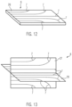
- the optical waveguide block 6 is formed as a planar chip 26 with a 2-D distribution of five exemplary optical waveguides 7 formed therein.
- the central optical waveguide extends straight or uncurved from the coupling end to the object end, while the other optical waveguides are curved towards a side surface of the planar chip 26.
- the thickness of the planar chip 26 is significantly less than its length and width.
- the optical waveguide block 6 is formed by two orthogonally intersecting planar chips 26, 27 each with a 2-D distribution of optical waveguides 7 formed therein.
- the planar chips 26, 27 are arranged such that each of planar chips 26, 27 is divided in half by the respective other chip. In this way, a 3-D distribution of the optical waveguides 7 may be achieved while reducing the amount of rigid material.
- Each of the planar chips 26, 27 may comprise two or more elements.
- the planar chip 26 may comprise two halves, each connected to the planar chip 27.
- the optical waveguide block is often shown as spaced from the distal end of the optical fiber element, This is only for illustrational purposes.
- the optical waveguide block is actually coupled with the distal end of the optical fiber element such that light may be transmitted via the two or more optical waveguides and the optical fiber element to the proximal end of the endoscope. For instance, a butt coupling may be realized.
- the discussed embodiments are not intended as limitations, but serve as examples illustrating features and advantages of the invention.
- the pattern of the optical waveguides in the optical waveguide block is determined by the desired application.
- the optical waveguide block may consist of any transparent, rigid material of appropriate index of refraction that offers the possibility of hosting 3-D optical waveguides as described.
Landscapes
- Physics & Mathematics (AREA)
- Health & Medical Sciences (AREA)
- Life Sciences & Earth Sciences (AREA)
- Surgery (AREA)
- Optics & Photonics (AREA)
- Engineering & Computer Science (AREA)
- Medical Informatics (AREA)
- General Health & Medical Sciences (AREA)
- Pathology (AREA)
- Nuclear Medicine, Radiotherapy & Molecular Imaging (AREA)
- Biomedical Technology (AREA)
- Heart & Thoracic Surgery (AREA)
- Biophysics (AREA)
- Molecular Biology (AREA)
- Animal Behavior & Ethology (AREA)
- Radiology & Medical Imaging (AREA)
- Public Health (AREA)
- Veterinary Medicine (AREA)
- General Physics & Mathematics (AREA)
- Astronomy & Astrophysics (AREA)
- Manufacturing & Machinery (AREA)
- Endoscopes (AREA)
- Instruments For Viewing The Inside Of Hollow Bodies (AREA)
- Optical Couplings Of Light Guides (AREA)
Priority Applications (1)
| Application Number | Priority Date | Filing Date | Title |
|---|---|---|---|
| EP24218130.3A EP4544980A3 (de) | 2017-11-30 | 2017-11-30 | Optisches endoskop |
Applications Claiming Priority (3)
| Application Number | Priority Date | Filing Date | Title |
|---|---|---|---|
| PCT/ES2017/070787 WO2019106209A1 (es) | 2017-11-30 | 2017-11-30 | Endoscopio óptico |
| EP17840589.0A EP3719557B1 (de) | 2017-11-30 | 2017-11-30 | Endoscopio óptico |
| EP24218130.3A EP4544980A3 (de) | 2017-11-30 | 2017-11-30 | Optisches endoskop |
Related Parent Applications (1)
| Application Number | Title | Priority Date | Filing Date |
|---|---|---|---|
| EP17840589.0A Division EP3719557B1 (de) | 2017-11-30 | 2017-11-30 | Endoscopio óptico |
Publications (2)
| Publication Number | Publication Date |
|---|---|
| EP4544980A2 true EP4544980A2 (de) | 2025-04-30 |
| EP4544980A3 EP4544980A3 (de) | 2025-07-30 |
Family
ID=61198865
Family Applications (2)
| Application Number | Title | Priority Date | Filing Date |
|---|---|---|---|
| EP17840589.0A Active EP3719557B1 (de) | 2017-11-30 | 2017-11-30 | Endoscopio óptico |
| EP24218130.3A Pending EP4544980A3 (de) | 2017-11-30 | 2017-11-30 | Optisches endoskop |
Family Applications Before (1)
| Application Number | Title | Priority Date | Filing Date |
|---|---|---|---|
| EP17840589.0A Active EP3719557B1 (de) | 2017-11-30 | 2017-11-30 | Endoscopio óptico |
Country Status (8)
| Country | Link |
|---|---|
| US (1) | US12282151B2 (de) |
| EP (2) | EP3719557B1 (de) |
| JP (1) | JP7289845B2 (de) |
| CN (1) | CN111788509A (de) |
| AU (1) | AU2017441379B2 (de) |
| CA (1) | CA3083870A1 (de) |
| DE (1) | DE17840589T1 (de) |
| WO (1) | WO2019106209A1 (de) |
Families Citing this family (7)
| Publication number | Priority date | Publication date | Assignee | Title |
|---|---|---|---|---|
| CA3125916C (en) * | 2019-01-09 | 2023-09-12 | Vena Medical Holdings Corp. | Cerebrovascular pathology viewing and treatment |
| JP7664931B2 (ja) | 2020-01-13 | 2025-04-18 | メドルミクス,エセ.エレ. | アブレーションカテーテルを使用する病変の光学的な分析および予測のためのシステム |
| CN115003206A (zh) * | 2020-01-13 | 2022-09-02 | 梅德路米克斯有限公司 | 用于将光纤组装在导管尖端中的方法、装置和支撑结构 |
| CN114929098B (zh) | 2020-01-13 | 2024-10-29 | 梅德路米克斯有限公司 | 使用脉冲场或其它能量源的光学引导消融系统、导管和消融方法 |
| US11331142B2 (en) | 2020-01-13 | 2022-05-17 | Medlumics S.L. | Methods, devices, and support structures for assembling optical fibers in catheter tips |
| CA3150572A1 (en) | 2021-03-04 | 2022-09-04 | Medlumics S.L. | Methods, devices, and support structures for assembling optical fibers in catheter tips |
| US20240019550A1 (en) * | 2022-07-13 | 2024-01-18 | Robert Bosch Gmbh | Scanning light source without moving parts |
Citations (1)
| Publication number | Priority date | Publication date | Assignee | Title |
|---|---|---|---|---|
| WO2017016663A1 (en) | 2015-07-29 | 2017-02-02 | Medlumics S.L. | Radiofrequency ablation catheter with optical tissue evaluation |
Family Cites Families (37)
| Publication number | Priority date | Publication date | Assignee | Title |
|---|---|---|---|---|
| US4366565A (en) * | 1980-07-29 | 1982-12-28 | Herskowitz Gerald J | Local area network optical fiber data communication |
| EP0211976B1 (de) * | 1985-08-13 | 1989-11-15 | Sumitomo Electric Industries Limited | Verfahren zur Herstellung eines optischen Sensors |
| JPH0681506U (ja) * | 1993-05-11 | 1994-11-22 | 日本光電工業株式会社 | 撮像装置の対物アダプタ |
| JPH08179131A (ja) * | 1994-12-22 | 1996-07-12 | Yasuo Kitada | 像伝送体、その製造方法及びそれを使用した像伝送装置 |
| US8024027B2 (en) * | 1998-09-03 | 2011-09-20 | Hyperspectral Imaging, Inc. | Infrared endoscopic balloon probes |
| US6845184B1 (en) * | 1998-10-09 | 2005-01-18 | Fujitsu Limited | Multi-layer opto-electronic substrates with electrical and optical interconnections and methods for making |
| DE10008918A1 (de) | 2000-02-25 | 2001-08-30 | Biotronik Mess & Therapieg | Ablationskatheter zur Erzeugung linearer Läsionen in Herzmuskelgewebe |
| US20030208252A1 (en) | 2001-05-14 | 2003-11-06 | O' Boyle Gary S. | Mri ablation catheter |
| JP2003167203A (ja) * | 2001-11-30 | 2003-06-13 | Olympus Optical Co Ltd | 内視鏡装置 |
| US7130498B2 (en) * | 2003-10-16 | 2006-10-31 | 3M Innovative Properties Company | Multi-layer optical circuit and method for making |
| US7349589B2 (en) * | 2004-04-08 | 2008-03-25 | Omniguide, Inc. | Photonic crystal fibers and medical systems including photonic crystal fibers |
| US7773849B2 (en) * | 2004-12-14 | 2010-08-10 | Oms Displays Ltd. | Device and method for optical resizing and backlighting |
| US7391561B2 (en) * | 2005-07-29 | 2008-06-24 | Aculight Corporation | Fiber- or rod-based optical source featuring a large-core, rare-earth-doped photonic-crystal device for generation of high-power pulsed radiation and method |
| US7450241B2 (en) * | 2005-09-30 | 2008-11-11 | Infraredx, Inc. | Detecting vulnerable plaque |
| US20080089641A1 (en) | 2006-10-09 | 2008-04-17 | Feldchtein Felix I | Optoelectronic lateral scanner and optical probe with distal rotating deflector |
| US9622706B2 (en) | 2007-07-12 | 2017-04-18 | Volcano Corporation | Catheter for in vivo imaging |
| US8301027B2 (en) | 2008-05-02 | 2012-10-30 | Massachusetts Institute Of Technology | Agile-beam laser array transmitter |
| ES2517915T3 (es) | 2008-06-02 | 2014-11-04 | Lightlab Imaging, Inc. | Métodos cuantitativos para obtener características de un tejido a partir de imágenes de tomografía por coherencia óptica |
| WO2010011820A2 (en) | 2008-07-23 | 2010-01-28 | St. Jude Medical, Inc. | Ablation and monitoring system including a fiber optic imaging catheter and an optical coherence tomography system |
| CN103118620B (zh) | 2010-05-12 | 2015-09-23 | 施菲姆德控股有限责任公司 | 小轮廓的电极组件 |
| US8548286B2 (en) * | 2011-03-02 | 2013-10-01 | Eastman Kodak Company | Imaging laser diodes with a lightwave circuit |
| US8478086B2 (en) * | 2011-03-02 | 2013-07-02 | Eastman Kodak Company | Imaging laser diodes with a lightwave circuit |
| US11051698B2 (en) | 2011-11-14 | 2021-07-06 | Koninklijke Philips N.V. | Optical microscopy probe for scanning microscopy of an associated object |
| US9062960B2 (en) * | 2012-02-07 | 2015-06-23 | Medlumics S.L. | Flexible waveguides for optical coherence tomography |
| US20140055562A1 (en) * | 2012-08-27 | 2014-02-27 | Joseph R. Demers | Endoscopic synthetic stereo imaging method and apparatus |
| KR102141992B1 (ko) * | 2013-01-15 | 2020-08-06 | 매직 립, 인코포레이티드 | 초고해상도 스캐닝 섬유 디스플레이 |
| US10098694B2 (en) * | 2013-04-08 | 2018-10-16 | Apama Medical, Inc. | Tissue ablation and monitoring thereof |
| US9874749B2 (en) * | 2013-11-27 | 2018-01-23 | Magic Leap, Inc. | Virtual and augmented reality systems and methods |
| EP3011380B1 (de) * | 2013-06-19 | 2020-09-16 | Optiscan Pty Ltd | Optischer scanner und optische sonde mit gescannter linse |
| JP6253527B2 (ja) * | 2014-06-24 | 2017-12-27 | オリンパス株式会社 | 内視鏡装置 |
| US9661986B2 (en) | 2014-07-24 | 2017-05-30 | Z Square Ltd. | Multicore fiber endoscopes |
| US20160357007A1 (en) * | 2015-05-05 | 2016-12-08 | Eric Swanson | Fixed distal optics endoscope employing multicore fiber |
| US10254536B2 (en) * | 2015-07-20 | 2019-04-09 | Magic Leap, Inc. | Collimating fiber scanner design with inward pointing angles in virtual/augmented reality system |
| JP6799835B2 (ja) * | 2015-08-27 | 2020-12-16 | バー‐イラン、ユニバーシティーBar−Ilan University | マルチ光結合チャネルモジュールおよび関連する計算方法 |
| CN108139518B (zh) * | 2015-10-06 | 2024-03-29 | 奇跃公司 | 具有反向角衍射光栅的虚拟/增强现实系统 |
| EP3222964B1 (de) * | 2016-03-25 | 2020-01-15 | Fogale Nanotech | Chromatische konfokale vorrichtung und verfahren zur 2d/3d-inspektion eines objekts wie etwa eines wafers |
| WO2018022319A1 (en) * | 2016-07-29 | 2018-02-01 | Corning Optical Communications LLC | Waveguide connector elements and optical assemblies incorporating the same |
-
2017
- 2017-11-30 DE DE17840589.0T patent/DE17840589T1/de active Pending
- 2017-11-30 EP EP17840589.0A patent/EP3719557B1/de active Active
- 2017-11-30 AU AU2017441379A patent/AU2017441379B2/en active Active
- 2017-11-30 US US16/768,566 patent/US12282151B2/en active Active
- 2017-11-30 WO PCT/ES2017/070787 patent/WO2019106209A1/es not_active Ceased
- 2017-11-30 CN CN201780098202.6A patent/CN111788509A/zh active Pending
- 2017-11-30 CA CA3083870A patent/CA3083870A1/en active Pending
- 2017-11-30 JP JP2020547317A patent/JP7289845B2/ja active Active
- 2017-11-30 EP EP24218130.3A patent/EP4544980A3/de active Pending
Patent Citations (1)
| Publication number | Priority date | Publication date | Assignee | Title |
|---|---|---|---|---|
| WO2017016663A1 (en) | 2015-07-29 | 2017-02-02 | Medlumics S.L. | Radiofrequency ablation catheter with optical tissue evaluation |
Non-Patent Citations (1)
| Title |
|---|
| K.M. DAVISK. MIURAN. SUGIMOTOK. HIRAO: "Writing waveguides in glass with a femtosecond laser", OPTICS LETTERS, vol. 21, no. 21, 1996, pages 1729 |
Also Published As
| Publication number | Publication date |
|---|---|
| US20200310103A1 (en) | 2020-10-01 |
| EP3719557B1 (de) | 2025-01-08 |
| JP7289845B2 (ja) | 2023-06-12 |
| CA3083870A1 (en) | 2019-06-06 |
| WO2019106209A1 (es) | 2019-06-06 |
| AU2017441379B2 (en) | 2024-01-04 |
| US12282151B2 (en) | 2025-04-22 |
| CN111788509A (zh) | 2020-10-16 |
| EP3719557A1 (de) | 2020-10-07 |
| DE17840589T1 (de) | 2021-01-14 |
| AU2017441379A1 (en) | 2020-06-18 |
| EP4544980A3 (de) | 2025-07-30 |
| EP3719557C0 (de) | 2025-01-08 |
| JP2021514797A (ja) | 2021-06-17 |
Similar Documents
| Publication | Publication Date | Title |
|---|---|---|
| EP3719557B1 (de) | Endoscopio óptico | |
| US8145018B2 (en) | Apparatus for obtaining information for a structure using spectrally-encoded endoscopy techniques and methods for producing one or more optical arrangements | |
| US10646111B2 (en) | Spectrally encoded endoscopy apparatus and methods | |
| KR101257100B1 (ko) | 광 간섭 영상화 시스템 및 방법 | |
| KR102705564B1 (ko) | 전달 섬유 어셈블리 및 광대역 소스 | |
| RU2020122402A (ru) | Многожильное волокно для многоточечного лазерного зонда | |
| JP2013513430A5 (de) | ||
| JPWO2015093520A1 (ja) | 光接続部品 | |
| HK40032189A (en) | Optical endoscope | |
| US8270794B2 (en) | Light guide for endoscopes | |
| KR101318494B1 (ko) | 마이크로 광섬유 기반 광신호 분할기 및 그를 구비한 광간섭성 단층 촬영 시스템 | |
| CN219000219U (zh) | 内镜用插入部和医用内窥镜 | |
| RU2192029C1 (ru) | Градиентная оптическая система сверхтонкого эндоскопа | |
| JPWO2020004354A1 (ja) | 光部品、屈折率分布型レンズ付光接続部品及び光部品の製造方法 | |
| Kiekens | Design and Fabrication of Transportable Micro-Endoscope Systems | |
| CN117770733A (zh) | 内镜用插入部和医用内窥镜 | |
| CN120753600A (zh) | 多波长光纤成像装置及系统 | |
| Darafsheh et al. | Light focusing microprobes for biomedical and photonics applications based on integrated microsphere arrays | |
| Arauz et al. | 10-channel fiber array fabrication technique for a parallel optical coherence tomography system |
Legal Events
| Date | Code | Title | Description |
|---|---|---|---|
| PUAI | Public reference made under article 153(3) epc to a published international application that has entered the european phase |
Free format text: ORIGINAL CODE: 0009012 |
|
| STAA | Information on the status of an ep patent application or granted ep patent |
Free format text: STATUS: THE APPLICATION HAS BEEN PUBLISHED |
|
| AC | Divisional application: reference to earlier application |
Ref document number: 3719557 Country of ref document: EP Kind code of ref document: P |
|
| AK | Designated contracting states |
Kind code of ref document: A2 Designated state(s): AL AT BE BG CH CY CZ DE DK EE ES FI FR GB GR HR HU IE IS IT LI LT LU LV MC MK MT NL NO PL PT RO RS SE SI SK SM TR |
|
| REG | Reference to a national code |
Ref country code: DE Ref legal event code: R079 Free format text: PREVIOUS MAIN CLASS: A61B0001000000 Ipc: G02B0023260000 |
|
| PUAL | Search report despatched |
Free format text: ORIGINAL CODE: 0009013 |
|
| AK | Designated contracting states |
Kind code of ref document: A3 Designated state(s): AL AT BE BG CH CY CZ DE DK EE ES FI FR GB GR HR HU IE IS IT LI LT LU LV MC MK MT NL NO PL PT RO RS SE SI SK SM TR |
|
| RIC1 | Information provided on ipc code assigned before grant |
Ipc: G02B 23/26 20060101AFI20250624BHEP Ipc: A61B 1/00 20060101ALI20250624BHEP Ipc: G02B 23/24 20060101ALI20250624BHEP |