EP4535940A1 - Elektrische antriebssteuerung, elektrisches antriebssystem und kraftfahrzeug - Google Patents
Elektrische antriebssteuerung, elektrisches antriebssystem und kraftfahrzeug Download PDFInfo
- Publication number
- EP4535940A1 EP4535940A1 EP23901986.2A EP23901986A EP4535940A1 EP 4535940 A1 EP4535940 A1 EP 4535940A1 EP 23901986 A EP23901986 A EP 23901986A EP 4535940 A1 EP4535940 A1 EP 4535940A1
- Authority
- EP
- European Patent Office
- Prior art keywords
- electric drive
- box
- controller
- isolation
- cavity
- Prior art date
- Legal status (The legal status is an assumption and is not a legal conclusion. Google has not performed a legal analysis and makes no representation as to the accuracy of the status listed.)
- Pending
Links
Images



Classifications
-
- H—ELECTRICITY
- H05—ELECTRIC TECHNIQUES NOT OTHERWISE PROVIDED FOR
- H05K—PRINTED CIRCUITS; CASINGS OR CONSTRUCTIONAL DETAILS OF ELECTRIC APPARATUS; MANUFACTURE OF ASSEMBLAGES OF ELECTRICAL COMPONENTS
- H05K5/00—Casings, cabinets or drawers for electric apparatus
- H05K5/0026—Casings, cabinets or drawers for electric apparatus provided with connectors and printed circuit boards [PCB], e.g. automotive electronic control units
- H05K5/0047—Casings, cabinets or drawers for electric apparatus provided with connectors and printed circuit boards [PCB], e.g. automotive electronic control units having a two-part housing enclosing a PCB
- H05K5/0056—Casings, cabinets or drawers for electric apparatus provided with connectors and printed circuit boards [PCB], e.g. automotive electronic control units having a two-part housing enclosing a PCB characterized by features for protecting electronic components against vibration and moisture, e.g. potting, holders for relatively large capacitors
-
- H—ELECTRICITY
- H05—ELECTRIC TECHNIQUES NOT OTHERWISE PROVIDED FOR
- H05K—PRINTED CIRCUITS; CASINGS OR CONSTRUCTIONAL DETAILS OF ELECTRIC APPARATUS; MANUFACTURE OF ASSEMBLAGES OF ELECTRICAL COMPONENTS
- H05K7/00—Constructional details common to different types of electric apparatus
- H05K7/14—Mounting supporting structure in casing or on frame or rack
- H05K7/1422—Printed circuit boards receptacles, e.g. stacked structures, electronic circuit modules or box like frames
- H05K7/1427—Housings
- H05K7/1432—Housings specially adapted for power drive units or power converters
- H05K7/14322—Housings specially adapted for power drive units or power converters wherein the control and power circuits of a power converter are arranged within the same casing
-
- B—PERFORMING OPERATIONS; TRANSPORTING
- B60—VEHICLES IN GENERAL
- B60L—PROPULSION OF ELECTRICALLY-PROPELLED VEHICLES; SUPPLYING ELECTRIC POWER FOR AUXILIARY EQUIPMENT OF ELECTRICALLY-PROPELLED VEHICLES; ELECTRODYNAMIC BRAKE SYSTEMS FOR VEHICLES IN GENERAL; MAGNETIC SUSPENSION OR LEVITATION FOR VEHICLES; MONITORING OPERATING VARIABLES OF ELECTRICALLY-PROPELLED VEHICLES; ELECTRIC SAFETY DEVICES FOR ELECTRICALLY-PROPELLED VEHICLES
- B60L1/00—Supplying electric power to auxiliary equipment of vehicles
-
- B—PERFORMING OPERATIONS; TRANSPORTING
- B60—VEHICLES IN GENERAL
- B60L—PROPULSION OF ELECTRICALLY-PROPELLED VEHICLES; SUPPLYING ELECTRIC POWER FOR AUXILIARY EQUIPMENT OF ELECTRICALLY-PROPELLED VEHICLES; ELECTRODYNAMIC BRAKE SYSTEMS FOR VEHICLES IN GENERAL; MAGNETIC SUSPENSION OR LEVITATION FOR VEHICLES; MONITORING OPERATING VARIABLES OF ELECTRICALLY-PROPELLED VEHICLES; ELECTRIC SAFETY DEVICES FOR ELECTRICALLY-PROPELLED VEHICLES
- B60L15/00—Methods, circuits, or devices for controlling the traction-motor speed of electrically-propelled vehicles
- B60L15/20—Methods, circuits, or devices for controlling the traction-motor speed of electrically-propelled vehicles for control of the vehicle or its driving motor to achieve a desired performance, e.g. speed, torque, programmed variation of speed
-
- H—ELECTRICITY
- H05—ELECTRIC TECHNIQUES NOT OTHERWISE PROVIDED FOR
- H05K—PRINTED CIRCUITS; CASINGS OR CONSTRUCTIONAL DETAILS OF ELECTRIC APPARATUS; MANUFACTURE OF ASSEMBLAGES OF ELECTRICAL COMPONENTS
- H05K5/00—Casings, cabinets or drawers for electric apparatus
- H05K5/0026—Casings, cabinets or drawers for electric apparatus provided with connectors and printed circuit boards [PCB], e.g. automotive electronic control units
- H05K5/0069—Casings, cabinets or drawers for electric apparatus provided with connectors and printed circuit boards [PCB], e.g. automotive electronic control units having connector relating features for connecting the connector pins with the PCB or for mounting the connector body with the housing
-
- H—ELECTRICITY
- H05—ELECTRIC TECHNIQUES NOT OTHERWISE PROVIDED FOR
- H05K—PRINTED CIRCUITS; CASINGS OR CONSTRUCTIONAL DETAILS OF ELECTRIC APPARATUS; MANUFACTURE OF ASSEMBLAGES OF ELECTRICAL COMPONENTS
- H05K5/00—Casings, cabinets or drawers for electric apparatus
- H05K5/06—Hermetically-sealed casings
- H05K5/069—Other details of the casing, e.g. wall structure, passage for a connector, a cable, a shaft
-
- Y—GENERAL TAGGING OF NEW TECHNOLOGICAL DEVELOPMENTS; GENERAL TAGGING OF CROSS-SECTIONAL TECHNOLOGIES SPANNING OVER SEVERAL SECTIONS OF THE IPC; TECHNICAL SUBJECTS COVERED BY FORMER USPC CROSS-REFERENCE ART COLLECTIONS [XRACs] AND DIGESTS
- Y02—TECHNOLOGIES OR APPLICATIONS FOR MITIGATION OR ADAPTATION AGAINST CLIMATE CHANGE
- Y02T—CLIMATE CHANGE MITIGATION TECHNOLOGIES RELATED TO TRANSPORTATION
- Y02T10/00—Road transport of goods or passengers
- Y02T10/60—Other road transportation technologies with climate change mitigation effect
- Y02T10/72—Electric energy management in electromobility
Definitions
- Embodiments of the present disclosure relate to the technical field of vehicle accessories, and more specifically, to an electric drive controller, an electric drive system, and a vehicle.
- the electric drive controller is one of essential components of an electric vehicle.
- the electric drive controller converts electric energy stored in a power battery into electric energy for a drive motor based on a gear instruction, a throttle instruction, a brake instruction, and other instructions, so as to control an operation state of the electric vehicle, such as activation and operation, a speed of forward and reversing running, a strength of climbing a slop; or to assist the electric vehicle to brake and store a part of braking energy into the power battery.
- the electric drive controller includes a high-voltage bus perforation connector.
- the high-voltage bus perforation connector is connected to other components of the vehicle, such as a battery pack, via a direct-current bus connector.
- the direct-current bus connector is connected in a perforated manner.
- the bus mounted in this way has poor sealing and isolation performance at a mounting position.
- the high-voltage bus perforation connector needs to be inspected separately.
- water vapor or dust inside or outside the electric drive controller may pass through a perforation of the high-voltage bus perforation connector to reach the other components of the electric drive controller or other components of the vehicle connected to the electric drive controller. In this way, the electric drive controller or electronic components of the vehicle may be malfunctioned, affecting use of the electric drive controller.
- the present disclosure provides an electric drive controller, an electric drive system, and a vehicle to solve a technical problem that a positive-electrode mounting cavity and a negative-electrode mounting cavity of a bus perforation connector of the electric drive controller are communicated with an internal cavity of the electric drive controller, and the bus perforation connector has poor isolation performance at a mounting position.
- the present disclosure provides an electric drive controller, including a controller box and electronic components arranged in the controller box.
- the controller box includes a closed cavity, a plug-connection hole and a cover body covering the closed cavity; the plug-connection hole is communicated with the closed cavity.
- the electronic components comprise a high-voltage bus perforation connector, the high-voltage bus perforation connector comprises an interface end portion. The high-voltage bus perforation connector is received in the closed cavity, and the interface end portion is received in the plug-connection hole.
- the controller box further includes a receiving cavity, a connection hole and an isolation plate.
- the receiving cavity and the closed cavity are communicated with each other via the connection hole, the isolation plate covers the connection hole, and the isolation plate defines a wire through hole.
- the electronic components further comprise a filter assembly and a circuit board, the circuit board is received in the receiving cavity; the filter assembly is received in the receiving cavity and connected to the high-voltage bus perforation connector.
- the filter assembly comprises a connection end portion, the connection end portion is arranged within the wire through hole and connected to the circuit board.
- an isolation sealing ring is arranged in the connection hole.
- the isolation plate is mounted in the connection hole, the isolation sealing ring sleeves peripheral end edges of the isolation plate and abuts against a wall of the connection hole and the peripheral end edges of the isolation plate.
- the controller box is arranged with a stop step formed at a connection position where the connection hole and the closed cavity are connected to each other.
- the isolation plate is fixed to the stop step and covers the connection hole.
- the controller box is arranged with another stop step at a connection position where the connection hole and the receiving cavity are connected to each other.
- An isolation sealing ring is arranged in the connection hole.
- the isolation plate comprises a first sub-plate and a second sub-plate, the first sub-plate is fixed to the stop step, the second sub-plate is fixed to the another stop step.
- the isolation sealing ring is disposed between and abuts against the first sub-plate and the second sub-plate.
- the filter assembly further includes a housing, the connection end portion is formed by extending from the housing.
- the isolation plate is a fixed flange protruding from the housing.
- the circuit board is arranged with a control module circuit area and a drive module circuit area.
- the circuit board defines a plurality of fixation holes at a periphery of the circuit board, and the circuit board is fixedly arranged in the receiving cavity through the plurality of fixation holes.
- the controller box includes a box body and a box cover covering to the box body.
- the closed cavity and the receiving cavity are both defined in the box body, the box cover defines a disassembling opening at a position corresponding to the closed cavity, the cover body covers the disassembling opening.
- the circuit board is further arranged with an interface circuit area and an electrically conductive frame surrounding the interface circuit area.
- the box cover further defines an isolation cavity at a position corresponding to the receiving cavity, the interface circuit area is disposed in the isolation cavity, and an end surface of the isolation cavity abuts against the electrically conductive frame.
- an electrically conductive rubber ring is disposed between the isolation cavity and the electrically conductive frame.
- the electrically conductive rubber ring abuts against the end surface of the isolation cavity and the electrically conductive frame.
- Each of the electrically conductive frame and the electrically conductive rubber ring is a closed frame structure where a head and an end of the frame structure are connected to each other.
- the electrically conductive frame, the electrically conductive rubber ring and the isolation cavity have a same cross-sectional cavity shape along a direction perpendicular to a depth direction of the isolation cavity.
- the electric drive controller further includes a plug-connection member and a fixation member.
- the plug-connection member comprises a soldering pin, the soldering pin is soldered and fixed to the circuit board and connected to the interface circuit area.
- the fixation member extends along a first direction to extend through the fixation hole to fix the circuit board in the box body.
- the plug-connection member further comprises a plug-connection end disposed opposite to the soldering fin, and at least part of the plug-connection end extends to be exposed out of the box body.
- the controller box includes a box body and a box cover covering to the box body.
- the box cover defines a disassembling opening at a position corresponding to the closed cavity, the box cover covers the disassembling opening.
- the box cover is arranged with a tab protruding from the box cover, the tab is mated with the disassembling opening, the tab is received in the disassembling opening.
- a sealing ring is arranged to sleeve an outer wall of the tab, the sealing ring is disposed between the tab and an inner wall of the disassembling opening.
- the present disclosure provides an electric drive system, including a drive motor and the electric drive controller as described in the above.
- the drive motor is connected to the electric drive controller.
- the electric drive controller includes a three-phase wire copper row arranged in the controller box, the three-phase wire copper row includes a connection end exposed out of the controller box.
- the drive motor comprises a motor housing and a motor terminal exposed from the motor housing.
- the controller box and the motor housing support each other, and the connection end is connected with the motor terminal.
- a blocking member is received in a gap path defined between the controller box and the motor housing, and the gap path extends along a direction from a connection point where the connection end and the motor terminal are connected to each other towards an exterior of the electric drive system.
- each of the controller box and the motor housing comprises a respective support surface, the support surface of the controller box and the support surface of the motor housing support each other.
- the connection end protrudes from the support surface of the controller box to be exposed out of the controller box.
- the support surface of the controller box is arranged with a protrusion; the support surface of the motor housing defines a recess, the protrusion is received in the recess.
- the present disclosure provides a vehicle, including a battery pack, a high-voltage bus line, and the electric drive controller as described in the above.
- the high-voltage bus line is connected to the battery pack and the interface end portion.
- the electric drive controller includes a controller box and electronic components arranged inside the controller box.
- the controller box includes a closed cavity, a plug-connection hole communicated with the closed cavity, and a cover body covering and sealing the closed cavity.
- the closed cavity is located inside the controller box and isolated from other portions of the controller box.
- the closed cavity receives components that need to be detached and assembled for connection or need to be replaced, and detaching, assembling and replacing the components may not interfere with electronic components disposed at other portions of the controller box.
- the above-described electronic components include a high-voltage bus perforation connector.
- the high-voltage bus perforation connector includes an interface end portion to be connected to other electronic components.
- the controller box In order to prevent water vapor or other foreign matter from entering, during assembling in an assembling workshop or during after-sale disassembling a bus line to replace the electric drive controller, the controller box to further avoid affecting normal operation of other electronic components, the high-voltage bus perforation connector is received in the closed cavity, and the interface end portion is received in the plug-connection hole. In this way, when detaching and assembling the bus line, since the high-voltage bus perforation connector is received in the closed cavity, the high-voltage bus perforation connector is separated from a space in which other electronic components are arranged in the controller box, the water vapor or the other foreign matter are prevented from entering the controller box and affecting normal operation of the other electronic components.
- connection may be fixed connection, detachable connection, or components being connected to form a one-piece structure; or the connection may be mechanical connection, or electrical connection.
- the connection may be direct connection or indirect connection through an intermediate medium.
- a first feature being “above” or “below” a second feature may indicate that the first feature directly contacts the second feature, the first feature indirectly contacts the second feature via an intermediate medium.
- the first feature being “above”, “on” and “on top of” the second feature may indicate that the first feature is directly above or diagonally above the second feature, or the first feature is horizontally higher than the second feature.
- the first feature being “below”, “under” and “beneath” the second feature may indicate that the first feature is directly below or diagonally below the second feature, or the first feature is horizontally lower than the second feature.
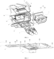
- FIG. 1 is an exploded view of an electric drive controller according to an embodiment of the present disclosure
- FIG. 2 is an exploded view of the electric drive controller shown in FIG. 1 , being viewed from another viewing angle.
- the present disclosure provides an electric drive controller.
- the electric drive controller includes a controller box 1 and electronic components disposed inside the controller box 1.
- the controller box 1 includes a closed cavity 11, a plug-connection hole 12 communicated with the closed cavity 11, and a cover body 13 covering and sealing the closed cavity 11.
- the closed cavity 11 is defined inside the controller box 1 and isolated from other components in the controller box 1.
- the above-described electronic components include a high-voltage bus perforation connector 2.
- the high-voltage bus perforation connector 2 includes an interface end portion 21 to be connected with other electronic components.
- the controller box 1 In order to prevent water vapor or other foreign matter from entering, during assembling in an assembling workshop or during after-sale detaching a bus line to replace the electric drive controller, the controller box 1 to further avoid affecting normal operation of the other electronic components, the high-voltage bus perforation connector 2 is received in the closed cavity 11 and the interface end portion 21 is received in the plug-connection hole 12.
- the controller box 1 further includes a receiving cavity 14, a connection hole 15, and an isolation plate 16.
- the receiving cavity 14 is communicated with the closed cavity 11 via the connection hole 15.
- the isolation plate 16 covers the connection hole 15.
- the electronic components further include a filter assembly 3 and a circuit board 4.
- the circuit board 4 is received in the receiving cavity 14.
- the filter assembly 3 is configured to reduce signals of a frequency different from a frequency of the electric drive controller to eliminate an effect caused by noise.
- the filter assembly 3 is received in the closed cavity 11 and is connected to the high-voltage bus perforation connector 2.
- the filter assembly 3 includes a connection end portion 31, and the connection end portion 31 is mounted in the wire through-hole and connected to the circuit board 4.
- an isolation sealing ring 5b is received in the connection hole 15, and the isolation plate 16 is mounted in the connection hole 15.
- the isolation sealing ring 5b sleeves peripheral end edges of the isolation plate 16 and abuts against a hole wall of the connection hole 15 and the peripheral end edges of the isolation plate 16. Understandably, the isolation sealing ring 5b has certain elasticity and can withstand certain compression.
- the isolation sealing ring 5b is disposed at the peripheral end edges of the isolation plate 16, and the isolation plate 16 is mounted inside the connection hole 15. In this way, the isolation sealing ring 5b abuts against the hole wall of the connection hole 15 and the peripheral end edges of the isolation plate 16, enabling the isolation plate 16 to cover and seal the connection hole 15 more tightly.
- the controller box 1 In order to securely fix the isolation plate 16 inside the controller box 1, the controller box 1 is arranged with a stop step 17 at a connection point where the connection hole 15 and the closed cavity 11 are connected to each other. During assembling, the isolation plate 16 is fixed to the stop step 17 and covers the connection hole 15.
- the controller box 1 is further arranged with another stop step 17 at a connection point where the connection hole 15 and the receiving cavity 14 are connected to each other.
- the isolation plate 16 includes a first sub-plate 161 and a second sub-plate 162.
- the first sub-panel 161 is fixed to the another stop step 17, and the second sub-panel 162 is fixed to the stop step 17. That is, each of the connection point where the connection hole 15 is connected to the closed cavity 11 and the connection point where the connection hole 15 is connected to the receiving cavity 14 is arranged with one stop step 17, and the stop step 17 and the another stop step 17 are connected to each other.
- the first sub-panel 161 is fixed to the another stop step 17, and the second sub-panel 162 is fixed to the stop step 17, and the isolation sealing ring 5b is disposed between the first sub-plate 161 and the second sub-plate 162 to abut against the first sub-plate 161 and the second sub-plate 162, such that covering performance that the isolation plate covers the closed cavity 11 is improved.
- FIG. 3 is an enlarged view of a partial structure of the electric drive controller shown in FIG. 1 ; and FIG. 4 is a top view of the partial structure of the electric drive controller shown in FIG. 3 .
- the circuit board 4 is arranged with a control module circuit area 41 and a drive module circuit area 42.
- the control module circuit area 41 is configured to achieve a controlling function of the electric drive controller, and the drive module circuit area 42 is configured to achieve a driving function of the electric drive controller.
- the circuit board 4 defines a plurality of fixation holes 45 located at a periphery of the circuit board 4.
- the circuit board 4 is fixedly arranged in the receiving cavity 14 via the plurality of fixation holes 45.
- the plurality of fixation holes 45 may be mated with bolts or fixation blocks to mount the circuit board in the controller box 1.
- the electric drive controller of the present disclosure further includes a plug-connection member 6, and the plug-connection member 6 is configured to connect with corresponding plug connectors of other components of the entire vehicle to achieve electrical conduction.
- the plug-connection member 6 includes a soldering pin 61 that is soldered and fixed to the circuit board 4 and connected to the interface circuit area 43.
- the plug-connection member 6 and the electrically conductive frame 44 are respectively disposed on two opposite sides of the circuit board 4.
- FIG. 5 is a structural schematic view of an electric drive system according to an embodiment of the present disclosure, and the electric drive system includes a drive motor and the electric drive controller.
- the electric drive system is provided and includes a drive motor 9 and the electric drive controller as described above.
- the drive motor 9 is connected to the electric drive controller.
- a structure of the electric drive controller has been described in detail above and will not be repeated herein.
- FIG. 6 is a cross-sectional view of the electric drive system shown in FIG. 5 , taken along a line B-B.
- the electric drive controller includes a three-phase wire copper row 8 arranged in the controller box 1.
- the three-phase wire copper row 8 includes a connection end 81 exposed from the controller box 1, and that is, the connection end 81 extends from the three-phase wire copper row 8 towards the controller box 1 to be exposed out of the controller box 1 so as to be connected with other electronic components.
- the drive motor 9 includes a motor housing 91 and a motor terminal 92 exposed out of the motor housing 91. During assembling, the motor terminal 92 is connected to the connection end 81 of the three-phase wire copper row 8.
- each of the controller box 1 and the motor housing 91 includes a respective support surface 100, i.e., each of the box body 18 of the controller box 1 and the motor housing 91 is arranged with the respective support surface 100.
- the support surface 100 of the box body 18 and the support surface 100 of the motor housing 91 support and abut against each other. Since the support surface 100 of the box body 18 and the support surface 100 of the motor housing 91 support and abut against each other, a width of the gap path is effectively reduced, such that the amount of electromagnetic radiation is reduced. Understandably, a gap between the support surface 100 of the box body 18 and the support surface 100 of the motor housing 91 is the gap path, and the blocking member 10 is received in the gap path.
- connection end 81 extends from the three-phase wire copper row 8 to be exposed out of the support surface 100 of the controller box 1. That is, the wall of the controller box 1 defines a structure similar to a through hole, such that the connection end 81 of the three-phase wire copper row 8 can extend outwardly.
- the support surface 100 of the box body 18 is arranged with a protrusion 181.
- the support surface 100 of the motor housing 91 defines a recess 911.
- the protrusion 181 on the box body 18 is received in the recess 911 of the motor housing 91.
- the electric drive controller and the drive motor 9 can be positioned and snapped through mating between the protrusion 181 and the recess 911.
- the protrusion 181 Since the protrusion 181 is received in the recess 911, the protrusion 181 provides limiting to enable assembling between the electric drive controller and the drive motor 9 to be tighter. In this way, the electric drive controller and the drive motor 9 are prevented from being loosened from each other, such that the electromagnetic radiation generated, due to current conduction, at the connection point where the connection end 81 and the motor terminal 92 are connected to each other is prevented from exceeding the standard, and the EMC leakage, which leads to the EMC of the electric drive system failing to meet the standard, is prevented.
- each the support surface 100 of the box body 18 and the support surface 100 of the motor housing 91 is a concave and convex surface, having a toothed structure, a wavy structure, or a pulsed structure.
- connection end 81 extends from the protrusion 181 to be exposed out of the box body 18. That is, the protrusion 181 and the recess 911 are disposed at the connection point where the connection end 81 and the motor terminal 92 are connected to each other.
- the above-mentioned protrusion 181 and the recess 911 may be disposed at any position of the electromagnetic radiation path along which the electromagnetic radiates outwardly from the connection point where the connection end 81 with the motor terminal 92 are connected to each other.
- the above-mentioned protrusion 181 and the recess 911 may be disposed at any position along the direction indicated by the arrow line a, taking the connection point where the connection end 81 with the motor terminal 92 are connected to each other as a starting point.
- a vehicle in still another aspect of the present disclosure, includes a battery pack, a high-voltage bus line, and the electric drive controller as described above.
- the high-voltage bus line is connected to the interface end portion 21 of the battery pack and the electric drive controller to allow the battery pack to supply power to the electric drive controller. In this way, it is ensured that the electric drive controller operates normally.
- the structure of the electric drive controller has been described in detail above and will not be repeated herein.
- the terms “an embodiment”, “some embodiments”, “an example”, “a specific example”, or “some examples” mean that specific features, mechanisms, materials, or characteristics described in an embodiment or an example are included in at least one embodiment or example of the present disclosure.
- schematic expressions of the above terms do not necessarily refer to a same embodiment or example.
- the specific features, mechanisms, materials, or characteristics described may be combined in any one or more embodiments or examples in any suitable manner.
- any ordinary skilled person in the art may combine different embodiments or examples and features of different embodiments or examples described in the present specification.
Landscapes
- Engineering & Computer Science (AREA)
- Microelectronics & Electronic Packaging (AREA)
- Power Engineering (AREA)
- Transportation (AREA)
- Mechanical Engineering (AREA)
- Casings For Electric Apparatus (AREA)
- Motor Or Generator Frames (AREA)
Applications Claiming Priority (2)
| Application Number | Priority Date | Filing Date | Title |
|---|---|---|---|
| CN202211616180.7A CN116156795A (zh) | 2022-12-12 | 2022-12-12 | 电驱控制器、电驱动系统及汽车 |
| PCT/CN2023/090392 WO2024124773A1 (zh) | 2022-12-12 | 2023-04-24 | 电驱控制器、电驱动系统及汽车 |
Publications (2)
| Publication Number | Publication Date |
|---|---|
| EP4535940A1 true EP4535940A1 (de) | 2025-04-09 |
| EP4535940A4 EP4535940A4 (de) | 2026-03-25 |
Family
ID=86361035
Family Applications (1)
| Application Number | Title | Priority Date | Filing Date |
|---|---|---|---|
| EP23901986.2A Pending EP4535940A4 (de) | 2022-12-12 | 2023-04-24 | Elektrische antriebssteuerung, elektrisches antriebssystem und kraftfahrzeug |
Country Status (5)
| Country | Link |
|---|---|
| EP (1) | EP4535940A4 (de) |
| JP (1) | JP2025526271A (de) |
| CN (1) | CN116156795A (de) |
| AU (1) | AU2023394916B2 (de) |
| WO (1) | WO2024124773A1 (de) |
Family Cites Families (18)
| Publication number | Priority date | Publication date | Assignee | Title |
|---|---|---|---|---|
| JPH06260785A (ja) * | 1993-03-04 | 1994-09-16 | Oki Electric Ind Co Ltd | 基板シールド構造 |
| JP2001189574A (ja) * | 2000-01-05 | 2001-07-10 | Calsonic Kansei Corp | 防水ケースへのグロメット取付構造 |
| JP4895968B2 (ja) * | 2007-10-05 | 2012-03-14 | 日立オートモティブシステムズ株式会社 | 電力変換装置 |
| KR200474883Y1 (ko) * | 2012-09-05 | 2014-10-22 | 엘에스산전 주식회사 | 전기 자동차 충전기 |
| US9666968B2 (en) * | 2013-01-17 | 2017-05-30 | Lear Corporation | Electrical busbar, electrical connector assembly and power converter |
| JP6011557B2 (ja) * | 2014-01-31 | 2016-10-19 | 株式会社デンソー | 駆動装置 |
| CN204119643U (zh) * | 2014-08-28 | 2015-01-21 | 大洋电机新动力科技有限公司 | 一种igbt模块及其应用的电机控制器 |
| CN105578838B (zh) * | 2014-10-16 | 2018-01-05 | 中山大洋电机股份有限公司 | 一种电机控制器 |
| JP6370243B2 (ja) * | 2015-03-06 | 2018-08-08 | 日立オートモティブシステムズ株式会社 | 電子回路装置 |
| KR102372021B1 (ko) * | 2015-10-02 | 2022-03-10 | 한온시스템 주식회사 | 전동식 압축기 |
| CN205212748U (zh) * | 2015-11-30 | 2016-05-04 | 中山大洋电机股份有限公司 | 一种电机控制器 |
| CN108075672B (zh) * | 2016-11-18 | 2019-11-22 | 比亚迪股份有限公司 | 负载控制器及具有该负载控制器的电动汽车 |
| CN108711810A (zh) * | 2018-06-15 | 2018-10-26 | 江苏德泽智能电气科技有限公司 | 一种接头器部位带插接口的密集母线槽 |
| JP6847171B2 (ja) * | 2019-07-16 | 2021-03-24 | 三菱電機株式会社 | 電子制御装置 |
| CN215436296U (zh) * | 2021-03-31 | 2022-01-07 | 上海汽车电驱动有限公司 | 一种新能源汽车用三合一电驱系统总成 |
| CN113517820A (zh) * | 2021-04-28 | 2021-10-19 | 中国第一汽车股份有限公司 | 电机控制器功率装置及电机控制器 |
| CN113525100A (zh) * | 2021-06-28 | 2021-10-22 | 浙江零跑科技股份有限公司 | 一种乘用车用电驱控制器结构 |
| CN113939119A (zh) * | 2021-09-01 | 2022-01-14 | 浙江零跑科技股份有限公司 | 一种母线输入装置 |
-
2022
- 2022-12-12 CN CN202211616180.7A patent/CN116156795A/zh active Pending
-
2023
- 2023-04-24 AU AU2023394916A patent/AU2023394916B2/en active Active
- 2023-04-24 EP EP23901986.2A patent/EP4535940A4/de active Pending
- 2023-04-24 JP JP2024577393A patent/JP2025526271A/ja active Pending
- 2023-04-24 WO PCT/CN2023/090392 patent/WO2024124773A1/zh not_active Ceased
Also Published As
| Publication number | Publication date |
|---|---|
| EP4535940A4 (de) | 2026-03-25 |
| AU2023394916A1 (en) | 2025-01-16 |
| JP2025526271A (ja) | 2025-08-13 |
| WO2024124773A1 (zh) | 2024-06-20 |
| CN116156795A (zh) | 2023-05-23 |
| AU2023394916B2 (en) | 2026-02-05 |
Similar Documents
| Publication | Publication Date | Title |
|---|---|---|
| JP3232147U (ja) | 高電圧コネクタ配置用フィルタアセンブリおよび高電圧コネクタ配置 | |
| EP1079475B1 (de) | Abgeschirmter Verbinder | |
| US12171071B2 (en) | Electronic control device | |
| US20250246727A1 (en) | Top cover assembly, battery cell, assembling method for battery cell, and electric device | |
| US11489272B2 (en) | Connector apparatus for a battery | |
| WO2016111143A1 (ja) | 蓄電ユニット | |
| US10193312B2 (en) | High frequency discharge ignition apparatus | |
| CN109560670B (zh) | 一种新能源车用水冷电机系统 | |
| JP4974153B2 (ja) | シールド端末処理構造 | |
| JP2008235189A (ja) | コネクタハウジング | |
| CN113904162A (zh) | 连接器 | |
| JP2019110042A (ja) | シールドコネクタ、及び、ワイヤハーネス | |
| JP5315912B2 (ja) | 多連装電気コネクタ | |
| JP6334359B2 (ja) | シールドコネクタの固定構造 | |
| CN109072894B (zh) | 逆变器一体型电动压缩机 | |
| AU2023394916B2 (en) | Electric drive controller, electric drive system, and vehicle | |
| JP4976185B2 (ja) | 機器用シールドコネクタ及びワイヤーハーネス | |
| JP3753706B2 (ja) | コネクタ | |
| CN209344964U (zh) | 一种新能源车用水冷电机系统 | |
| CN215345688U (zh) | 一种逆变器及电驱动桥总成 | |
| CN212114099U (zh) | 车用高压连接器和车辆 | |
| CN219019311U (zh) | 电机控制器及车辆 | |
| CN224150735U (zh) | 车灯和车辆 | |
| CN223488572U (zh) | 电力电子集成模块总成 | |
| JP7046146B1 (ja) | 電力変換装置 |
Legal Events
| Date | Code | Title | Description |
|---|---|---|---|
| STAA | Information on the status of an ep patent application or granted ep patent |
Free format text: STATUS: THE INTERNATIONAL PUBLICATION HAS BEEN MADE |
|
| PUAI | Public reference made under article 153(3) epc to a published international application that has entered the european phase |
Free format text: ORIGINAL CODE: 0009012 |
|
| STAA | Information on the status of an ep patent application or granted ep patent |
Free format text: STATUS: REQUEST FOR EXAMINATION WAS MADE |
|
| 17P | Request for examination filed |
Effective date: 20241230 |
|
| AK | Designated contracting states |
Kind code of ref document: A1 Designated state(s): AL AT BE BG CH CY CZ DE DK EE ES FI FR GB GR HR HU IE IS IT LI LT LU LV MC ME MK MT NL NO PL PT RO RS SE SI SK SM TR |
|
| RIN1 | Information on inventor provided before grant (corrected) |
Inventor name: XU, LINGYANG Inventor name: WANG, CHENLIN Inventor name: SHAN, DONGSHENG Inventor name: LIAO, YANG Inventor name: YANG, ZHICHAO Inventor name: XIE, WEI |
|
| REG | Reference to a national code |
Ref country code: DE Ref legal event code: R079 Free format text: PREVIOUS MAIN CLASS: H05K0005000000 Ipc: H05K0007140000 |
|
| RIC1 | Information provided on ipc code assigned before grant |
Ipc: H05K 7/14 20060101AFI20251126BHEP |
|
| DAV | Request for validation of the european patent (deleted) | ||
| DAX | Request for extension of the european patent (deleted) | ||
| A4 | Supplementary search report drawn up and despatched |
Effective date: 20260223 |
|
| RIC1 | Information provided on ipc code assigned before grant |
Ipc: H05K 7/14 20060101AFI20260217BHEP |