EP4535552A1 - Verfahren und vorrichtung zur herstellung einer sekundärbatterie und damit hergestellte sekundärbatterie - Google Patents
Verfahren und vorrichtung zur herstellung einer sekundärbatterie und damit hergestellte sekundärbatterie Download PDFInfo
- Publication number
- EP4535552A1 EP4535552A1 EP23846931.6A EP23846931A EP4535552A1 EP 4535552 A1 EP4535552 A1 EP 4535552A1 EP 23846931 A EP23846931 A EP 23846931A EP 4535552 A1 EP4535552 A1 EP 4535552A1
- Authority
- EP
- European Patent Office
- Prior art keywords
- electrode
- tape
- electrode tab
- tab stack
- stack
- Prior art date
- Legal status (The legal status is an assumption and is not a legal conclusion. Google has not performed a legal analysis and makes no representation as to the accuracy of the status listed.)
- Pending
Links
Images


Classifications
-
- H—ELECTRICITY
- H01—ELECTRIC ELEMENTS
- H01M—PROCESSES OR MEANS, e.g. BATTERIES, FOR THE DIRECT CONVERSION OF CHEMICAL ENERGY INTO ELECTRICAL ENERGY
- H01M50/00—Constructional details or processes of manufacture of the non-active parts of electrochemical cells other than fuel cells, e.g. hybrid cells
- H01M50/50—Current conducting connections for cells or batteries
- H01M50/531—Electrode connections inside a battery casing
- H01M50/536—Electrode connections inside a battery casing characterised by the method of fixing the leads to the electrodes, e.g. by welding
-
- B—PERFORMING OPERATIONS; TRANSPORTING
- B23—MACHINE TOOLS; METAL-WORKING NOT OTHERWISE PROVIDED FOR
- B23K—SOLDERING OR UNSOLDERING; WELDING; CLADDING OR PLATING BY SOLDERING OR WELDING; CUTTING BY APPLYING HEAT LOCALLY, e.g. FLAME CUTTING; WORKING BY LASER BEAM
- B23K26/00—Working by laser beam, e.g. welding, cutting or boring
- B23K26/0093—Working by laser beam, e.g. welding, cutting or boring combined with mechanical machining or metal-working covered by other subclasses than B23K
-
- B—PERFORMING OPERATIONS; TRANSPORTING
- B23—MACHINE TOOLS; METAL-WORKING NOT OTHERWISE PROVIDED FOR
- B23K—SOLDERING OR UNSOLDERING; WELDING; CLADDING OR PLATING BY SOLDERING OR WELDING; CUTTING BY APPLYING HEAT LOCALLY, e.g. FLAME CUTTING; WORKING BY LASER BEAM
- B23K26/00—Working by laser beam, e.g. welding, cutting or boring
- B23K26/20—Bonding
- B23K26/21—Bonding by welding
-
- H—ELECTRICITY
- H01—ELECTRIC ELEMENTS
- H01M—PROCESSES OR MEANS, e.g. BATTERIES, FOR THE DIRECT CONVERSION OF CHEMICAL ENERGY INTO ELECTRICAL ENERGY
- H01M10/00—Secondary cells; Manufacture thereof
- H01M10/04—Construction or manufacture in general
- H01M10/0404—Machines for assembling batteries
-
- H—ELECTRICITY
- H01—ELECTRIC ELEMENTS
- H01M—PROCESSES OR MEANS, e.g. BATTERIES, FOR THE DIRECT CONVERSION OF CHEMICAL ENERGY INTO ELECTRICAL ENERGY
- H01M10/00—Secondary cells; Manufacture thereof
- H01M10/04—Construction or manufacture in general
- H01M10/0481—Compression means other than compression means for stacks of electrodes and separators
-
- H—ELECTRICITY
- H01—ELECTRIC ELEMENTS
- H01M—PROCESSES OR MEANS, e.g. BATTERIES, FOR THE DIRECT CONVERSION OF CHEMICAL ENERGY INTO ELECTRICAL ENERGY
- H01M10/00—Secondary cells; Manufacture thereof
- H01M10/05—Accumulators with non-aqueous electrolyte
- H01M10/058—Construction or manufacture
- H01M10/0585—Construction or manufacture of accumulators having only flat construction elements, i.e. flat positive electrodes, flat negative electrodes and flat separators
-
- H—ELECTRICITY
- H01—ELECTRIC ELEMENTS
- H01M—PROCESSES OR MEANS, e.g. BATTERIES, FOR THE DIRECT CONVERSION OF CHEMICAL ENERGY INTO ELECTRICAL ENERGY
- H01M50/00—Constructional details or processes of manufacture of the non-active parts of electrochemical cells other than fuel cells, e.g. hybrid cells
- H01M50/10—Primary casings; Jackets or wrappings
- H01M50/172—Arrangements of electric connectors penetrating the casing
- H01M50/174—Arrangements of electric connectors penetrating the casing adapted for the shape of the cells
- H01M50/178—Arrangements of electric connectors penetrating the casing adapted for the shape of the cells for pouch or flexible bag cells
-
- H—ELECTRICITY
- H01—ELECTRIC ELEMENTS
- H01M—PROCESSES OR MEANS, e.g. BATTERIES, FOR THE DIRECT CONVERSION OF CHEMICAL ENERGY INTO ELECTRICAL ENERGY
- H01M50/00—Constructional details or processes of manufacture of the non-active parts of electrochemical cells other than fuel cells, e.g. hybrid cells
- H01M50/50—Current conducting connections for cells or batteries
- H01M50/531—Electrode connections inside a battery casing
- H01M50/54—Connection of several leads or tabs of plate-like electrode stacks, e.g. electrode pole straps or bridges
-
- H—ELECTRICITY
- H01—ELECTRIC ELEMENTS
- H01M—PROCESSES OR MEANS, e.g. BATTERIES, FOR THE DIRECT CONVERSION OF CHEMICAL ENERGY INTO ELECTRICAL ENERGY
- H01M50/00—Constructional details or processes of manufacture of the non-active parts of electrochemical cells other than fuel cells, e.g. hybrid cells
- H01M50/50—Current conducting connections for cells or batteries
- H01M50/572—Means for preventing undesired use or discharge
- H01M50/584—Means for preventing undesired use or discharge for preventing incorrect connections inside or outside the batteries
- H01M50/59—Means for preventing undesired use or discharge for preventing incorrect connections inside or outside the batteries characterised by the protection means
- H01M50/595—Tapes
-
- B—PERFORMING OPERATIONS; TRANSPORTING
- B23—MACHINE TOOLS; METAL-WORKING NOT OTHERWISE PROVIDED FOR
- B23K—SOLDERING OR UNSOLDERING; WELDING; CLADDING OR PLATING BY SOLDERING OR WELDING; CUTTING BY APPLYING HEAT LOCALLY, e.g. FLAME CUTTING; WORKING BY LASER BEAM
- B23K2101/00—Articles made by soldering, welding or cutting
- B23K2101/36—Electric or electronic devices
- B23K2101/38—Conductors
-
- H—ELECTRICITY
- H01—ELECTRIC ELEMENTS
- H01M—PROCESSES OR MEANS, e.g. BATTERIES, FOR THE DIRECT CONVERSION OF CHEMICAL ENERGY INTO ELECTRICAL ENERGY
- H01M50/00—Constructional details or processes of manufacture of the non-active parts of electrochemical cells other than fuel cells, e.g. hybrid cells
- H01M50/10—Primary casings; Jackets or wrappings
- H01M50/102—Primary casings; Jackets or wrappings characterised by their shape or physical structure
- H01M50/105—Pouches or flexible bags
-
- Y—GENERAL TAGGING OF NEW TECHNOLOGICAL DEVELOPMENTS; GENERAL TAGGING OF CROSS-SECTIONAL TECHNOLOGIES SPANNING OVER SEVERAL SECTIONS OF THE IPC; TECHNICAL SUBJECTS COVERED BY FORMER USPC CROSS-REFERENCE ART COLLECTIONS [XRACs] AND DIGESTS
- Y02—TECHNOLOGIES OR APPLICATIONS FOR MITIGATION OR ADAPTATION AGAINST CLIMATE CHANGE
- Y02E—REDUCTION OF GREENHOUSE GAS [GHG] EMISSIONS, RELATED TO ENERGY GENERATION, TRANSMISSION OR DISTRIBUTION
- Y02E60/00—Enabling technologies; Technologies with a potential or indirect contribution to GHG emissions mitigation
- Y02E60/10—Energy storage using batteries
-
- Y—GENERAL TAGGING OF NEW TECHNOLOGICAL DEVELOPMENTS; GENERAL TAGGING OF CROSS-SECTIONAL TECHNOLOGIES SPANNING OVER SEVERAL SECTIONS OF THE IPC; TECHNICAL SUBJECTS COVERED BY FORMER USPC CROSS-REFERENCE ART COLLECTIONS [XRACs] AND DIGESTS
- Y02—TECHNOLOGIES OR APPLICATIONS FOR MITIGATION OR ADAPTATION AGAINST CLIMATE CHANGE
- Y02P—CLIMATE CHANGE MITIGATION TECHNOLOGIES IN THE PRODUCTION OR PROCESSING OF GOODS
- Y02P70/00—Climate change mitigation technologies in the production process for final industrial or consumer products
- Y02P70/50—Manufacturing or production processes characterised by the final manufactured product
Definitions
- the present invention relates to an apparatus and method for manufacturing a secondary battery and a secondary battery manufactured thereby.
- the present invention relates to an apparatus and method for manufacturing a secondary battery, in which defects such as damage or disconnection of an electrode tab does not occur while the electrode tab and an electrode lead of an electrode assembly are connected through welding, and welding defects such as weak welding or excessive welding occurs are prevented from occurring to realize excellent quality, and a secondary battery manufactured thereby.
- Secondary batteries are receiving a lot of attention as an energy source in a variety of products such as mobile devices and electric vehicles. These secondary batteries are an excellent energy resource, which is capable of replacing the use of existing products using fossil fuels, and are attracting attention as an eco-friendly energy source because the secondary batteries do not generate by-products due to the energy use.
- FIG. 1 is a side view illustrating a process of connecting an electrode tab and an electrode lead using a method for manufacturing a secondary battery according to the related art.
- a process of connecting an electrode tab to an electrode lead is performed by performing a pre-welding process (see 1 in FIG. 1 ) first and then performing a main welding process (see 2 in FIG. 1 ).
- the pre-welding process (see 1 in FIG. 1 ) is a process of gathering a plurality of electrode tabs extending from an electrodes of an electrode assembly to bond the electrode tabs to each other through ultrasonic welding. As a result, an electrode tab assembly may be formed.
- the pre-welding is a method of disposing the plurality of electrode tabs between an upper horn and a lower anvil to apply ultrasonic vibration B to the horn while physically pressing through the horn and the anvil.
- the main welding process (see 2 in FIG. 1 ) is a process of bonding the electrode leads to the gathered electrode tab assembly.
- laser welding is performed using a laser welder to bond the electrode tab to the electrode lead.
- Such a method according to the related art has the following problems.
- the pre-welding method is the method in which the physical pressure is applied to the electrode tab with the horn and the anvil, and the ultrasonic vibration is applied to the horn, there is a problem of inevitably damaging the electrode tab.
- welding defects such as weak welding and excessive welding due to abnormal welding conditions such as energy, power, a welding time, and an applied pressure.
- welding defects and defects such as disconnection of the electrode tab due to a deviation in horizontality of the horn and the anvil or abnormal lamination during the welding.
- the present invention is devised to solve the above problems, and an object of the present invention is to provide an apparatus and method for manufacturing a secondary battery, in which defects such as damage or disconnection of an electrode tab does not occur while the electrode tab and an electrode lead of an electrode assembly are connected through welding, and welding defects such as weak welding or excessive welding occurs are prevented from occurring to realize excellent quality, and a secondary battery manufactured thereby.
- a method for manufacturing a secondary battery, in which a plurality of electrode tabs extending from one end of an electrode assembly formed by stacking electrodes and separators are welded to an electrode lead, according to the present invention includes: a process (a) of preparing a tape having a required size and shape; a process (b) of gathering the plurality of electrode tabs to form an electrode tab stack; a process (c) of taping the electrode tab stack with the tape; and a process (d) of welding the electrode tab stack, which is taped, to the electrode lead.
- the method may further include a cutting process (c-1) of cutting one end of the electrode tab stack, which is taped, between the process (c) and the process (d).
- the process (a) of preparing the tape may include a process of cutting the tape in a required size and shape to prepare the tape.
- the plurality of electrode tabs may be pressed or guided from upper and lower sides of the electrode tabs to gather the electrode tabs so as to form the electrode tab stack.
- the tape may be attached to each of both ends of the electrode tab stack based on a width direction of the electrode tab stack.
- the tape may be attached to surround top, side, and bottom surfaces of the electrode tab stack.
- the tape may not be attached to a portion, at which the electrode lead is to be welded, on the top and bottom surfaces of the electrode tab stack.
- the tape may be attached to each of both ends of the electrode tab stack based on a width direction of the electrode tab stack, wherein the tape may be attached to the electrode tab stack so that a surplus part protruding further outward from an end of the electrode tab stack in a width direction is formed.
- the surplus part may have a shape in which a portion and the other portion of the tape, which is disposed outside the end of the electrode tab stack in the width direction face each other to be bonded to each other.
- the electrode tab stack and the electrode lead may be welded to each other by laser welding.
- An apparatus for manufacturing a secondary battery, in which a plurality of electrode tabs extending from one end of an electrode assembly formed by stacking electrodes and separators are welded to an electrode lead includes: a tape cutting unit configured to cut a tape to a required size and shape; a tab guide configured to gather the plurality of electrode tabs so as to provide an electrode tab stack; a tape attaching machine configured to tape the cut tape on the electrode tab stack; and a laser welder configured to weld the electrode tab stack, which is taped, to the electrode lead.
- the tape attaching machine may be configured to tape the tape on the electrode tab stack, wherein the tape may be attached to surround top, side, and bottom surfaces of the electrode tab stack.
- the tape attaching machine may be configured to tape the tape on the electrode tab stack, wherein the tape may be attached to the electrode tab stack so that a surplus part protruding outward from an end of each of the electrode tabs in a width direction is provided.
- the apparatus may further include a clamping device configured to pull the surplus part disposed at each of both sides of the electrode tab stack to both sides based on the width direction of the electrode tab stack.
- a secondary battery includes: an electrode assembly provided by stacking electrodes and separators; a pouch configured to accommodate the electrode assembly in an internal space; an electrode tab stack provided by gathering a plurality of electrode tabs extending from one end of the electrode assembly and disposed inside the pouch; a tape configured to surround the electrode tab stack; and an electrode lead having one side connected to the electrode tab stack and the other side protruding to the outside of the pouch.
- the tape may be attached to each of both ends of the electrode tab stack based on a width direction of the electrode tab stack.
- the tape may be attached to each of both ends of the electrode tab stack based on a width direction of the electrode tab stack, wherein the tape may include a surplus part protruding further outward from an end of the electrode tan stack in a width direction.
- the surplus part may have a shape in which a portion and the other portion of the tape, which is disposed outside the end of the electrode tab stack in the width direction face each other to be bonded to each other.
- the defects such as the damage or disconnection of the electrode tab does not occur while the electrode tab and the electrode lead of the electrode assembly are connected through the welding, and the welding defects such as the weak welding or the excessive welding occurs are prevented from occurring to realize the excellent quality.
- FIG. 2 is a side view illustrating a process of connecting an electrode tab to an electrode lead through a method for manufacturing a secondary battery according to Embodiment 1 of the present invention.
- FIG. 3 is a side view illustrating a process of connecting an electrode tab to an electrode lead according to a modified example of Embodiment 1 of the present invention.
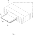
- FIG. 4 is a perspective view illustrating a state in which a tape is attached to an electrode tab stack.
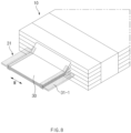
- FIG. 5 is a perspective view illustrating a state in which one end of the electrode tab stack is cut.
- a method for manufacturing a secondary battery according to Embodiment 1 of the present invention may relate to a method for manufacturing a secondary battery, in which a plurality of electrode tabs 20 extending from one end of an electrode assembly formed by stacking electrodes and separators is welded to an electrode lead 40.
- the electrode assembly 10 may be formed by alternately stacking the electrodes and the separators, and the electrode tab 20 may be a metal tab connected to each of the electrodes and protruding from one side of the electrode.
- the plurality of electrode tabs 20 may have a structure extending from one end of the electrode assembly 10.
- a stack in which the plurality of electrode tabs 20 are combined may be coupled again to the electrode lead 40 to manufacture a secondary battery.
- the method for manufacturing the secondary battery according to Embodiment 1 of the present invention may include a process (a) of preparing a tape, a process (b) of forming an electrode tab stack, a process (c) of taping the tape, and a process (d) of welding an electrode lead.
- the process (a) of preparing the tape may be a process of preparing a tape 31 having a required size and shape.
- FIG. 2 illustrates this process.
- the tape 31 may be cut using a tape cutting unit (not shown) that cuts the tape 31.
- the tape 31 may be prepared by cutting the tape 31 into the required size and shape using the tape cutting unit.
- FIG. 2 illustrates the tape 31 in which the cutting is completed.
- the tape 31 having the required size and shape may mean that the tape 31 has a size and shape required to attach the tape 31 so that the electrode tabs 20 are bundled in a state in which the electrode tabs 20 are gathered together.
- the process (a) of cutting and preparing the tape 31 may not necessarily have to be performed first and may be performed in any process as long as the process is performed only before the process (c) of taping the tape, which will be described below.
- the process (b) of forming the electrode tab stack may be a process of forming the electrode tab stack 30 by gathering the plurality of electrode tabs 20.
- (b) of FIG. 2 illustrates this process.
- This process may be performed using a tab guide 110 that gathers the plurality of electrode tabs 20 to form the electrode tab stack 30.
- the tab guide 110 may move downward from upper and lower portions of the electrode tab 20 in a direction of the electrode tab 20 to gather the electrode tabs 20.
- the tab guide 110 may press or guide the plurality of electrode tabs 20 from upper and lower sides of the electrode tabs 20 to gather the electrode tabs 20, thereby forming the electrode tab stack 30.
- an end of the tab guide 110 may have a rounded shape. This shape may prevent the electrode tabs 20 from being damaged while the tab guide 110 vertically applies a pressure to the plurality of electrode tabs 20 to gather the electrode tabs 20.
- the process (c) of taping the tape may be a process of taping the tape 31 to the electrode tab stack 30.
- This process may be a process in which the stack 30 of the gathered electrode tabs is maintained in a stable shape without moving or being disturbed. This process may be performed to gather the electrode tabs 20 so as to facilitate welding in the later welding process of the electrode lead 40.
- FIG. 4 illustrates a state in which the tape 31 is attached to the electrode tab stack 30 in the process (c).
- the tape 31 may be attached to each of both ends of the electrode tab stack 30 based on a width direction W of the electrode tab stack 30.
- the tape 31 may be attached to both the ends and also may be attached while surrounding top, side, and bottom surfaces of the electrode tab stack 30.
- the electrode tabs 20 may be attached in a tight state in which tension is applied or may be attached with appropriate strength so as not to be too tight.
- the tape 31 may be attached to a horizontal portion of a portion at which the electrode tabs 20 are gathered and may also be partially attached to an inclined portion extending from the horizontal portion toward the electrode assembly.
- a fundamental function of the tape attaching machine 120 may be a function of attaching the cut tape 31 to the electrode tab 20, but the tape attaching machine 120 may also be configured to have a function of cutting the tape 31.
- the tape attaching machine 120 may also function as a tape cutting unit.
- the operation may be simplified and efficient. That is, after completing the cutting of the tape 31, the user may holds the tape 31 as it is without the need to move to another position and then may attach the tape to the electrode tab 20 to realize significantly efficient operation.
- the processes (b) and (c) may be performed separately, but may also be performed together. That is, a more efficient and effective process may be possible if the process (b) of forming the electrode tab stack and the process (c) of taping the tape are performed at the same time. That is, as illustrated in (c) of FIG. 3 , the tab guide 110 may press the electrode tabs 20, gather the electrode tabs 20, and fix the electrode tabs 20, and then, the tape attaching machine 120 may attach the tape 31 to the gathered electrode tab stack 30 to realize more accurate taping.
- the process (d) of welding the electrode tab stack and the electrode lead may be a process of welding the taped electrode tab stack 30 and the electrode lead 40, which overlap each other, using a welder. This process may be a process of bonding the electrode tab stack 30 to the electrode lead 40 by the welding.
- the process (d) of welding the electrode lead 40 may be a process of laser-welding the electrode tab stack 30 and the electrode lead 40 through the laser welding.
- FIG. 2 illustrates this process. This process may be performed using the laser welder 130, which is a device that irradiates welding laser to the electrode tab stack 30 and the electrode lead 40.
- the welding area A on which the laser welding is performed may be an area on which the tape 31 is not attached. That is, as illustrated in FIG. 6 , the welding area A may be a central area of the top surface of the electrode tab stack 30.
- the electrode lead 40 is not limited to being welded to the top surface of the electrode tab stack 30, and the electrode lead 40 may also be welded to the bottom surface of the electrode tab stack 30.
- the tape 31 may be used to manufacture the secondary battery without damaging the electrode tab 20.
- problems such as welding defects caused by the ultrasonic welding may be fundamentally solved. For example, the welding defects due to deviation in horizontality of a horn and an anvil or abnormal stack during the welding, and disconnection defects of the electrode tab 20 may not occur.
- the ultrasonic welding is not used, various problems caused by using the ultrasonic welder may not occur.
- the electrode tabs 20 may be gathered quickly and efficiently to efficiently perform main welding of the electrode lead 40 and the electrode tab 20.
- the electrode tabs 20 may be gathered to secure a length margin of the electrode tabs 2 well.
- Embodiment 1 of the present invention may be implemented in an additional modified form.
- FIG. 3 is a side view illustrating a process of connecting an electrode tab 20 to an electrode lead 40 according to a modified example of Embodiment 1 of the present invention.
- a cutting process c-1 may be further performed between the processes (c) and (d) .
- the cutting process c-1 may be a process of cutting one end of the taped electrode tab stack 30.
- (c-1) of FIG. 3 illustrates this process.
- the remaining processes are the same as Embodiment 1 of FIG. 2 , except that the cutting process c-1 is further performed between the process (c) of taping the tape and the process (d) of welding the electrode tab stack to the electrode lead.
- the cutting process c-1 may be performed using a cutter 140, which cuts one end of the electrode tab stack 30 for which the taping is completed by the tape attaching machine 120 to an appropriate length.
- FIG. 5 illustrates a state in which one end of the electrode tab stack is cut by the cutter 140.
- FIG. 5 illustrates a shape in which the electrode tab stack 30 is neatly cut along a cutting line L.
- a central area of a top surface of the electrode tab 20 to which the tape 31 is not attached may be a laser welding area A on which the electrode lead 40 is welded. After the cutting operation, welding may be performed accurately on the welding area A.
- An apparatus for manufacturing a secondary battery may be required to perform the method for manufacturing the secondary battery according to Embodiment 1 of the present invention.
- the apparatus for manufacturing the secondary battery may be an apparatus for manufacturing a secondary battery, in which a plurality of electrode tabs 20 extending from one end of an electrode assembly formed by stacking electrodes and separators is welded to an electrode lead 40.
- the apparatus for manufacturing the secondary battery for performing the method for manufacturing the secondary battery according to Embodiment 1 of the present invention may include a tape cutting unit (not shown), a tab guide 110, a tape attaching machine 120, and a laser welder 130.
- the tape cutting unit may be configured to cut a tape 31 into a required size and shape.
- the tab guide 110 may be configured to gather a plurality of electrode tabs 20 to provide an electrode tab stack 30.
- the tape attaching machine 120 may be configured to tape the cut tape 31 to the electrode tab stack 30.
- the laser welder 130 may be configured to weld the taped electrode tab stack 30 to the electrode lead 40.
- the tape attaching machine 120 may also function as a tape cutting unit.
- the apparatus for manufacturing the secondary battery may further include a cutter 140 for cutting one end of the electrode tab stack 30 on which the taping is completed by the tape attaching machine 120.
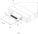
- FIG. 6 is a perspective view illustrating an internal configuration of a secondary battery according to Embodiment 2 of the present invention.
- Embodiment 2 of the present invention is different from Embodiment 1 in that it relates to a secondary battery manufactured by the method for manufacturing the secondary battery according to Embodiment 1.
- Embodiment 1 The contents that are duplicated with Embodiment 1 will be omitted as much as possible, and Embodiment 2 will be described with a focus on the differences. That is, it is obvious that contents that are not described in Embodiment 2 may be regarded as the contents of Embodiment 1 if necessary.
- a secondary battery according to Embodiment 2 of the present invention may include an electrode assembly 10, a pouch, an electrode tab stack 30, an electrode lead 40, and a tape 31.
- the electrode assembly 10 may be a stack provided by stacking electrodes and separators.
- the pouch (not shown) may be configured to accommodate the electrode assembly 10 in an internal space.
- the electrode tab stack 30 may be provided by gathering the plurality of electrode tabs 20 that extend from one end of the electrode assembly 10 and are disposed inside the pouch.
- the tape 31 may be configured to surround the electrode tab stack 30. Here, the tape 31 may be attached to each of both ends of the electrode tab stack 30 based on a width direction W of the electrode tab stack 30.
- the tape 31 When attached to both the ends, the tape 31 may be attached while surrounding top, side, and bottom surfaces of the electrode tab stack 30.
- the electrode tabs 20 may be attached in a tight state in which tension is applied or may be attached with appropriate strength so as not to be too tight.
- the tape 31 may be attached to a horizontal portion of a portion at which the electrode tabs 20 are gathered and may also be partially attached to an inclined portion extending from the horizontal portion toward the electrode. That is, a thickness of the electrode tab stack 30 may be constant in the horizontal portion, but may be thick in the inclined portion, and the tape 31 may be attached to portions of the horizontal portion and the inclined portion.
- the tape 31 may not be attached to top and bottom surfaces of the electrode tab stack 30 on which the electrode lead 40 is to be welded.
- a welding area A on which the electrode lead 40 is welded may be formed at the portion at which the tape 31 is not attached (see FIG. 6 ). Since an area on which the tape 31 is attached is an unsuitable surface for welding, the tape 31 may not be attached to the surface to be welded.
- the electrode lead 40 may have one side connected to the electrode tab stack 30 and the other side protruding to the outside of the pouch (not shown).
- One side of the electrode lead 40 may be connected to the electrode tab stack 30 in the welding area A through laser welding.
- the welding may be performed excluding an area on which a lead film 41 is to be attached.
- the secondary battery according to Embodiment 2 of the present invention as described above may be a secondary battery having excellent quality as various effects of the invention described in foregoing Embodiment 1 are expressed.
- FIG. 7 is a side view illustrating a process of connecting an electrode tab to an electrode lead through a method for manufacturing a secondary battery according to Embodiment 3 of the present invention.
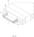
- FIG. 8 is a perspective view illustrating a state in which a tape is attached to an electrode tab stack according to Embodiment 3 of the present invention.
- FIG. 9 is a cross-sectional view illustrating a principle in which a surplus part of a tape is generated according to Embodiment 3 of the present invention.
- FIG. 10 is a perspective view illustrating a state in which one end of the electrode tab stack is cut according to Embodiment 3 of the present invention.
- Embodiment 3 is different from Embodiments 1 and 2 in that, when attaching the tape to the electrode tab stack, the tape is attached so that a surplus part is disposed on each of both sides of the electrode tab.
- Embodiment 3 The contents that are duplicated with Embodiments 1 and 2 will be omitted as much as possible, and Embodiment 3 will be described with a focus on the differences. That is, it is obvious that the contents that are not described in Embodiment 3 may be supplemented as contents of Embodiments 1 and 2 if necessary.
- a method for manufacturing a secondary battery according to Embodiment 3 of the present invention may also relate to a method for manufacturing a secondary battery, in which a plurality of electrode tabs 20 extending from one end of an electrode assembly formed by stacking electrodes and separators is welded to an electrode lead 40.
- a clamping device 150 that pulls the surplus part 31-1 disposed at both sides of the electrode tab stack to both sides based on the width direction W of the electrode tab stack 30 may be further provided.
- the clamping device 150 may be mainly used in the process of welding the electrode lead 40, which will be described below, but may also be used in the taping process (c) to tightly attach the tape 31.
Landscapes
- Chemical & Material Sciences (AREA)
- Chemical Kinetics & Catalysis (AREA)
- Electrochemistry (AREA)
- General Chemical & Material Sciences (AREA)
- Engineering & Computer Science (AREA)
- Physics & Mathematics (AREA)
- Optics & Photonics (AREA)
- Manufacturing & Machinery (AREA)
- Plasma & Fusion (AREA)
- Mechanical Engineering (AREA)
- Connection Of Batteries Or Terminals (AREA)
- Sealing Battery Cases Or Jackets (AREA)
Applications Claiming Priority (3)
| Application Number | Priority Date | Filing Date | Title |
|---|---|---|---|
| KR20220093537 | 2022-07-27 | ||
| KR1020230093435A KR20240015577A (ko) | 2022-07-27 | 2023-07-18 | 이차전지 제조방법, 제조장치 및 그에 의해 제조된 이차전지 |
| PCT/KR2023/010615 WO2024025272A1 (ko) | 2022-07-27 | 2023-07-21 | 이차전지 제조방법, 제조장치 및 그에 의해 제조된 이차전지 |
Publications (2)
| Publication Number | Publication Date |
|---|---|
| EP4535552A1 true EP4535552A1 (de) | 2025-04-09 |
| EP4535552A4 EP4535552A4 (de) | 2025-10-01 |
Family
ID=89706866
Family Applications (1)
| Application Number | Title | Priority Date | Filing Date |
|---|---|---|---|
| EP23846931.6A Pending EP4535552A4 (de) | 2022-07-27 | 2023-07-21 | Verfahren und vorrichtung zur herstellung einer sekundärbatterie und damit hergestellte sekundärbatterie |
Country Status (5)
| Country | Link |
|---|---|
| US (1) | US20260011882A1 (de) |
| EP (1) | EP4535552A4 (de) |
| JP (1) | JP2025521709A (de) |
| CN (1) | CN119422285A (de) |
| WO (1) | WO2024025272A1 (de) |
Family Cites Families (11)
| Publication number | Priority date | Publication date | Assignee | Title |
|---|---|---|---|---|
| KR100377920B1 (ko) * | 2001-03-28 | 2003-03-29 | 주식회사 에스에프에이 | 밀폐 테이프가 부착된 전극 탭의 제조방법 및 그 장치 |
| KR101095343B1 (ko) * | 2005-11-30 | 2011-12-16 | 주식회사 엘지화학 | 개선된 구조의 젤리-롤 및 이를 포함하는 이차전지 |
| JP2016186868A (ja) * | 2015-03-27 | 2016-10-27 | ブラザー工業株式会社 | 電池 |
| JP6582500B2 (ja) * | 2015-03-31 | 2019-10-02 | 株式会社Gsユアサ | 蓄電素子 |
| CN108475756B (zh) * | 2016-02-29 | 2021-07-09 | 松下知识产权经营株式会社 | 电极体的制造方法以及非水电解质二次电池的制造方法 |
| JP2019207794A (ja) * | 2018-05-29 | 2019-12-05 | 株式会社豊田自動織機 | 蓄電装置の製造方法 |
| KR102883837B1 (ko) * | 2019-11-20 | 2025-11-11 | 주식회사 엘지에너지솔루션 | 복수 금속 시트가 결합된 전극 리드를 포함하는 이차전지 및 이의 제조방법 |
| KR20220052459A (ko) * | 2020-10-21 | 2022-04-28 | 주식회사 엘지에너지솔루션 | 전극 탭 고정부를 포함하는 용접장치 및 이를 이용한 전극 탭 용접 방법 |
| TW202218491A (zh) | 2020-10-27 | 2022-05-01 | 日商友華股份有限公司 | 可撓性基板、檢查治具 |
| KR102764345B1 (ko) | 2020-12-28 | 2025-02-07 | 삼성전자주식회사 | 패키지 구조 |
| KR102572385B1 (ko) * | 2021-01-08 | 2023-09-01 | 동원시스템즈 주식회사 | 2차 전지용 전극탭 부착체 제조 방법 |
-
2023
- 2023-07-21 WO PCT/KR2023/010615 patent/WO2024025272A1/ko not_active Ceased
- 2023-07-21 EP EP23846931.6A patent/EP4535552A4/de active Pending
- 2023-07-21 CN CN202380049582.XA patent/CN119422285A/zh active Pending
- 2023-07-21 JP JP2024576725A patent/JP2025521709A/ja active Pending
- 2023-07-21 US US18/881,966 patent/US20260011882A1/en active Pending
Also Published As
| Publication number | Publication date |
|---|---|
| EP4535552A4 (de) | 2025-10-01 |
| US20260011882A1 (en) | 2026-01-08 |
| WO2024025272A1 (ko) | 2024-02-01 |
| CN119422285A (zh) | 2025-02-11 |
| JP2025521709A (ja) | 2025-07-10 |
Similar Documents
| Publication | Publication Date | Title |
|---|---|---|
| KR102920238B1 (ko) | 집전 구조가 개선된 이차전지 | |
| US11469481B2 (en) | Battery unit and manufacturing method thereof, and battery module | |
| JP5844052B2 (ja) | 積層式電池およびその製造方法 | |
| CN102412380B (zh) | 电池和用于电池的超声波焊接方法 | |
| US10050299B2 (en) | Manufacturing method of electric storage apparatus, auxiliary plate for ultrasonic welding, and electric storage apparatus | |
| US20140186671A1 (en) | Secondary cell | |
| CN101908652B (zh) | 密闭型电池及密闭型电池的制造方法 | |
| CN102969477B (zh) | 锂离子电池及其极耳与极柱的连接件 | |
| CN108352492B (zh) | 二次电池电芯 | |
| JP2013178997A (ja) | 二次電池 | |
| CN204946995U (zh) | 二次电池电芯及其卷绕成型系统 | |
| US20160293928A1 (en) | Prismatic secondary battery | |
| KR20170100333A (ko) | 배터리 셀 및 이러한 배터리 셀의 제조 방법 | |
| KR20140088343A (ko) | 분리막들이 상호 접합된 전극조립체 및 이를 포함하는 이차전지 | |
| JP2012190636A (ja) | 電池および電池の製造方法 | |
| CN115732864A (zh) | 电池、电极板的制造方法及电池的制造方法 | |
| JP2025038225A (ja) | 電圧検出装置及び電池モジュール | |
| JP2014102875A (ja) | 積層式電池 | |
| JP2007053002A (ja) | 電池の製造方法 | |
| KR20240015577A (ko) | 이차전지 제조방법, 제조장치 및 그에 의해 제조된 이차전지 | |
| EP4535552A1 (de) | Verfahren und vorrichtung zur herstellung einer sekundärbatterie und damit hergestellte sekundärbatterie | |
| KR20220068555A (ko) | 레이저 용접법을 이용하여 배터리 셀을 제조하는 방법 및 이를 이용하여 제조된 배터리 셀 | |
| JP4120353B2 (ja) | 二次電池及び該製造方法 | |
| KR101678810B1 (ko) | 용접봉 정렬용 홀을 포함하고 있는 지그를 구비한 용접 장치 | |
| JP7614233B2 (ja) | 電池モジュール |
Legal Events
| Date | Code | Title | Description |
|---|---|---|---|
| STAA | Information on the status of an ep patent application or granted ep patent |
Free format text: STATUS: THE INTERNATIONAL PUBLICATION HAS BEEN MADE |
|
| PUAI | Public reference made under article 153(3) epc to a published international application that has entered the european phase |
Free format text: ORIGINAL CODE: 0009012 |
|
| STAA | Information on the status of an ep patent application or granted ep patent |
Free format text: STATUS: REQUEST FOR EXAMINATION WAS MADE |
|
| 17P | Request for examination filed |
Effective date: 20250106 |
|
| AK | Designated contracting states |
Kind code of ref document: A1 Designated state(s): AL AT BE BG CH CY CZ DE DK EE ES FI FR GB GR HR HU IE IS IT LI LT LU LV MC ME MK MT NL NO PL PT RO RS SE SI SK SM TR |
|
| A4 | Supplementary search report drawn up and despatched |
Effective date: 20250903 |
|
| RIC1 | Information provided on ipc code assigned before grant |
Ipc: H01M 50/595 20210101AFI20250828BHEP Ipc: H01M 50/536 20210101ALI20250828BHEP Ipc: H01M 50/46 20210101ALI20250828BHEP Ipc: H01M 50/105 20210101ALI20250828BHEP Ipc: H01M 10/0585 20100101ALI20250828BHEP Ipc: H01M 50/178 20210101ALI20250828BHEP Ipc: H01M 50/54 20210101ALI20250828BHEP Ipc: H01M 10/04 20060101ALI20250828BHEP |
|
| DAV | Request for validation of the european patent (deleted) | ||
| DAX | Request for extension of the european patent (deleted) |