EP4534846A2 - Vakuumpumpe und verfahren zur bestimmung der form eines roots-rotors - Google Patents
Vakuumpumpe und verfahren zur bestimmung der form eines roots-rotors Download PDFInfo
- Publication number
- EP4534846A2 EP4534846A2 EP25159220.0A EP25159220A EP4534846A2 EP 4534846 A2 EP4534846 A2 EP 4534846A2 EP 25159220 A EP25159220 A EP 25159220A EP 4534846 A2 EP4534846 A2 EP 4534846A2
- Authority
- EP
- European Patent Office
- Prior art keywords
- roots
- rotor
- roots rotor
- rotors
- clearances
- Prior art date
- Legal status (The legal status is an assumption and is not a legal conclusion. Google has not performed a legal analysis and makes no representation as to the accuracy of the status listed.)
- Pending
Links
Images





Classifications
-
- F—MECHANICAL ENGINEERING; LIGHTING; HEATING; WEAPONS; BLASTING
- F04—POSITIVE - DISPLACEMENT MACHINES FOR LIQUIDS; PUMPS FOR LIQUIDS OR ELASTIC FLUIDS
- F04C—ROTARY-PISTON, OR OSCILLATING-PISTON, POSITIVE-DISPLACEMENT MACHINES FOR LIQUIDS; ROTARY-PISTON, OR OSCILLATING-PISTON, POSITIVE-DISPLACEMENT PUMPS
- F04C18/00—Rotary-piston pumps specially adapted for elastic fluids
- F04C18/08—Rotary-piston pumps specially adapted for elastic fluids of intermeshing-engagement type, i.e. with engagement of co-operating members similar to that of toothed gearing
- F04C18/12—Rotary-piston pumps specially adapted for elastic fluids of intermeshing-engagement type, i.e. with engagement of co-operating members similar to that of toothed gearing of other than internal-axis type
- F04C18/126—Rotary-piston pumps specially adapted for elastic fluids of intermeshing-engagement type, i.e. with engagement of co-operating members similar to that of toothed gearing of other than internal-axis type with radially from the rotor body extending elements, not necessarily co-operating with corresponding recesses in the other rotor, e.g. lobes, Roots type
-
- F—MECHANICAL ENGINEERING; LIGHTING; HEATING; WEAPONS; BLASTING
- F01—MACHINES OR ENGINES IN GENERAL; ENGINE PLANTS IN GENERAL; STEAM ENGINES
- F01C—ROTARY-PISTON OR OSCILLATING-PISTON MACHINES OR ENGINES
- F01C21/00—Component parts, details or accessories not provided for in groups F01C1/00 - F01C20/00
- F01C21/08—Rotary pistons
-
- F—MECHANICAL ENGINEERING; LIGHTING; HEATING; WEAPONS; BLASTING
- F04—POSITIVE - DISPLACEMENT MACHINES FOR LIQUIDS; PUMPS FOR LIQUIDS OR ELASTIC FLUIDS
- F04C—ROTARY-PISTON, OR OSCILLATING-PISTON, POSITIVE-DISPLACEMENT MACHINES FOR LIQUIDS; ROTARY-PISTON, OR OSCILLATING-PISTON, POSITIVE-DISPLACEMENT PUMPS
- F04C18/00—Rotary-piston pumps specially adapted for elastic fluids
- F04C18/08—Rotary-piston pumps specially adapted for elastic fluids of intermeshing-engagement type, i.e. with engagement of co-operating members similar to that of toothed gearing
- F04C18/082—Details specially related to intermeshing engagement type pumps
- F04C18/084—Toothed wheels
-
- F—MECHANICAL ENGINEERING; LIGHTING; HEATING; WEAPONS; BLASTING
- F04—POSITIVE - DISPLACEMENT MACHINES FOR LIQUIDS; PUMPS FOR LIQUIDS OR ELASTIC FLUIDS
- F04C—ROTARY-PISTON, OR OSCILLATING-PISTON, POSITIVE-DISPLACEMENT MACHINES FOR LIQUIDS; ROTARY-PISTON, OR OSCILLATING-PISTON, POSITIVE-DISPLACEMENT PUMPS
- F04C25/00—Adaptations of pumps for special use of pumps for elastic fluids
- F04C25/02—Adaptations of pumps for special use of pumps for elastic fluids for producing high vacuum
-
- F—MECHANICAL ENGINEERING; LIGHTING; HEATING; WEAPONS; BLASTING
- F04—POSITIVE - DISPLACEMENT MACHINES FOR LIQUIDS; PUMPS FOR LIQUIDS OR ELASTIC FLUIDS
- F04C—ROTARY-PISTON, OR OSCILLATING-PISTON, POSITIVE-DISPLACEMENT MACHINES FOR LIQUIDS; ROTARY-PISTON, OR OSCILLATING-PISTON, POSITIVE-DISPLACEMENT PUMPS
- F04C29/00—Component parts, details or accessories of pumps or pumping installations, not provided for in groups F04C18/00 - F04C28/00
-
- G—PHYSICS
- G06—COMPUTING OR CALCULATING; COUNTING
- G06F—ELECTRIC DIGITAL DATA PROCESSING
- G06F17/00—Digital computing or data processing equipment or methods, specially adapted for specific functions
- G06F17/10—Complex mathematical operations
-
- G—PHYSICS
- G06—COMPUTING OR CALCULATING; COUNTING
- G06F—ELECTRIC DIGITAL DATA PROCESSING
- G06F30/00—Computer-aided design [CAD]
- G06F30/10—Geometric CAD
- G06F30/17—Mechanical parametric or variational design
-
- F—MECHANICAL ENGINEERING; LIGHTING; HEATING; WEAPONS; BLASTING
- F04—POSITIVE - DISPLACEMENT MACHINES FOR LIQUIDS; PUMPS FOR LIQUIDS OR ELASTIC FLUIDS
- F04C—ROTARY-PISTON, OR OSCILLATING-PISTON, POSITIVE-DISPLACEMENT MACHINES FOR LIQUIDS; ROTARY-PISTON, OR OSCILLATING-PISTON, POSITIVE-DISPLACEMENT PUMPS
- F04C2220/00—Application
- F04C2220/10—Vacuum
-
- F—MECHANICAL ENGINEERING; LIGHTING; HEATING; WEAPONS; BLASTING
- F04—POSITIVE - DISPLACEMENT MACHINES FOR LIQUIDS; PUMPS FOR LIQUIDS OR ELASTIC FLUIDS
- F04C—ROTARY-PISTON, OR OSCILLATING-PISTON, POSITIVE-DISPLACEMENT MACHINES FOR LIQUIDS; ROTARY-PISTON, OR OSCILLATING-PISTON, POSITIVE-DISPLACEMENT PUMPS
- F04C2240/00—Components
- F04C2240/20—Rotors
-
- F—MECHANICAL ENGINEERING; LIGHTING; HEATING; WEAPONS; BLASTING
- F04—POSITIVE - DISPLACEMENT MACHINES FOR LIQUIDS; PUMPS FOR LIQUIDS OR ELASTIC FLUIDS
- F04C—ROTARY-PISTON, OR OSCILLATING-PISTON, POSITIVE-DISPLACEMENT MACHINES FOR LIQUIDS; ROTARY-PISTON, OR OSCILLATING-PISTON, POSITIVE-DISPLACEMENT PUMPS
- F04C2250/00—Geometry
- F04C2250/20—Geometry of the rotor
Definitions
- a process gas is introduced into a process chamber to perform a certain type of process, such as etching process or CVD process.
- the process gas that has been introduced into the process chamber is exhausted by a vacuum pump.
- the vacuum pump used in these manufacturing processes that require high cleanliness is so-called dry vacuum pump that does not use oil in its gas flow passage.
- dry vacuum pump is a positive-displacement vacuum pump having a pair of Roots rotors in a rotor chamber which are rotated in opposite directions to deliver the gas.
- Patent document 1 Japanese laid-open patent publication No. 1-077782
- a process gas may contain particles of by-products. Such particles flow into the vacuum pump along with the process gas. Moreover, depending on conditions in the vacuum pump (e.g., temperature, pressure), particles may be generated in the vacuum pump after the process gas flows into the vacuum pump. Most of the particles are discharged from the vacuum pump along with the process gas, but some of the particles remain in the rotor chamber and gradually accumulate in the rotor chamber. In particular, when convex and concave surfaces of two opposing Roots rotors are in surface contact (technically, the Roots rotors are in non-contact in reality), there is no place for the particles to escape. As a result, the particles are strongly sandwiched between the convex and concave surfaces of the Roots rotors, thus possibly hindering the rotation of the Roots rotors.
- the present invention provides a vacuum pump capable of preventing particles from being caught between Roots rotors and capable of maintaining smooth rotation of the Roots rotors.
- the invention further provides a method of determining a shape of such Roots rotors.
- a vacuum pump comprising: a pump casing having at least one rotor chamber therein; and a first Roots rotor and a second Roots rotor arranged in parallel in the rotor chamber, wherein each of the first Roots rotor and the second Roots rotor has an involute side surface having a shape of an involute curve, an arcuate convex surface coupled to an outer end of the involute side surface, and an arcuate concave surface coupled to an inner end of the involute side surface, and a radius of curvature of the arcuate convex surface is smaller than a radius of curvature of the arcuate concave surface.
- each of the arcuate convex surface and the arcuate concave surface is longer than the involute side surface.
- a width of a space formed between the arcuate convex surface and the arcuate concave surface when facing each other increases with a distance from a position of a minimum clearance between the arcuate convex surface and the arcuate concave surface.
- the radius of curvature of the arcuate convex surface is 0.2 to 0.9 times the radius of curvature of the arcuate concave surface.
- a method of determining a shape of a Roots rotor comprising: generating, by an arithmetic system, multiple candidates for the Roots rotor each having a shape that satisfies specifications of the Roots rotor while changing the specifications of the Roots rotor; calculating, by the arithmetic system, multiple clearances between a pair of Roots rotors corresponding to multiple rotation angles of the pair of Roots rotors having a shape of one of the multiple candidates; determining a maximum clearance among the multiple clearances; repeating calculating of the multiple clearances and determining of the maximum clearance for the multiple candidates to determine multiple maximum clearances corresponding to the multiple candidates; and determining a shape of the Roots rotor of a candidate corresponding to a smallest maximum clearance among the multiple maximum clearances.
- the method further comprises calculating additional clearances corresponding to additional rotation angles by performing interpolation for the multiple clearances corresponding to the multiple rotation angles, wherein the maximum clearance is determined from among the multiple clearances and the additional clearances.
- the Roots rotor 8 and the rotational shaft 11 may be an integral structure.
- the Roots rotor 9 and the rotational shaft 12 may be an integral structure.
- the electric motor 2 is coupled to one of the rotational shafts 11 and 12. In one embodiment, a pair of electric motors 2 may be coupled to the rotational shafts 11 and 12, respectively.
- the rotational shafts 11 and 12 are rotatably supported by bearings 17 held on the side wall 6A of the pump casing 6 and bearings 18 held on other side wall 6B of the pump casing 6.
- the electric motor 2 includes a motor housing 22 located outwardly of the side wall 6B of the pump casing 6, and a motor rotor 2A and a motor stator 2B arranged in the motor housing 22.
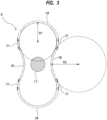
- FIG. 3 is an enlarged view of the Roots rotor 8.
- the Roots rotor 8 includes an involute side surface 31 having a shape of an involute curve, an arcuate convex surface 34 coupled to an outer end of the involute side surface 31, and an arcuate concave surface 36 coupled to an inner end of the involute side surface 31.
- the Roots rotor 8 is a so-called two-lobe Roots rotor having two protrusions. Therefore, the Roots rotor 8 has two arcuate convex surfaces 34, four involute side surfaces 31, and two arcuate concave surfaces 36.
- the two arcuate convex surfaces 34 are coupled to the outer ends of the four involute side surfaces 31, and the two arcuate concave surfaces 36 are coupled to the inner ends of the four involute side surfaces 31.
- Each of the arcuate convex surface 34 and the arcuate concave surface 36 is longer than the involute side surface 31.
- a radius of curvature R1 of the arcuate convex surface 34 is smaller than a radius of curvature R2 of the arcuate concave surface 36.
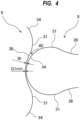
- the radius of curvature R1 of the arcuate convex surface 34 is 0.2 to 0.9 times the radius of curvature R2 of the arcuate concave surface 36. Therefore, as shown in FIG.
- the minimum clearance G1min is formed between one point on the arcuate convex surface 34 of the Roots rotor 8 and one point on the arcuate concave surface 36 of the Roots rotor 9, and a clearance between the Roots rotors 8 and 9 gradually increases on both sides of the minimum clearance G1min. Therefore, the particles are less likely to be sandwiched between the arcuate convex surface 34 of the Roots rotor 8 and the arcuate concave surface 36 of the Roots rotor 9. As a result, the Roots rotors 8 and 9 can maintain smooth rotation.
- FIG. 5 is a diagram showing the two Roots rotors 8 and 9 when rotating in the opposite directions.
- the involute side surfaces 31 of the Roots rotor 8 and the Roots rotor 9 face each other, and do not face the arcuate convex surface 34 and the arcuate concave surface 36.
- the arcuate convex surface 34 of the Roots rotor 8 faces the arcuate concave surface 36 of the Roots rotor 9 and does not face the involute side surface 31 of the Roots rotor 9.
- the arcuate convex surface 34 of the Roots rotor 9 faces the arcuate concave surface 36 of the Roots rotor 8 and does not face the involute side surface 31 of the Roots rotor 8.
- the Roots rotor 8 and the Roots rotor 9 are making one rotation, the Roots rotor 8 and the Roots rotor 9 are not in line contact but are in point contact (technically the Roots rotors 8 and 9 are in non-contact in reality). Therefore, particles are less likely to be caught between the Roots rotor 8 and the Roots rotor 9.
- a clearance G2 between the involute side surfaces 31 of the two Roots rotors 8 and 9 is constant at all times.
- the involute side surface 31 is a surface that curves outward. Therefore, the clearance G2 is formed between one point on the involute side surface 31 of the Roots rotor 8 and one point on the involute side surface 31 of the Roots rotor 9, and a clearance between the Roots rotors 8 and 9 increases on both sides of the clearance G2. Due to such point contact (actually non-contact) of the involute side surfaces 31, particles are less likely to be caught between the involute side surface 31 of the Roots rotor 8 and the involute side surface 31 of the Roots rotor 9.
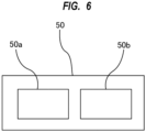
- This arithmetic system 50 includes a memory 50a that stores programs therein, and a processor 50b configured to execute arithmetic operations according to instructions included in the programs.
- the arithmetic system 50 is composed of at least one computer.
- the memory 50a includes a main memory, such as a random access memory (RAM), and an auxiliary memory, such as a hard disk drive (HDD) or a solid state drive (SSD).
- Examples of the processor 50b include a CPU (central processing unit) and a GPU (graphic processing unit).
- the specific configuration of the arithmetic system 50 is not limited to these examples.
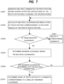
- FIG. 7 is a flowchart illustrating an embodiment of the method of determining the shape of the Roots rotor.
- the arithmetic system 50 generates multiple candidates for a Roots rotor each having a shape that satisfies specifications of the Roots rotor while changing the specifications.
- the specifications of the Roots rotor include at least one of a distance between centers of a pair of Roots rotors, a pressure angle of involute side surface 31 of Roots rotor, a radius of Roots rotor, a clearance between Roots rotors, a radius of curvature of arcuate convex surface 34 of Roots rotor, and a radius of curvature of arcuate concave surface 36 of Roots rotor.
- the arithmetic system 50 generates multiple candidates for the Roots rotor each having a shape that satisfies the specifications while changing at least one of these factors (or conditions) that constitute the specifications. For example, the arithmetic system 50 generates multiple candidates for the Roots rotor each having a shape that satisfies the specifications while changing a pressure angle of the involute side surface 31 of the Roots rotor, a radius of curvature of the arcuate convex surface 34 of the Roots rotor, and a radius of curvature of the arcuate concave surface 36 of the Roots rotor.
- step 2 the arithmetic system 50 calculates multiple clearances between a pair of Roots rotors corresponding to rotation angles of the pair of Roots rotors having a shape of one of the multiple candidates. More specifically, the arithmetic system 50 calculates the multiple clearances between the pair of Roots rotors at predetermined intervals of rotation angle while rotating the Roots rotors having the shape of the candidate in the opposite directions in a virtual space.
- FIG. 8 is a graph showing a change in the clearance between the Roots rotors when the Roots rotors of a certain candidate make one rotation.
- a vertical axis represents the clearance between the Roots rotors
- a horizontal axis represents the rotation angle of the Roots rotors.
- the arithmetic system 50 calculates the clearance between the Roots rotors at each rotation angle. Therefore, the multiple clearances corresponding to the multiple rotation angles are obtained.
- the arithmetic system 50 determines a maximum clearance among the multiple clearances obtained. In the example of FIG. 8 , the maximum clearance is a peak value of the graph. If the maximum clearance is too large, the pumping performance of the vacuum pump 1 may be lowered.
- the clearance between the Roots rotors calculated at a certain rotation angle may have a negative value.
- a negative clearance means that the Roots rotors are in contact.
- the rotation of the Roots rotors is inhibited. Therefore, in step 3, the arithmetic system 50 determines whether there is a negative clearance among the multiple clearances that have been calculated in the step 2.
- step 4 if there is a negative clearance, the arithmetic system 50 deletes the candidate with the negative clearance from the multiple candidates generated in the step 1.
- step 5 the arithmetic system 50 determines a maximum clearance among the multiple clearances calculated for the candidates.
- step 6 the arithmetic system 50 repeats the calculation of the multiple clearances and the determination of the maximum clearance for the multiple candidates, and determines multiple maximum clearances corresponding to the multiple candidates. More specifically, the computing system 50 repeats the steps 2 to 5.
- step 7 the arithmetic system 50 determines a shape of the Roots rotor of a candidate corresponding to a smallest maximum clearance among the multiple maximum clearances determined in the step 6.
- the arithmetic system 50 may calculate additional clearances by performing interpolation for the calculated multiple clearances along the rotation angle. Specifically, the arithmetic system 50 may interpolate additional clearances corresponding to additional rotation angles into the multiple clearances.
- An example of interpolation is spline interpolation.
- the maximum clearance is determined from among the multiple clearances calculated in the step 2 and the additional clearances.
- the interpolation of clearances may be performed only in a predetermined rotation angle range.
- the interpolation of clearances may be performed in a rotation angle range in which the arcuate convex surface 34 and the arcuate concave surface 36 face each other, as shown in FIG.4 .
- the interpolation of clearances may be performed in a rotation angle range that includes the rotation angle at which the minimum clearance G1 is formed between the arcuate convex surface 34 and the arcuate concave surface 36 (i.e., a rotation angle of a bottom point between the two peak points in FIG. 8 ).
- Roots rotors 8 and 9 of the embodiments described above are two-lobe Roots rotors each having two protrusions
- the present invention is not limited to the above embodiments.
- the present invention can be applied to three-lobe Roots rotor having three protrusions and multi-lobe Roots rotor having four or more protrusions.
- the embodiments of the method of determining the shape of the Roots rotor described with reference to FIGS. 6 to 8 can be applied to the three-lobe Roots rotor shown in FIG. 9 and to multi-lobe Roots rotor having four or more protrusions.
Landscapes
- Engineering & Computer Science (AREA)
- General Engineering & Computer Science (AREA)
- Mechanical Engineering (AREA)
- Physics & Mathematics (AREA)
- General Physics & Mathematics (AREA)
- Theoretical Computer Science (AREA)
- Geometry (AREA)
- Mathematical Optimization (AREA)
- Pure & Applied Mathematics (AREA)
- Mathematical Analysis (AREA)
- Data Mining & Analysis (AREA)
- Mathematical Physics (AREA)
- Computational Mathematics (AREA)
- Computer Hardware Design (AREA)
- Evolutionary Computation (AREA)
- Algebra (AREA)
- Databases & Information Systems (AREA)
- Software Systems (AREA)
- Applications Or Details Of Rotary Compressors (AREA)
- Rotary Pumps (AREA)
Applications Claiming Priority (2)
| Application Number | Priority Date | Filing Date | Title |
|---|---|---|---|
| JP2023017363A JP2024112393A (ja) | 2023-02-08 | 2023-02-08 | 真空ポンプおよびルーツロータの形状を決定する方法 |
| EP24155938.4A EP4424974A3 (de) | 2023-02-08 | 2024-02-06 | Vakuumpumpe und verfahren zur bestimmung der form eines roots-rotors |
Related Parent Applications (1)
| Application Number | Title | Priority Date | Filing Date |
|---|---|---|---|
| EP24155938.4A Division EP4424974A3 (de) | 2023-02-08 | 2024-02-06 | Vakuumpumpe und verfahren zur bestimmung der form eines roots-rotors |
Publications (2)
| Publication Number | Publication Date |
|---|---|
| EP4534846A2 true EP4534846A2 (de) | 2025-04-09 |
| EP4534846A3 EP4534846A3 (de) | 2025-07-02 |
Family
ID=89853490
Family Applications (2)
| Application Number | Title | Priority Date | Filing Date |
|---|---|---|---|
| EP25159220.0A Pending EP4534846A3 (de) | 2023-02-08 | 2024-02-06 | Vakuumpumpe und verfahren zur bestimmung der form eines roots-rotors |
| EP24155938.4A Pending EP4424974A3 (de) | 2023-02-08 | 2024-02-06 | Vakuumpumpe und verfahren zur bestimmung der form eines roots-rotors |
Family Applications After (1)
| Application Number | Title | Priority Date | Filing Date |
|---|---|---|---|
| EP24155938.4A Pending EP4424974A3 (de) | 2023-02-08 | 2024-02-06 | Vakuumpumpe und verfahren zur bestimmung der form eines roots-rotors |
Country Status (5)
| Country | Link |
|---|---|
| EP (2) | EP4534846A3 (de) |
| JP (1) | JP2024112393A (de) |
| KR (1) | KR20240124210A (de) |
| CN (1) | CN118462579A (de) |
| TW (1) | TW202438768A (de) |
Citations (1)
| Publication number | Priority date | Publication date | Assignee | Title |
|---|---|---|---|---|
| JPS6477782A (en) | 1987-09-19 | 1989-03-23 | Ebara Corp | Rotary machine of roots type |
Family Cites Families (5)
| Publication number | Priority date | Publication date | Assignee | Title |
|---|---|---|---|---|
| DE59005764D1 (de) * | 1990-08-27 | 1994-06-23 | Leybold Ag | Rotor für eine Wälzkolbenvakuumpumpe. |
| JP3254457B2 (ja) * | 1992-09-18 | 2002-02-04 | 株式会社日立製作所 | 無給油式スクリュー圧縮機のロータ形成方法およびそのロータを用いた無給油式スクリュー圧縮機 |
| CN203641003U (zh) * | 2013-12-31 | 2014-06-11 | 大连交通大学 | 罗茨真空泵的45°节圆压力角渐开线型转子 |
| CN108138774B (zh) * | 2015-08-17 | 2021-08-06 | 伊顿智能动力有限公司 | 混合齿廓增压器转子 |
| CN108799111B (zh) * | 2018-01-09 | 2023-09-22 | 中国石油大学(华东) | 一种不对称罗茨转子 |
-
2023
- 2023-02-08 JP JP2023017363A patent/JP2024112393A/ja active Pending
-
2024
- 2024-02-02 KR KR1020240016398A patent/KR20240124210A/ko active Pending
- 2024-02-04 CN CN202410156189.7A patent/CN118462579A/zh active Pending
- 2024-02-05 TW TW113104505A patent/TW202438768A/zh unknown
- 2024-02-06 EP EP25159220.0A patent/EP4534846A3/de active Pending
- 2024-02-06 EP EP24155938.4A patent/EP4424974A3/de active Pending
Patent Citations (1)
| Publication number | Priority date | Publication date | Assignee | Title |
|---|---|---|---|---|
| JPS6477782A (en) | 1987-09-19 | 1989-03-23 | Ebara Corp | Rotary machine of roots type |
Also Published As
| Publication number | Publication date |
|---|---|
| JP2024112393A (ja) | 2024-08-21 |
| KR20240124210A (ko) | 2024-08-16 |
| EP4424974A2 (de) | 2024-09-04 |
| CN118462579A (zh) | 2024-08-09 |
| EP4534846A3 (de) | 2025-07-02 |
| TW202438768A (zh) | 2024-10-01 |
| EP4424974A3 (de) | 2024-11-27 |
Similar Documents
| Publication | Publication Date | Title |
|---|---|---|
| JP6622527B2 (ja) | スクロール流体機械 | |
| TWI479078B (zh) | 多段式乾式幫浦 | |
| Hsieh et al. | Study on the tooth profile for the screw claw-type pump | |
| JPH0874765A (ja) | 無段圧縮形スクリュー式真空ポンプ | |
| JP6545787B2 (ja) | スクリューマシンの圧縮ブロック用のロータ対 | |
| JP2000161285A (ja) | ターボ分子ポンプ及び真空装置 | |
| JP2619468B2 (ja) | 無給油式スクリュー流体機械 | |
| Tien et al. | A novel design of the Roots blower | |
| CN114856997A (zh) | 螺杆泵和螺杆转子 | |
| EP4534846A2 (de) | Vakuumpumpe und verfahren zur bestimmung der form eines roots-rotors | |
| JP3074845B2 (ja) | 流体回転装置 | |
| KR930010240B1 (ko) | 스크류 유체기계 | |
| EP4682381A1 (de) | Vakuumpumpe | |
| JP7132909B2 (ja) | スクリュー式真空ポンプ | |
| EP4417787A1 (de) | Wälzkolbenvakuumpumpe | |
| JPH05202855A (ja) | 流体回転装置 | |
| JPH0932766A (ja) | スクリュ−流体機械及びねじ歯車 | |
| JPH11106343A (ja) | 容積形ポンプ | |
| JP2007162704A (ja) | スクリュー流体機械及びねじ歯車 | |
| JP2024112393A5 (de) | ||
| JP2004293377A (ja) | 多段式ドライポンプ | |
| EP1780417A1 (de) | Schraubenvakuumpumpe | |
| US8075288B2 (en) | Screw pump and pumping arrangement | |
| KR101150971B1 (ko) | 스크루 로터 타입 진공 펌프 | |
| CN116753167B (zh) | 转子及真空泵 |
Legal Events
| Date | Code | Title | Description |
|---|---|---|---|
| PUAI | Public reference made under article 153(3) epc to a published international application that has entered the european phase |
Free format text: ORIGINAL CODE: 0009012 |
|
| STAA | Information on the status of an ep patent application or granted ep patent |
Free format text: STATUS: REQUEST FOR EXAMINATION WAS MADE |
|
| 17P | Request for examination filed |
Effective date: 20250220 |
|
| AC | Divisional application: reference to earlier application |
Ref document number: 4424974 Country of ref document: EP Kind code of ref document: P |
|
| AK | Designated contracting states |
Kind code of ref document: A2 Designated state(s): AL AT BE BG CH CY CZ DE DK EE ES FI FR GB GR HR HU IE IS IT LI LT LU LV MC ME MK MT NL NO PL PT RO RS SE SI SK SM TR |
|
| REG | Reference to a national code |
Ref country code: DE Ref legal event code: R079 Free format text: PREVIOUS MAIN CLASS: F04C0025020000 Ipc: F01C0021080000 |
|
| PUAL | Search report despatched |
Free format text: ORIGINAL CODE: 0009013 |
|
| AK | Designated contracting states |
Kind code of ref document: A3 Designated state(s): AL AT BE BG CH CY CZ DE DK EE ES FI FR GB GR HR HU IE IS IT LI LT LU LV MC ME MK MT NL NO PL PT RO RS SE SI SK SM TR |
|
| RIC1 | Information provided on ipc code assigned before grant |
Ipc: F04C 25/02 20060101ALI20250526BHEP Ipc: F04C 18/12 20060101ALI20250526BHEP Ipc: F04C 18/08 20060101ALI20250526BHEP Ipc: F01C 21/08 20060101AFI20250526BHEP |
|
| GRAP | Despatch of communication of intention to grant a patent |
Free format text: ORIGINAL CODE: EPIDOSNIGR1 |
|
| STAA | Information on the status of an ep patent application or granted ep patent |
Free format text: STATUS: GRANT OF PATENT IS INTENDED |
|
| RIC1 | Information provided on ipc code assigned before grant |
Ipc: F01C 21/08 20060101AFI20260213BHEP Ipc: F04C 18/08 20060101ALI20260213BHEP Ipc: F04C 18/12 20060101ALI20260213BHEP Ipc: F04C 25/02 20060101ALI20260213BHEP |
|
| INTG | Intention to grant announced |
Effective date: 20260312 |