EP4534026A2 - Dispositif à catheter - Google Patents
Dispositif à catheter Download PDFInfo
- Publication number
- EP4534026A2 EP4534026A2 EP25158473.6A EP25158473A EP4534026A2 EP 4534026 A2 EP4534026 A2 EP 4534026A2 EP 25158473 A EP25158473 A EP 25158473A EP 4534026 A2 EP4534026 A2 EP 4534026A2
- Authority
- EP
- European Patent Office
- Prior art keywords
- rotor
- pump
- catheter device
- distal
- drive shaft
- Prior art date
- Legal status (The legal status is an assumption and is not a legal conclusion. Google has not performed a legal analysis and makes no representation as to the accuracy of the status listed.)
- Pending
Links
Images


Classifications
-
- A—HUMAN NECESSITIES
- A61—MEDICAL OR VETERINARY SCIENCE; HYGIENE
- A61M—DEVICES FOR INTRODUCING MEDIA INTO, OR ONTO, THE BODY; DEVICES FOR TRANSDUCING BODY MEDIA OR FOR TAKING MEDIA FROM THE BODY; DEVICES FOR PRODUCING OR ENDING SLEEP OR STUPOR
- A61M60/00—Blood pumps; Devices for mechanical circulatory actuation; Balloon pumps for circulatory assistance
- A61M60/40—Details relating to driving
- A61M60/403—Details relating to driving for non-positive displacement blood pumps
- A61M60/419—Details relating to driving for non-positive displacement blood pumps the force acting on the blood contacting member being permanent magnetic, e.g. from a rotating magnetic coupling between driving and driven magnets
-
- A—HUMAN NECESSITIES
- A61—MEDICAL OR VETERINARY SCIENCE; HYGIENE
- A61M—DEVICES FOR INTRODUCING MEDIA INTO, OR ONTO, THE BODY; DEVICES FOR TRANSDUCING BODY MEDIA OR FOR TAKING MEDIA FROM THE BODY; DEVICES FOR PRODUCING OR ENDING SLEEP OR STUPOR
- A61M60/00—Blood pumps; Devices for mechanical circulatory actuation; Balloon pumps for circulatory assistance
- A61M60/10—Location thereof with respect to the patient's body
- A61M60/122—Implantable pumps or pumping devices, i.e. the blood being pumped inside the patient's body
- A61M60/126—Implantable pumps or pumping devices, i.e. the blood being pumped inside the patient's body implantable via, into, inside, in line, branching on, or around a blood vessel
- A61M60/13—Implantable pumps or pumping devices, i.e. the blood being pumped inside the patient's body implantable via, into, inside, in line, branching on, or around a blood vessel by means of a catheter allowing explantation, e.g. catheter pumps temporarily introduced via the vascular system
-
- A—HUMAN NECESSITIES
- A61—MEDICAL OR VETERINARY SCIENCE; HYGIENE
- A61M—DEVICES FOR INTRODUCING MEDIA INTO, OR ONTO, THE BODY; DEVICES FOR TRANSDUCING BODY MEDIA OR FOR TAKING MEDIA FROM THE BODY; DEVICES FOR PRODUCING OR ENDING SLEEP OR STUPOR
- A61M60/00—Blood pumps; Devices for mechanical circulatory actuation; Balloon pumps for circulatory assistance
- A61M60/20—Type thereof
- A61M60/205—Non-positive displacement blood pumps
- A61M60/216—Non-positive displacement blood pumps including a rotating member acting on the blood, e.g. impeller
- A61M60/237—Non-positive displacement blood pumps including a rotating member acting on the blood, e.g. impeller the blood flow through the rotating member having mainly axial components, e.g. axial flow pumps
-
- A—HUMAN NECESSITIES
- A61—MEDICAL OR VETERINARY SCIENCE; HYGIENE
- A61M—DEVICES FOR INTRODUCING MEDIA INTO, OR ONTO, THE BODY; DEVICES FOR TRANSDUCING BODY MEDIA OR FOR TAKING MEDIA FROM THE BODY; DEVICES FOR PRODUCING OR ENDING SLEEP OR STUPOR
- A61M60/00—Blood pumps; Devices for mechanical circulatory actuation; Balloon pumps for circulatory assistance
- A61M60/80—Constructional details other than related to driving
- A61M60/802—Constructional details other than related to driving of non-positive displacement blood pumps
- A61M60/804—Impellers
- A61M60/806—Vanes or blades
- A61M60/808—Vanes or blades specially adapted for deformable impellers, e.g. expandable impellers
-
- A—HUMAN NECESSITIES
- A61—MEDICAL OR VETERINARY SCIENCE; HYGIENE
- A61M—DEVICES FOR INTRODUCING MEDIA INTO, OR ONTO, THE BODY; DEVICES FOR TRANSDUCING BODY MEDIA OR FOR TAKING MEDIA FROM THE BODY; DEVICES FOR PRODUCING OR ENDING SLEEP OR STUPOR
- A61M60/00—Blood pumps; Devices for mechanical circulatory actuation; Balloon pumps for circulatory assistance
- A61M60/80—Constructional details other than related to driving
- A61M60/802—Constructional details other than related to driving of non-positive displacement blood pumps
- A61M60/81—Pump housings
-
- A—HUMAN NECESSITIES
- A61—MEDICAL OR VETERINARY SCIENCE; HYGIENE
- A61M—DEVICES FOR INTRODUCING MEDIA INTO, OR ONTO, THE BODY; DEVICES FOR TRANSDUCING BODY MEDIA OR FOR TAKING MEDIA FROM THE BODY; DEVICES FOR PRODUCING OR ENDING SLEEP OR STUPOR
- A61M60/00—Blood pumps; Devices for mechanical circulatory actuation; Balloon pumps for circulatory assistance
- A61M60/80—Constructional details other than related to driving
- A61M60/802—Constructional details other than related to driving of non-positive displacement blood pumps
- A61M60/818—Bearings
- A61M60/825—Contact bearings, e.g. ball-and-cup or pivot bearings
-
- A—HUMAN NECESSITIES
- A61—MEDICAL OR VETERINARY SCIENCE; HYGIENE
- A61M—DEVICES FOR INTRODUCING MEDIA INTO, OR ONTO, THE BODY; DEVICES FOR TRANSDUCING BODY MEDIA OR FOR TAKING MEDIA FROM THE BODY; DEVICES FOR PRODUCING OR ENDING SLEEP OR STUPOR
- A61M60/00—Blood pumps; Devices for mechanical circulatory actuation; Balloon pumps for circulatory assistance
- A61M60/10—Location thereof with respect to the patient's body
- A61M60/122—Implantable pumps or pumping devices, i.e. the blood being pumped inside the patient's body
- A61M60/126—Implantable pumps or pumping devices, i.e. the blood being pumped inside the patient's body implantable via, into, inside, in line, branching on, or around a blood vessel
- A61M60/148—Implantable pumps or pumping devices, i.e. the blood being pumped inside the patient's body implantable via, into, inside, in line, branching on, or around a blood vessel in line with a blood vessel using resection or like techniques, e.g. permanent endovascular heart assist devices
-
- A—HUMAN NECESSITIES
- A61—MEDICAL OR VETERINARY SCIENCE; HYGIENE
- A61M—DEVICES FOR INTRODUCING MEDIA INTO, OR ONTO, THE BODY; DEVICES FOR TRANSDUCING BODY MEDIA OR FOR TAKING MEDIA FROM THE BODY; DEVICES FOR PRODUCING OR ENDING SLEEP OR STUPOR
- A61M60/00—Blood pumps; Devices for mechanical circulatory actuation; Balloon pumps for circulatory assistance
- A61M60/40—Details relating to driving
- A61M60/403—Details relating to driving for non-positive displacement blood pumps
- A61M60/408—Details relating to driving for non-positive displacement blood pumps the force acting on the blood contacting member being mechanical, e.g. transmitted by a shaft or cable
- A61M60/411—Details relating to driving for non-positive displacement blood pumps the force acting on the blood contacting member being mechanical, e.g. transmitted by a shaft or cable generated by an electromotor
- A61M60/414—Details relating to driving for non-positive displacement blood pumps the force acting on the blood contacting member being mechanical, e.g. transmitted by a shaft or cable generated by an electromotor transmitted by a rotating cable, e.g. for blood pumps mounted on a catheter
-
- A—HUMAN NECESSITIES
- A61—MEDICAL OR VETERINARY SCIENCE; HYGIENE
- A61M—DEVICES FOR INTRODUCING MEDIA INTO, OR ONTO, THE BODY; DEVICES FOR TRANSDUCING BODY MEDIA OR FOR TAKING MEDIA FROM THE BODY; DEVICES FOR PRODUCING OR ENDING SLEEP OR STUPOR
- A61M60/00—Blood pumps; Devices for mechanical circulatory actuation; Balloon pumps for circulatory assistance
- A61M60/80—Constructional details other than related to driving
- A61M60/802—Constructional details other than related to driving of non-positive displacement blood pumps
- A61M60/827—Sealings between moving parts
- A61M60/829—Sealings between moving parts having a purge fluid supply
Definitions
- the invention relates to a catheter device, in particular a catheter device with an elongated drive shaft.
- a well-known transfemoral implantable micro-axial pump the "Hemopump TM” from Medtronic Inc., USA, has been shown, after experimental and preliminary clinical trials, to be a promising concept that can provide sufficient left ventricular relief.
- the pump's intake port is placed retrogradely over the aortic valve in the left ventricle.
- the pump rotor is located at the end of a cannula in the superior descending aorta and is driven by an external motor.
- the disadvantage of this system is that, due to the rotor's large diameter, transfemoral implantation is only possible surgically via a femoral artery graft and, if necessary, by grafting.
- the result is an axial pump that can be inserted through a patient's vascular system.
- the axial pump has a flexible, compressible tube that forms the pump housing.
- a radially compressible rotor is located within the tube.
- the rotor's drive shaft runs through a catheter.
- the catheter, together with the tube and rotor, can be pulled into a cover tube.
- the radial compressibility of the components allows for the realization of a puncture diameter that is acceptable for percutaneous implantation using the Seldinger technique.
- a relatively large pump diameter of 10 to 14 mm can be provided. This reduces the rotor speed and thus the mechanical stress on the components.
- the pump has a drive part and a pump part, which have such a small diameter that they can be pushed through a blood vessel.
- a flexible cannula is connected to the pump part.
- the cannula can be expanded to a diameter that is larger than that of the drive part or the pump part.
- the cannula is constricted, in which it has a small diameter. In the blood vessel, it is expanded so that it offers less flow resistance for the blood to be pumped.
- a catheter with an integrated blood pump is described.
- a flexible rim extends over a tubular section of the catheter and contacts the walls of the aorta, ensuring that all blood within the aorta flows through the pump.
- the flexible, expandable rim also distances the pump from the aortic valve.
- the present invention is based on the object of creating a catheter device with a drive shaft extending almost over the entire catheter device, which can be reliably driven at high speed.
- the magnetic ring bearing or rather the magnetic connection between the two magnet units, limits the contribution of the transmittable torque. As soon as the adjustable torque is exceeded, the two magnet units separate.
- the catheter device comprises a tubular catheter shaft that surrounds the drive shaft and extends from the proximal end region to the distal end region of the catheter device.
- the catheter shaft is connected to the coupling housing at its proximal end in a fluid-tight manner.
- a flushing hole in the coupling housing allows the introduction of a flushing medium to lubricate the drive shaft and the output-side coupling elements. This prevents blood from penetrating the area between the drive shaft and the catheter shaft and impairing the rotation of the drive shaft.
- a coupling element on the output side supporting the distal magnet unit is supported by a plain bearing. This allows the distance between the two magnet units to be precisely determined.
- the maximum torque that can be transmitted by the magnetic coupling is set both by the distance between the two magnetic units determined by the plain bearing and by the force with which the coupling element is subjected in the axial direction by the magnetic ring bearing.
- the diameter of the drive shaft can range from 0.3 mm to 1 mm, and is preferably approximately 0.4 mm to 0.6 mm. The smaller the diameter of the drive shaft, the higher the rotational speed at which the drive shaft is driven by the motor can be.
- the element rotating by means of the drive shaft can be a rotor, a milling tool or another tool.
- Such a rotor is preferably designed to be self-expanding. It can be provided with a pump housing that, like the rotor, can be compressed to a small diameter. According to a preferred embodiment, the rotor and the pump housing are made of a shape-memory material.
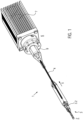
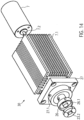
- Figure 1 shows a catheter device 1.
- the catheter device 1 according to the invention represents a pump.
- the catheter device 1 has a pump head 3 at a distal end 2.
- the pump head 3 has a rotor 3.2 for conveying a medium in the conveying direction 5, which is connected to a drive shaft 4.
- the conveying direction 5 is directed from the distal end 2 to a proximal end 6.
- a motor 7 is arranged at the proximal end 6, which is spaced from the pump head 3.
- the drive shaft 4 is surrounded by a catheter shaft 8 and is non-positively connected to the motor 7 by means of a coupling 9.
- the pump head 3 will be explained in more detail below.
- the pump head 3 comprises a shaft cap 10 at the distal end, the rotor 3.2 arranged on the drive shaft 4, a pump housing 3.1, and an outflow hose 18.
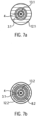
- the butt cap 10 is formed from a ball 10.1 with an attached cylindrical section 10.2.
- the butt cap 10 is made of stainless steel, for example ( Fig.2 , Fig.3
- the butt plate 10 could also be made of polyethylene PE, polypropylene PP, polyetheretherketone PEEK, polyvinyl chloride PVC, Teflon PTFE, acrylic glass, epoxy resin, polyurethane PU, carbon fiber, coated materials, composite materials, PEBAX, or a polyether block amide. In principle, all hemocompatible materials are suitable, since only low mechanical stress occurs on this component.
- the diameter of the ball 10.1 is approximately 3.2 mm.
- the cylindrical section 10.2 is approximately 5.5 mm long and has a diameter of approximately 2.2 mm.
- the total length of the butt plate is approximately 7.0 mm.
- the cylindrical section 10.2 has, at its distal end, in the connection area to the ball 10.1, a through-bore 10.3 arranged transversely to the conveying direction 5. Furthermore, the cylinder 10.2 has an axial bore 10.4 extending from the proximal end of the cylindrical section 10.2 to the ball 10.1, so that a communicating passage is formed from the through-bore 10.3 to the proximal end of the shaft cap 10. A step 10.5 is formed in the area of the axial bore 10.4, so that the axial bore is widened toward the proximal end.
- the through hole 10.3 prevents the formation of a blind hole in the shaft cap and also allows the attachment of a thread which is helpful when compressing the pump head 3.
- the tip of the shaft cap 10 is an atraumatic ball to protect the heart muscle (endocardium).
- the shaft cap 10 can be used to support the pump head 3 against the heart wall.
- a tubular or hose-shaped distal catheter shaft piece 8.1 is inserted from the proximal end into the shaft cap 10 up to the step.
- the distal catheter shaft piece 8.1 is precisely received in the axial bore 10.4 and is fixed there ( Fig. 4 ).
- the distal catheter shaft piece 8.1 is made of polyurethane or another suitable material, in particular an elastic plastic material (e.g., PE, PVC, Teflon, elastomer).
- the distal end of the distal catheter shaft piece 8.1 is connected to the shaft cap 10.
- the connection can be formed as an adhesive connection using, for example, cyanoacrylate adhesive. or it is carried out as a welded, clamped, or shrink-fit connection.
- the distal catheter shaft piece 8.1 forms a straight, yet slightly flexible connection between the shaft cap 10 and the pump housing 3.1. This straight connection ensures coaxiality of all components arranged within it (drive shaft, shaft guard, housing, connecting bushing).
- the distal catheter shaft piece 8.1 in conjunction with the shaft cap 10, serves as a positioning aid for the pump head 3 when it is inserted into a vessel or the heart.
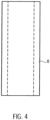
- the catheter shaft piece 8.1 in the present embodiment has a length of approximately 25 mm, an outer diameter of approximately 1.9 mm and an inner diameter of approximately 1.3 mm.
- the distal connecting bushing 12.1 has a length of approximately 5 mm and an outer diameter of approximately 2.2 mm.
- the diameter in the distal region is approximately 2 mm and in the proximal region approximately 1.5 mm. The shorter the connecting bushing, the less stiffening it provides.
- the distal and an analogously designed proximal connecting bushing 12.1, 12.2 are made, for example, of stainless steel, copper, brass, titanium or another suitable metal, of polyethylene (PE), polypropylene (PP), Teflon (PTFE), PEBAX, a polyether block amide, or another suitable material.
- the expandable or compressible pump housing 3.1 is a tubular lattice structure 3.1.6 made of Nitinol or another suitable shape memory alloy or another shape memory material, e.g., plastic, iron alloy, copper alloy.
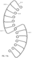
- the pump housing 3.1 is divided into five sections from distal to proximal ( Fig. 8 ).
- the first distal section is a tubular distal connecting section 3.1.1.
- a second section is a suction section 3.1.2 which widens conically in the conveying direction 5.
- a pump section 3.1.3 is connected to the suction section 3.1.2.
- the tubular pump section 3.1.3 accommodates the rotor 3.2.
- the inner diameter of the pump section 3.1.3 in the expanded state is approximately 6.15 mm.
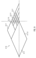
- large diamonds 3.1.7.2 are provided, which have approximately four times the edge length of the small diamonds 3.1.7.1.
- the large diamonds 3.1.7.2 are combined into smaller diamonds.
- medium-sized diamonds 3.1.7.3 are provided, which have approximately twice the edge length of the small diamonds 3.1.7.1 ( Fig. 9 ).
- the design of the openings (3.1.7) and the number of multiplications can be arbitrary.
- the width of the lattice struts is increased. This keeps the strength of the lattice struts roughly the same, or even increases it toward the larger diamonds.
- the grid structure 3.1.6 of the pump housing 3.1 is covered with a PU covering 3.1.8 in the pump section 3.1.3, whereby the grid openings are sealed liquid-tight.
- a covering other than PU can also be used, such as PE, PP, silicone or parylene, as long as it meets the mechanical and geometric requirements.
- the performance parameters of the pump including blood damage, can be specifically controlled.
- the polygonal structure and the special design of the PU covering result in an almost round cross-sectional shape for the pump housing 3.1. In conjunction with the round rotor 3.2, this results in very small gaps between the rotor 3.2 and the pump housing 3.1. This leads to comparatively low Blood damage, low leakage currents, and good efficiency.
- the 3.1.6 lattice structure results in very good radial and axial stability, as well as excellent axial compressibility and expandability.
- the special structure allows for easy adjustment of length and diameter to meet performance requirements.
- the proximal connecting section 3.1.5 of the pump housing 3.1 is received in the proximal connecting socket 12.2 and connected to it.
- a tubular proximal catheter shaft piece 8.2 is received in the proximal connecting socket 12.2 and connected to it ( Fig. 7a, Fig. 7b ).
- the same connection types described above can be used.
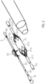
- a distal shaft protector 13.1 and a proximal shaft protector 13.2 are arranged in the axial direction ( Fig. 6 ).
- the distal and proximal shaft protection 13.1, 13.2 are designed as a tube made of PU or one of the other materials listed above.
- the distal shaft guard 13.1 extends in the pumping direction 5 from just before the distal connecting bushing 12.1 to the distal end of the pump section 3.1.3 of the pump housing 3.1, i.e., to the rotor 3.2.
- the proximal shaft guard 13.2 extends from the proximal end of the rotor 3.2 to just behind the proximal end of the proximal connecting bushing 12.1.
- the distal and proximal shaft protectors 13.1, 13.2 are connected to the distal and proximal connecting sleeves 12.1, 12.2 and the distal and proximal catheter shaft pieces 8.1, 8.2 in the two areas in which they are arranged within these.
- the connecting bushings 12.1, 12.2 ensure the axial centering of the drive shaft 4, particularly in the pump housing 3.1.
- the proximal shaft protection 13.1 ( Fig. 2 , Fig. 6 ) separates the proximal section 4.3 of the drive shaft 4 from the pump medium to protect against blood damage caused by the rotational movement of the drive shaft 4 and the adhesion of blood components to the drive shaft 4. This prevents the buildup of shear forces. There is no direct interaction between the drive shaft 4 and the blood due to the very small gap, and only minimal blood transport through this gap is possible.
- the distal and proximal shaft guards 13.1, 13.2 center and support the drive shaft 4 during operation and during the compression and expansion process.
- the drive shaft 4 is preferably formed from several, in particular six, wires (not shown), which are wound left- or right-hand around a core (not shown).
- the outer diameter of the drive shaft 4 is approximately 0.48 mm.
- the drive shaft 4 can also have a different number of cores and wires and a smaller or larger diameter.
- the diameter of the drive shaft can range from 0.3 mm to 1 mm and is preferably approximately 0.4 mm to 0.6 mm.
- the smaller the diameter of the drive shaft the higher the rotational speed can be, because the smaller the diameter, the lower the speed at which the circumference of the drive shaft moves relative to its surroundings. A high circumferential speed is problematic if the drive shaft comes into contact with the environment.
- the catheter device is designed for speeds of more than 20,000 rpm and up to 40,000 rpm. Therefore, the diameter of the drive shaft 4 is designed to be as small as possible, but thick enough to still have sufficient strength.
- the drive shaft 4 extends from the distal end of the distal shaft guard 13.1 in the conveying direction 5 behind the distal connecting bush 12.1 to the coupling 9.
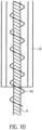
- the spiral-shaped, expandable rotor 3.2 is arranged in a rotationally fixed manner on the drive shaft 4.
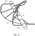
- the rotor 3.2 is a two-bladed, comb-shaped frame structure 3.2.1 made of Nitinol or another shape memory material, e.g., plastic (see above), which is coated with a PU skin or surrounded by it in a liquid-tight manner ( Fig. 11a ). This means that the covering, in the form of a PU skin, is stretched between the comb-shaped frame structure.
- the construction of the rotor 3.2 as a coated frame structure 3.2.1 made of Nitinol makes it possible to expand or compress the rotor 3.2.
- the PU skin is highly elastic, so it is not damaged during compression.
- the frame structure 3.2.1 has a circumferential, helical or spiral outer boundary frame 3.2.2 with several rotor struts 3.2.3 running radially inwards with the boundary frame 3.2.2 ( Fig. 12 ). Rings 3.2.4 are formed at the free ends of the rotor struts 3.2.3.
- the drive shaft 4 extends through the rings 3.2.4 of the rotor struts 3.2.3.
- the rotor 3.2 can also be made in one piece ( Fig. 11b ) or have several frame structures ( Fig. 11a ). Each frame structure forms a rotor blade.
- FIG. 11b and 12 A frame structure 3.2.1 for a rotor 3.2 is shown, which forms two rotor blades. If required, several rotor blades and accordingly Several frame structures 3.2.1 may be arranged on a rotor 3.2.
- the frame structure may also have any other suitable shape.
- the distance between two adjacent rings 3.2.4 is smaller than the corresponding section of the spiral-shaped boundary frame 3.2.2.
- the length of the spacer sleeves 16 can thus determine the pitch of the rotor 3.2. It can vary within a rotor 3.2.
- the pitch of rotor 3.2 is determined by the length or number of spacer sleeves 16 in relation to the dimensions of the circumferential, spiral-shaped outer boundary frame 3.2.2 between two rotor struts 3.2.3.
- the length of the spacer sleeves 16 can be uniform for all positions, but it can also be varied symmetrically or asymmetrically for each position. This complete design freedom allows for a very flexible design of rotor 3.2. This flexible design makes it possible to generate different conveying or pumping characteristics of rotor 3.2.
- the Rotor 3.2 exhibits high dimensional stability with flexible design options and minimal material usage (e.g., a thin frame structure). Maximum rigidity and stability are achieved. Nevertheless, the combination of the frame structure and the covering, which further supports the properties of the frame structure through stabilization, allows for very strong compression. This results in the rotor's excellent compressibility and expandability. The excellent surface formation of the PU skin on the lattice structure allows for a very good adaptation of the housing structure to the rotor structure.
- the rotor 3.2 In the compressed state, the rotor 3.2 has approximately the inner diameter of the compressed pump housing 3.1.
- the outer diameter of the compressed pump housing is approximately between 2 mm and 4 mm, and preferably approximately 3.3 mm.
- the spiral-shaped outer boundary frame 3.2.2 of the rotor 3.2 is slightly spaced from the inner surface of the pump housing 3.1.
- the distance between the outer boundary frame 3.2.2 and the inner surface of the pump housing 3.1 is approximately between 0.01 mm and 0.5 mm. The smaller the distance between the frame structure 3.2.1 and the inner surface of the pump housing 3.1, the higher the pumping capacity of the rotor 3.2.
- the distal spacer sleeve 16 of the rotor 3.2 contacts the bearing disk 15 in the manner of a plain bearing. In this way, a distal rotor bearing 17 is formed ( Fig.6 ).
- the drive shaft 4 is accommodated in the through hole of the bearing disc 15 with almost no play. Only small clearances (not shown) remain due to the design of the drive shaft 4.
- the drive shaft 4 is similarly received by a proximal connecting bushing 12.2 on the proximal end spacer sleeve 16 of the rotor 3.2.
- a tubular elastic discharge hose 18 is arranged ( Fig. 1 , Fig. 13 ).
- the outflow tube 18 is made of PU.
- the outflow tube 18 has a length of approximately 70 mm, a diameter of approximately 10 mm, and a wall thickness of approximately 0.01 mm to 0.1 mm, and preferably approximately 0.03 mm.
- the two ends of the outflow tube 18 are tapered, with a cylindrical section arranged at the proximal conical end of the outflow tube.
- the distal, tapered end of the outflow tube 18 forms a tight seal with the PU covering of the pump section 3.1.3 of the pump housing 3.1.
- the cylindrical proximal section is firmly connected to the proximal catheter shaft piece 8.2. Both are connected to each other in a fluid-tight manner using dissolved PU.
- outlet openings 18.1 are arranged radially around the circumference.
- the outlet openings 18.1 can, for example, be oval in the flow direction 5.
- the outlet openings can also be round, crescent-shaped, or have any desired geometry to generate other outlet flows.
- the outlet openings 18.1 swirl the blood exiting the aortic bulb. This prevents laminar flow and thus the water jet pump effect against the coronary arteries.
- the coupling 9 and the motor 7 are located at the proximal end of the catheter shaft 8.2.
- the distance between the pump head 3 and the coupling 9, or the length of the proximal catheter shaft section 8.2, can vary depending on the patient and is approximately 90 to 150 cm.
- a tubular cover tube 29 is arranged above the catheter device 1.
- the cover tube 29 is designed to surround the compressed pump head 3 and the proximal catheter shaft piece 8.2.
- the cover tube 29 holds the pump head 3 in its compressed state.
- the cover tube 29 is retracted from the fixed catheter device 1 until the pump head 3 is exposed.
- the pump housing 3.1 and rotor 3.2 expand radially outward due to the spring force of the elastic material. This means that the lattice structure 3.1.6 of the pump housing 3.1 and the frame structure 3.2.1 of the rotor 3.2 expand until they reach their predetermined diameter. It may also be possible to utilize the temperature effects of the memory material to assist in the expansion process.
- the cover tube 29 is advanced to the shaft cap 10, whereby the rotor 3.2 and the pump housing 3.1 are compressed and drawn into the cover tube, after which the cover tube is extracted through the puncture site.
- the clutch 9 is a magnetic clutch ( Fig. 14 , Fig. 15 ).
- the coupling 9 has a coupling housing 19 with a distal magnet unit 23.1.
- the coupling housing 19 is connected to the proximal catheter shaft piece 8.2, which forms a continuous cavity.
- the coupling housing 19 hermetically separates the proximal catheter shaft piece 8.2 from a motor assembly 30.
- the motor assembly 30 has a proximal magnet unit 23.2.
- the proximal magnet unit 23.2 is frictionally connected to the motor 7.
- the distal magnet unit 23.1 is connected to the drive shaft 4 via a coupling element 22.
- the distal magnet unit 23.1 and the proximal magnet unit 23.2 are coupled to each other via magnetic forces to prevent rotation.
- the two magnet units 23.1 and 23.2 ensure a force-locking connection with contact-free rotational force transmission.
- the coupling housing 19 has, from distal to proximal, a distal cylindrical section 19.1, a conically widening section 19.2, a second cylindrical section 19.3, and a proximal cylindrical section 19.4.
- the coupling housing is made, for example, of polymethylacrylate (PMMA) or another injection-moldable or machineable material.
- a through-bore is formed in the distal cylindrical section 19.1, centrally located in the axial direction.
- the through-bore extends through the entire coupling housing 19.
- the through-bore narrows in three stages from a first catheter shaft receiving section 19.5 to a second guide coil receiving section 19.6 and to a third drive shaft passage section 19.7.
- the proximal end of the proximal catheter shaft is arranged in the catheter shaft receiving section 19.5 of the coupling housing 19 and is firmly connected thereto.
- the guide coil 14 is received in the guide coil receiving section 19.6.
- the bearing section 19.9 has a diameter of approximately 10 mm.
- the bore of the distal coupling section 19.10 merges into a larger proximal coupling section 19.11.
- Eight M 1.6 threaded bores 19.13 are radially symmetrically formed in the shoulder 19.12 formed between the distal and proximal coupling sections 19.10 and 19.11.
- three L-shaped milled recesses 19.14 are arranged around the circumference.
- the distal coupling section 19.10 has a diameter of approximately 22 mm.
- the flushing bore 19.15 has a diameter of approximately 6.5 mm and the proximal coupling section 19.11 has a diameter of approximately 30 mm.
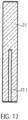
- the proximal end of the drive shaft 4 is connected to a cuboidal square rod 21 in a rotationally, tensile and compressively resistant manner (force-locking) ( Fig.17 ).
- the square rod 21 has a recess 21.1 for receiving the proximal end of the drive shaft 4.
- the drive shaft 4 is fixed in the recess.
- the square rod 21 is made of brass, for example, which has good lubricating properties.
- Other suitable materials include all materials that can be extruded or machined, such as PE, PP, PTFE, gold, silver, titanium, diamond, etc.
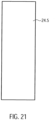
- the square bar 21 has a length of approximately 19.4 mm and a cross-section of approximately 2.88 mm x 2.88 mm.
- the square rod 21 is axially displaceably received by an axial recess 22.1 within a rotationally symmetrical coupling element 22 ( Fig. 23 ). This enables it to compensate for length differences in the axial direction ( Fig. 18 ).
- the recess 22.1 is formed by a larger, central bore and four smaller bores arranged along the circumference of the central bore.
- the bores can be formed by drilling, erosion, ultrasonic drilling, laser drilling, or water jet drilling.
- More or fewer stop edges can also be provided.
- a square bar a triangular or pentagonal bar, or a profile bar with any cross-sectional area that remains constant in the longitudinal direction of the bar, can also be provided.
- the shape of the recess 22.1 must be adapted to the cross-sectional area of the profile bar.
- a shoulder 22.4 is formed at the distal outer end or circumference of the cylindrical section 22.2 of the coupling element 22.
- a second inner ring magnet 20.2 is arranged on this shoulder 22.4.
- the shoulder 22.4 accommodates the ring magnet 20.2 such that its outer surface is flush with the outer surface of the cylindrical section 22.2.
- the ring magnet forms a magnetic ring bearing 20.3.
- the two ring magnets 20.1, 20.2 are arranged such that, for example, the north pole of the outer ring magnet is oriented distally and the south pole proximally.
- the north and south poles of the inner ring magnet are correspondingly opposite each other. Accordingly, the north and south poles of the two ring magnets can also be reversed.
- the magnetic ring bearing 20.3 centers the drive shaft 4 in the axial and radial directions. Radial centering is achieved by the magnetic attraction forces in the radial direction.
- Axial centering is achieved by generating magnetic restoring forces when the inner ring magnet 20.2 is slightly misaligned, pulling the inner ring magnet 20.2 into a position that coincides with the axial position of the outer ring magnet 20.1. However, when the misalignment is greater, repulsive forces occur between the two magnetic rings 20.1 and 20.2, forcing them apart.
- the ring magnets 20.1 and 20.2 do not touch each other, meaning no lubrication is required.
- the magnetic ring bearing also has a vibration-damping effect.
- the centric circular milling 22.5 has a diameter of approximately 16.5 mm and a depth of approximately 3 mm.
- the magnet holder 22.5 accommodates the four-segmented annular distal magnet unit 23.1.
- the annular distal magnet unit is glued into the magnet holder 22.5.
- a ball-and-socket bearing receptacle 22.7 is formed centrally in the proximal end face of the coupling element 22.
- the ball-and-socket bearing receptacle 22.7 is an approximately hemispherical recess 22.7.
- the hemispherical recess 22.7 has a diameter of approximately 0.5 to 1.3 mm.
- the square rod 21 or the cylindrical section of the coupling element 22 is received by the fourth bore section 19.8 or the bearing section 19.9 of the coupling housing 19.
- the disc-shaped section 22.3 of the Coupling element 22 is received by the distal coupling section 19.10 of the coupling housing 19.
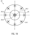
- the clutch housing 19 is hermetically separated from the motor assembly by a cover plate 24 ( Fig. 19 ).
- the clutch housing 19 is gas- and liquid-tight except for the flushing bore 19.15 in the clutch housing 22 and the spaces between the drive shaft passage section 19.7 and the drive shaft 4.
- the cover plate 24 On the distal side, the cover plate 24 has a central thickening 24.2. A through-hole 24.3 and a central hemispherical cutout 24.4 are formed in the center of the cover plate 24. A cylindrical centering pin 24.5 is fixed in the through-hole 24.3 ( Fig.21 ). On the centering pin 24.5 there is a ball head 24.6 which is accommodated in the hemispherical milling ( Fig. 15 , Fig. 20 ).
- a force is applied proximally to the distal magnet unit 23.1. These opposing forces produce a resulting force that presses the coupling element 22 against the ball head 24.6. This resulting force is adjusted so that the ball head 24.6 is securely mounted while still minimizing wear in the ball head bearing.
- the ball head 24.6 forms a ball head bearing 25 in conjunction with the distally arranged ball head bearing receptacle 22.7 of the coupling element 22.
- the ball head bearing 25 is a plain bearing.
- other plain bearings are also possible, such as a Tapered head bearings or cylindrical head bearings are possible, in which a cone or cylinder serves as the bearing body instead of a ball.
- the mount is adapted to the shape of the bearing body.
- the axial centering of the magnetic ring bearing 20.3 is achieved by positioning the inner ring magnet 20.2 not exactly centrally within the outer ring magnet 20.1 in the axial direction, but rather slightly offset proximally. This applies a distal force to the inner ring magnet 20.2.
- the ball head 24.6 can be made of ruby, aluminum oxide, or a hard plastic.
- the motor assembly comprises the proximal magnet unit 23.2, a proximal magnet holder 26, a coupling flange 27, a motor holder 7.1, with a cooling fan arranged thereon and the motor 7 ( Fig. 14 , Fig. 22 ).
- proximal magnet unit 23.2 On the proximal side of the cover plate 24, at a distance of approximately 0.5 to 8 mm and preferably approximately 1 to 2 mm, there is a proximal magnet unit 23.2 arranged axially aligned with the distal magnet unit 23.1.
- the proximal annular magnet unit 23.2 has four segments, similar to the distal magnet unit 23.1.
- the magnet holder 26 is disc-shaped and has a central circular cutout 26.1 on its distal side. Analogous to the distal magnet unit 23.1, four magnet segments are glued into the cutout 26.1 using a two-component epoxy resin adhesive or cyanoacrylate adhesive (see above).
- the four segments of the distal and proximal magnet units 23.1, 23.2 can be designed as curved bar magnets, each with a different polarity at their end regions.
- the four segments can also be designed as four quarters of a curved ring magnet.
- the segments can also be designed as short, axially aligned bar magnets arranged in a ring. More than four segments can also be provided. In the initial position, the two magnets are arranged such that a north and a south pole of the bar magnets of the two magnet units 23.1, 23.2 overlap and attract each other.
- the four segments are arranged four times with their north and south poles alternating in abutment, so that the segments of a magnet unit attract each other.
- the distal and proximal magnet units 23.1, 23.2 are arranged in such a way that complementary poles are positioned opposite each other. This attracts the two magnet units, allowing torque to be transmitted, since the magnetic forces tend to maintain this complementary pole arrangement.
- the central circular milling 26.1 has a diameter of approximately 16.5 mm and a depth of approximately 3 mm.
- the magnet holder 26 is connected to a motor shaft 7.2 of the motor 7.
- the magnet holder 26 is rotatably arranged within a correspondingly shaped recess of the coupling flange 27 of the motor holder.
- Three dowel pins 27.1 are arranged at equal distances around the circumference of the annular web of the recess.
- the coupling flange 27 is mounted on a distal end face 7.1.1 of the motor mount, maintaining axial symmetry.
- the motor mount 7.1 is a cuboid-shaped body with cooling fins 7.1.3 arranged on its side surfaces 7.1.2.
- the motor mount 7.1 has a centrally located bore 7.1.4 in the axial direction.
- the motor shaft 7.2 is guided through this bore 7.1.4.
- an axially aligned recess 7.1.5 is provided in which the motor 7 is arranged.
- the motor 7 is, for example, a standard electric motor from Faulhaber with an output of 38 W at 30,000 rpm or another suitable motor.
- a cooling fan is arranged on a side surface 7.1.2 of the cuboid motor mount 7.1.
- a cover tube 29 is arranged over the pump head 3 and a distal region of the proximal catheter shaft.
- the cover tube 29 has an inner diameter that, in the region of the pump head 3, corresponds to the outer diameter of the non-expanded pump housing.
- the outer diameter of the cover tube is approximately 3 mm.
- the ball head bearing holder 22.7 of the coupling element 22 is pressed onto the ball head 24.6 of the cover plate 24, forming the ball head bearing 25.
- the ball head bearing centers the axial run of the drive shaft 4.
- the inner ring magnet 20.1 is radially guided at a constant distance within the outer ring magnet 20.2.
- the magnetic ring bearing 20.3, in conjunction with the ball head bearing 25, centers and guides the rotationally symmetrical running of the coupling element 22 or the drive shaft 4 to prevent impacts or imbalance.
- the motor shaft 7.2 rotates at a speed of approximately 20,000 rpm to 40,000 rpm and preferably approximately 32,000 rpm to 35,000 rpm, which is transmitted to the drive shaft 4.
- the rotor 3.2 delivers a flow rate of approximately 2 l/min to 2.5 l/min at a differential pressure of 60 mm Hg.
- the drive shaft 4 twists or shortens, and the resistance at the distal magnet unit 23.1 increases.
- the magnetic fields between the proximal and distal magnet units 23.2, 23.1 do not completely overlap during operation, since the distal magnet unit 23.1 always lags slightly. If the required torque on the distal magnet unit 23.1 increases, the north and south poles of the magnet units 23.1, 23.2 no longer overlap but repel each other. As a result, the distal magnet unit 23.1 is pushed distally by the proximal magnet unit 23.2. The magnetic connection between the two magnet units 23.1, 23.2 is severed. The drive shaft 4 immediately stops.
- the inner ring magnet 20.2 of the coupling element 22 is also displaced in the distal direction, and the north and south poles of the two ring magnets 20.1, 20.2 of the magnetic ring bearing 20.3 no longer overlap but repel each other. This keeps the coupling 9 in the decoupled state, resulting in a permanent decoupling of the motor 7 and the drive shaft 4.
- This state can be reversed by applying an external magnetic field.
- the two magnet units 23.1, 23.2 can be returned to their coupled initial position.
- the clutch housing 19 and the motor assembly 30 are spatially separated from each other. This makes it possible to drive the drive shaft 4 via the
- the pump located in the flushing bore 19.15 is to be lubricated at approximately 5-10 ml/h despite its high speed in order to minimize friction. It may also be provided to introduce an infusion via the flushing bore 19.15, which also lubricates the drive shaft 4.
- the small diameter of the drive shaft is advantageous at high speeds of approximately 32,000 rpm. Larger diameters would result in excessive peripheral speed, and friction could cause damage to drive shaft 4 or adjacent components.
- the arrangement of the ball-and-socket bearing 25 (plain bearing), the magnetic ring bearing 20.3 (non-contact, damping, and centering), and the axial plain bearing between the drive shaft 4 and the clutch housing 19 results in three stabilization points.
- This allows the drive shaft 4 to transmit torque even during an axial change in length (extension and shortening).
- a change in length occurs, for example, when the pump head 3 is compressed.
- the rotor 3.2 is compressed, folded around the drive shaft, and clamped in the housing.
- the pump housing 3.1 extends proximally.
- the drive shaft 4 can move sufficiently so that it is not torn off the rotor 3.2.
- the displaceability of the drive shaft 4 allows for the length change of the PU catheter shaft due to fluid absorption, temperature differences, and bending of the catheter shaft 8.2, which influence the length ratios between the drive shaft 4 and the catheter shaft 8.2, to be compensated. This mechanism is made possible by the displaceability of the square rod 21 within the axial recess 22.1.
- the pump head 3 is positioned in the left ventricle in such a way that the outflow tube 18 is positioned approximately centrally in the transition from the aorta to the heart, i.e. in the area the heart valve.
- the catheter device 1 is preferably designed such that it can generate a specific pump pressure in the range of approximately 100 mm Hg to 150 mm Hg. If the heart is in systole, the catheter device pumps blood if the pressure built up by the heart is less than the pump pressure. A diseased heart is thus relieved. During diastole, an opposite pressure difference exists. If the pressure difference is greater than the pump pressure, the catheter device cannot pump blood. In this case, the outflow tube is compressed by the heart valve so that it is sealed. If, however, the pressure difference is less than the pump pressure, some blood is pumped against the pressure difference.
- Fig. 24 shows the positioned catheter device 1 for left ventricular assist.
- the pump head 3 is located entirely within the left ventricle.
- the outflow tube extends through the heart valve.
- a cover tube 29 is first guided into the left ventricle using a guidewire (Seldinger technique). The guidewire is then removed from the cover tube.
- the catheter device 1, with the compressed and cooled pump housing 19 and rotor 3.2, is inserted through the cover tube until the catheter device 1 with the pump head 3 reaches the left ventricle. Deployment occurs by retracting the cover tube 29 on the fixed catheter shaft 8 until the tip of the cover tube 29 has released the pump head 3.
- the cover tube 29 is advanced to the shaft cap 10, whereby the rotor 3.2 and pump housing 3.1 are drawn into the cover tube 29 in a compressed state, after which the cover tube is extracted through the puncture site.
- the present invention is provided to pump a pump medium from proximal to distal, i.e. opposite to the original conveying direction 5 ( Fig. 25 II).
- the distal conveying direction can be realized either by reversing the direction of rotation compared to the above embodiment or by reversing the pitch of the rotor 3.2.
- the outflow hose 18 is arranged at the distal end of the pump section of the pump housing 19 and extends in the distal direction beyond the pump head.
- the outflow hose can have a lattice structure made of a shape memory material, e.g., similar to that of the pump housing.
- the shaft cap 10 extends beyond the distal end of the outflow hose.
- the pump medium flows through the outlet openings of the pump housing, which now serve as inlets, into the pump housing and reaches the outflow tube 18 via the inlet opening of the pump housing, which now serves as outlet.
- the pump medium exits the catheter device 1 via the distal end of the outflow tube.
- the embodiment just described can, for example, be intended for use in the right ventricle.
- the catheter device according to the invention can also be designed in such a way that pumping from distal to proximal and from proximal to distal is possible ( Fig. 25 III).
- bearing discs 15 are provided at the distal and proximal ends of the rotor 3.2.
- the discharge hose 18 is arranged at the distal end of the pump section 3.1.3 of the pump housing 3.1 and extends in the distal direction.
- the discharge hose 18 has a lattice structure for stiffening, e.g., similar to the pump housing.
- the lattice structure is covered with a PU skin.
- the diameter of the discharge hose approximately corresponds to that of the expanded pump housing.
- a pumped medium can enter or exit through the outlet openings of the pump housing.
- the pumped medium then enters, for example, via the outlet openings of the pump housing and the inlet openings of the pump housing into the outflow tube and exits at the distal end of the outflow tube.
- the flow through the catheter device is reversed accordingly.
- the pumped medium enters the outflow tube at the distal end of the outflow tube and flows through the inlet opening of the pump housing to the outlet openings of the pump housing.
- distal or proximal outflow is possible through the pressure- and suction-stabilized outflow tube 18.
- the embodiment just described can be used, for example, for drainage or for filling hollow organs or spaces.
- the reversal of the conveying direction can be achieved on the one hand by reversing the direction of rotation of the rotor and on the other hand by reversing the pitch of the rotor.
- the magnet units each comprise four curved bar magnets, each of which is placed against the other with opposite poles.
- the magnet units can also be designed such that the north and south poles of the magnet units are aligned in the axial direction, with the poles being arranged on the axially distal and proximal surfaces, respectively.
- the magnets are arranged in a ring-shaped manner, as in the previous embodiments.
- Such a coupling can be used, for example, to drive a milling head instead of a rotor.
- a micro-milling machine can be used to mill kidney stones or bones in a minimally invasive manner.
- the number of magnets can basically be varied as desired.
- the rotor after the WO 99/44651 It features an elastic band to connect the ends of a nitinol coil to a rotating shaft. This elastic connection causes the coil to be imperfectly centered. This results in vibrations during pumping, making higher speeds and flow rates impossible.
- the rotor's frame structure makes the rotor more stable, foldable, and expandable to virtually any diameter. Because the rotor can be designed to be virtually any length in the longitudinal direction, the rotor's radial extension is freely selectable. This allows for any desired flow rate, particularly very high flow rates, to be achieved, and it is possible to individually adapt the flow rate for each application.
- the pitch of the rotor can also be varied as desired.
- the rotor can be configured with one or more rotor blades, with the rotor blades wrapping around the drive shaft in a quarter, half, full, or any number of ways. This means that the rotor according to the invention can be varied as desired in terms of its size, shape, and pitch, making it suitable for a wide variety of applications.
Landscapes
- Health & Medical Sciences (AREA)
- Heart & Thoracic Surgery (AREA)
- Engineering & Computer Science (AREA)
- General Health & Medical Sciences (AREA)
- Veterinary Medicine (AREA)
- Anesthesiology (AREA)
- Biomedical Technology (AREA)
- Hematology (AREA)
- Life Sciences & Earth Sciences (AREA)
- Animal Behavior & Ethology (AREA)
- Cardiology (AREA)
- Public Health (AREA)
- Mechanical Engineering (AREA)
- Vascular Medicine (AREA)
- External Artificial Organs (AREA)
- Ultra Sonic Daignosis Equipment (AREA)
- Endoscopes (AREA)
- Eye Examination Apparatus (AREA)
- Non-Portable Lighting Devices Or Systems Thereof (AREA)
- Surgical Instruments (AREA)
Applications Claiming Priority (5)
| Application Number | Priority Date | Filing Date | Title |
|---|---|---|---|
| EP07019657A EP2047872B1 (fr) | 2007-10-08 | 2007-10-08 | Dispositif de cathéter |
| EP08785717A EP2234658B1 (fr) | 2007-10-08 | 2008-08-27 | Mécanisme de cathéter |
| EP18185980.2A EP3431115B8 (fr) | 2007-10-08 | 2008-08-27 | Dispositif à catheter |
| PCT/EP2008/007016 WO2009046790A2 (fr) | 2007-10-08 | 2008-08-27 | Mécanisme de cathéter |
| EP10008269.2A EP2366412B2 (fr) | 2007-10-08 | 2008-08-27 | Dispositif à catheter |
Related Parent Applications (5)
| Application Number | Title | Priority Date | Filing Date |
|---|---|---|---|
| EP10008269.2A Division-Into EP2366412B2 (fr) | 2007-10-08 | 2008-08-27 | Dispositif à catheter |
| EP10008269.2A Division EP2366412B2 (fr) | 2007-10-08 | 2008-08-27 | Dispositif à catheter |
| EP18185980.2A Division EP3431115B8 (fr) | 2007-10-08 | 2008-08-27 | Dispositif à catheter |
| EP18185980.2A Division-Into EP3431115B8 (fr) | 2007-10-08 | 2008-08-27 | Dispositif à catheter |
| EP08785717A Division EP2234658B1 (fr) | 2007-10-08 | 2008-08-27 | Mécanisme de cathéter |
Publications (2)
| Publication Number | Publication Date |
|---|---|
| EP4534026A2 true EP4534026A2 (fr) | 2025-04-09 |
| EP4534026A3 EP4534026A3 (fr) | 2025-06-18 |
Family
ID=39521793
Family Applications (5)
| Application Number | Title | Priority Date | Filing Date |
|---|---|---|---|
| EP07019657A Active EP2047872B1 (fr) | 2007-10-08 | 2007-10-08 | Dispositif de cathéter |
| EP08785717A Active EP2234658B1 (fr) | 2007-10-08 | 2008-08-27 | Mécanisme de cathéter |
| EP25158473.6A Pending EP4534026A3 (fr) | 2007-10-08 | 2008-08-27 | Dispositif à catheter |
| EP10008269.2A Active EP2366412B2 (fr) | 2007-10-08 | 2008-08-27 | Dispositif à catheter |
| EP18185980.2A Active EP3431115B8 (fr) | 2007-10-08 | 2008-08-27 | Dispositif à catheter |
Family Applications Before (2)
| Application Number | Title | Priority Date | Filing Date |
|---|---|---|---|
| EP07019657A Active EP2047872B1 (fr) | 2007-10-08 | 2007-10-08 | Dispositif de cathéter |
| EP08785717A Active EP2234658B1 (fr) | 2007-10-08 | 2008-08-27 | Mécanisme de cathéter |
Family Applications After (2)
| Application Number | Title | Priority Date | Filing Date |
|---|---|---|---|
| EP10008269.2A Active EP2366412B2 (fr) | 2007-10-08 | 2008-08-27 | Dispositif à catheter |
| EP18185980.2A Active EP3431115B8 (fr) | 2007-10-08 | 2008-08-27 | Dispositif à catheter |
Country Status (8)
| Country | Link |
|---|---|
| EP (5) | EP2047872B1 (fr) |
| CN (4) | CN103120810B (fr) |
| AT (2) | ATE480274T1 (fr) |
| CA (4) | CA3045168C (fr) |
| DE (2) | DE502007005015C5 (fr) |
| DK (1) | DK3431115T3 (fr) |
| ES (1) | ES3024334T3 (fr) |
| WO (1) | WO2009046790A2 (fr) |
Families Citing this family (145)
| Publication number | Priority date | Publication date | Assignee | Title |
|---|---|---|---|---|
| DE10336902C5 (de) | 2003-08-08 | 2019-04-25 | Abiomed Europe Gmbh | Intrakardiale Pumpvorrichtung |
| US7393181B2 (en) | 2004-09-17 | 2008-07-01 | The Penn State Research Foundation | Expandable impeller pump |
| AU2007230945B2 (en) | 2006-03-23 | 2013-05-02 | The Penn State Research Foundation | Heart assist device with expandable impeller pump |
| US8489190B2 (en) | 2007-10-08 | 2013-07-16 | Ais Gmbh Aachen Innovative Solutions | Catheter device |
| US8439859B2 (en) | 2007-10-08 | 2013-05-14 | Ais Gmbh Aachen Innovative Solutions | Catheter device |
| DE502007005015C5 (de) | 2007-10-08 | 2020-02-20 | Ais Gmbh Aachen Innovative Solutions | Katheter-Vorrichtung |
| EP2047873B1 (fr) * | 2007-10-08 | 2010-12-15 | Ais Gmbh Aachen Innovative Solutions | Dispositif de cathéter |
| EP2194278A1 (fr) | 2008-12-05 | 2010-06-09 | ECP Entwicklungsgesellschaft mbH | Pompe à fluide dotée d'un rotor |
| EP2216059A1 (fr) | 2009-02-04 | 2010-08-11 | ECP Entwicklungsgesellschaft mbH | Dispositif de cathéter doté d'un cathéter et d'un dispositif d'actionnement |
| EP2229965A1 (fr) * | 2009-03-18 | 2010-09-22 | ECP Entwicklungsgesellschaft mbH | Pompe à fluide dotée d'une forme spéciale de lame de rotor |
| EP2246078A1 (fr) * | 2009-04-29 | 2010-11-03 | ECP Entwicklungsgesellschaft mbH | Agencement d'arbres doté d'un arbre se déroulant à l'intérieur d'une enveloppe rempli de fluide |
| EP2248544A1 (fr) * | 2009-05-05 | 2010-11-10 | ECP Entwicklungsgesellschaft mbH | Pompe à fluide à diamètre modifiable, notamment à des fins médicales |
| EP2266640A1 (fr) | 2009-06-25 | 2010-12-29 | ECP Entwicklungsgesellschaft mbH | Pale comprimable et extensible pour une pompe à fluide |
| EP2282070B1 (fr) | 2009-08-06 | 2012-10-17 | ECP Entwicklungsgesellschaft mbH | Dispositif de cathéter doté d'un dispositif d'accouplement pour un dispositif d'entraînement |
| EP2298371A1 (fr) | 2009-09-22 | 2011-03-23 | ECP Entwicklungsgesellschaft mbH | Elément fonctionnel, notamment pompe à fluide, doté d'un boîtier et d'un élément de transport |
| EP4215752A1 (fr) | 2009-09-22 | 2023-07-26 | ECP Entwicklungsgesellschaft mbH | Rotor pouvant être comprimé pour une pompe à fluide |
| EP2298373A1 (fr) | 2009-09-22 | 2011-03-23 | ECP Entwicklungsgesellschaft mbH | Pompe à fluide dotée d'au moins une aube directrice et d'un dispositif d'appui |
| EP2298372A1 (fr) | 2009-09-22 | 2011-03-23 | ECP Entwicklungsgesellschaft mbH | Rotor pour une pompe axiale pour le transport d'un fluide |
| EP2314330A1 (fr) | 2009-10-23 | 2011-04-27 | ECP Entwicklungsgesellschaft mbH | Agencement d'arbres flexible |
| EP2314331B1 (fr) | 2009-10-23 | 2013-12-11 | ECP Entwicklungsgesellschaft mbH | Agencement de pompes de cathéter et agencement d'arbres flexible doté d'une âme |
| EP2338539A1 (fr) | 2009-12-23 | 2011-06-29 | ECP Entwicklungsgesellschaft mbH | Dispositif de pompage doté d'un dispositif de détection |
| EP2338540A1 (fr) | 2009-12-23 | 2011-06-29 | ECP Entwicklungsgesellschaft mbH | Palette de transport pour un rotor pouvant être comprimé |
| EP2338541A1 (fr) | 2009-12-23 | 2011-06-29 | ECP Entwicklungsgesellschaft mbH | Rotor radial pouvant être comprimé et extensible pour une pompe à fluide |
| EP2343091B1 (fr) * | 2010-01-08 | 2014-05-14 | ECP Entwicklungsgesellschaft mbH | Pompe à fluide dotée d'un dispositif de transport équipé d'une variation de volume commandable |
| EP2347778A1 (fr) | 2010-01-25 | 2011-07-27 | ECP Entwicklungsgesellschaft mbH | Pompe à fluide dotée d'un rotor radial comprimable |
| EP2363157A1 (fr) | 2010-03-05 | 2011-09-07 | ECP Entwicklungsgesellschaft mbH | Dispositif destiné à l'action mécanique sur un milieu, notamment pompe à fluide |
| EP2388029A1 (fr) | 2010-05-17 | 2011-11-23 | ECP Entwicklungsgesellschaft mbH | Agencement de pompe |
| EP2399639A1 (fr) | 2010-06-25 | 2011-12-28 | ECP Entwicklungsgesellschaft mbH | Système d'introduction d'une pompe |
| EP2407186A1 (fr) | 2010-07-15 | 2012-01-18 | ECP Entwicklungsgesellschaft mbH | Rotor pour une pompe, fabriquée à l'aide d'une matière première élastique |
| EP2407187A3 (fr) | 2010-07-15 | 2012-06-20 | ECP Entwicklungsgesellschaft mbH | Pompe sanguine pour l'application invasive à l'intérieur d'un corps de patient |
| EP2407185A1 (fr) | 2010-07-15 | 2012-01-18 | ECP Entwicklungsgesellschaft mbH | Rotor pouvant être comprimé et étendu radialement pour une pompe dotée d'une aube directrice |
| EP2422735A1 (fr) | 2010-08-27 | 2012-02-29 | ECP Entwicklungsgesellschaft mbH | Dispositif de transport de sang implantable, dispositif de manipulation et dispositif de couplage |
| WO2012094641A2 (fr) | 2011-01-06 | 2012-07-12 | Thoratec Corporation | Pompe cardiaque percutanée |
| EP2497521A1 (fr) | 2011-03-10 | 2012-09-12 | ECP Entwicklungsgesellschaft mbH | Dispositif de poussée pour l'introduction axiale d'un corps flexible en forme de tronçon |
| EP2564771A1 (fr) | 2011-09-05 | 2013-03-06 | ECP Entwicklungsgesellschaft mbH | Produit médical doté d'un élément de fonction pour la mise en place invasive dans le corps d'un patient |
| US8926492B2 (en) | 2011-10-11 | 2015-01-06 | Ecp Entwicklungsgesellschaft Mbh | Housing for a functional element |
| DE202011110447U1 (de) | 2011-12-22 | 2014-01-24 | Ecp Entwicklungsgesellschaft Mbh | Schleuseneinrichtung zum Einführen eines Katheters |
| DE202011110446U1 (de) | 2011-12-22 | 2014-01-24 | Ecp Entwicklungsgesellschaft Mbh | Schleuseneinrichtung zum Einführen eines Katheters |
| EP2607712B1 (fr) * | 2011-12-22 | 2016-07-13 | ECP Entwicklungsgesellschaft mbH | Boîtier de pompe doté d'un espace intérieur destiné à la réception d'un rotor de pompe |
| EP2606920A1 (fr) | 2011-12-22 | 2013-06-26 | ECP Entwicklungsgesellschaft mbH | Dispositif de sas pour l'introduction d'un cathéter |
| EP2606919A1 (fr) | 2011-12-22 | 2013-06-26 | ECP Entwicklungsgesellschaft mbH | Dispositif de sas pour l'introduction d'un cathéter |
| DE102012202411B4 (de) | 2012-02-16 | 2018-07-05 | Abiomed Europe Gmbh | Intravasale blutpumpe |
| US9446179B2 (en) | 2012-05-14 | 2016-09-20 | Thoratec Corporation | Distal bearing support |
| US9327067B2 (en) | 2012-05-14 | 2016-05-03 | Thoratec Corporation | Impeller for catheter pump |
| US9872947B2 (en) | 2012-05-14 | 2018-01-23 | Tc1 Llc | Sheath system for catheter pump |
| GB2504176A (en) | 2012-05-14 | 2014-01-22 | Thoratec Corp | Collapsible impeller for catheter pump |
| GB2504177B (en) | 2012-05-14 | 2014-12-10 | Thoratec Corp | Sheath system for catheter pump |
| US8721517B2 (en) | 2012-05-14 | 2014-05-13 | Thoratec Corporation | Impeller for catheter pump |
| CN108742951B (zh) | 2012-06-06 | 2021-05-25 | 洋红医疗有限公司 | 人工肾脏瓣膜 |
| US9421311B2 (en) | 2012-07-03 | 2016-08-23 | Thoratec Corporation | Motor assembly for catheter pump |
| US9358329B2 (en) | 2012-07-03 | 2016-06-07 | Thoratec Corporation | Catheter pump |
| EP2745869A1 (fr) | 2012-12-21 | 2014-06-25 | ECP Entwicklungsgesellschaft mbH | Agencement d'écluse pour l'introduction d'un corps en forme de tige, en particulier d'un cathéter, dans le corps d'un patient |
| CA2903269A1 (fr) * | 2013-03-07 | 2014-09-12 | Circulite, Inc. | Canule trans-septale, pointe, systeme de pose et procede |
| US11033728B2 (en) | 2013-03-13 | 2021-06-15 | Tc1 Llc | Fluid handling system |
| CN113616920B (zh) | 2013-03-13 | 2024-10-25 | 马真塔医药有限公司 | 血液泵浦装置及制造血液泵浦的方法 |
| WO2014164136A1 (fr) | 2013-03-13 | 2014-10-09 | Thoratec Corporation | Système de traitement de fluide |
| US11077294B2 (en) | 2013-03-13 | 2021-08-03 | Tc1 Llc | Sheath assembly for catheter pump |
| US10583231B2 (en) | 2013-03-13 | 2020-03-10 | Magenta Medical Ltd. | Blood pump |
| US9308302B2 (en) | 2013-03-15 | 2016-04-12 | Thoratec Corporation | Catheter pump assembly including a stator |
| EP2968742B1 (fr) | 2013-03-15 | 2020-12-02 | Tc1 Llc | Ensemble pompe de cathéter comprenant un stator |
| EP2860849B1 (fr) * | 2013-10-11 | 2016-09-14 | ECP Entwicklungsgesellschaft mbH | Moteur comprimable, agencement d'implantation et procédé de positionnement du moteur |
| EP2868331B1 (fr) | 2013-11-01 | 2016-07-13 | ECP Entwicklungsgesellschaft mbH | Pompe, notamment pompe à sang |
| EP2868289A1 (fr) * | 2013-11-01 | 2015-05-06 | ECP Entwicklungsgesellschaft mbH | Cathéter flexible doté d'un arbre d'entraînement |
| WO2015160943A1 (fr) | 2014-04-15 | 2015-10-22 | Thoratec Corporation | Capteurs pour pompes de cathéter |
| WO2015160979A1 (fr) | 2014-04-15 | 2015-10-22 | Thoratec Corporation | Pompe de cathéter ayant des orifices d'accès |
| US10583232B2 (en) | 2014-04-15 | 2020-03-10 | Tc1 Llc | Catheter pump with off-set motor position |
| EP4417244A3 (fr) | 2014-04-15 | 2024-10-16 | Tc1 Llc | Système d'introduction de pompe de cathéter |
| US10363349B2 (en) | 2014-04-15 | 2019-07-30 | Tc1 Llp | Heart pump providing adjustable outflow |
| WO2016028644A1 (fr) | 2014-08-18 | 2016-02-25 | Thoratec Corporation | Eléments de guidage pour une pompe de cathéter percutané |
| WO2016118777A1 (fr) | 2015-01-22 | 2016-07-28 | Thoratec Corporation | Ensemble moteur à masse de rotation réduite pour pompe pour cathéter |
| KR20250159266A (ko) * | 2015-01-22 | 2025-11-10 | 이씨피 엔트빅클룽스게젤샤프트 엠베하 | 유체내의 자성입자를 보유하기 위한 분리장치와 기능성 부재를 위한 보호장치를 포함하는 카테터장치 |
| WO2016118781A2 (fr) | 2015-01-22 | 2016-07-28 | Thoratec Corporation | Ensemble moteur avec échangeur de chaleur pour pompe de cathéter |
| WO2016118784A1 (fr) | 2015-01-22 | 2016-07-28 | Thoratec Corporation | Mécanismes de fixation pour moteur de pompe pour cathéter |
| DE102015204399A1 (de) | 2015-03-11 | 2016-09-15 | Siemens Healthcare Gmbh | Blutgefäßstütze für eine Ladeschaltungsanordnung, Ladeschaltungsanordnung und automatisches System zum auf dem elektromagnetischen Induktionsprinzip basierten Aufladen von mindestens einer wiederaufladbaren Batterie im oder am Körper eines Lebewesens mit |
| US9907890B2 (en) | 2015-04-16 | 2018-03-06 | Tc1 Llc | Catheter pump with positioning brace |
| WO2016185473A1 (fr) | 2015-05-18 | 2016-11-24 | Magenta Medical Ltd. | Pompe à sang |
| EP3808403A1 (fr) | 2016-07-21 | 2021-04-21 | Tc1 Llc | Joints fluidiques pour ensemble moteur de pompe à cathéter |
| EP3808401A1 (fr) | 2016-07-21 | 2021-04-21 | Tc1 Llc | Chambre remplie de gaz pour ensemble moteur de pompe de cathéter |
| CN106512117B (zh) * | 2016-10-09 | 2023-08-04 | 丰凯利医疗器械(上海)有限公司 | 柔性传动系统、经皮辅助泵血装置及血管内血栓抽吸系统 |
| EP3556409B1 (fr) | 2016-10-25 | 2022-01-05 | Magenta Medical Ltd. | Dispositif d'assistance ventriculaire |
| CA3039302C (fr) | 2016-11-23 | 2025-05-13 | Magenta Medical Ltd. | Pompes à sang |
| DE102017102825A1 (de) | 2017-02-13 | 2018-08-16 | Cardiobridge Gmbh | Katheterpumpe mit Antriebseinheit und Katheter |
| DE102017102828A1 (de) * | 2017-02-13 | 2018-08-16 | Cardiobridge Gmbh | Katheterpumpe mit einem Pumpenkopf zum Einführen in das arterielle Gefäßsystem |
| EP4732889A2 (fr) | 2017-06-07 | 2026-04-29 | Supira Medical, Inc. | Dispositifs de déplacement de fluide intravasculaire, systèmes et procédés d'utilisation |
| KR101818400B1 (ko) * | 2017-08-11 | 2018-01-15 | 한양대학교 산학협력단 | 마그네틱 로봇 시스템 |
| US11511103B2 (en) | 2017-11-13 | 2022-11-29 | Shifamed Holdings, Llc | Intravascular fluid movement devices, systems, and methods of use |
| CN115025386B (zh) | 2018-01-10 | 2025-07-25 | 马真塔医药有限公司 | 心室辅助装置 |
| DE102018201030B4 (de) | 2018-01-24 | 2025-10-16 | Kardion Gmbh | Magnetkuppelelement mit magnetischer Lagerungsfunktion |
| JP7410034B2 (ja) | 2018-02-01 | 2024-01-09 | シファメド・ホールディングス・エルエルシー | 血管内血液ポンプならびに使用および製造の方法 |
| US11690997B2 (en) | 2018-04-06 | 2023-07-04 | Puzzle Medical Devices Inc. | Mammalian body conduit intralumenal device and lumen wall anchor assembly, components thereof and methods of implantation and explanation thereof |
| DE102018207575A1 (de) | 2018-05-16 | 2019-11-21 | Kardion Gmbh | Magnetische Stirndreh-Kupplung zur Übertragung von Drehmomenten |
| DE102018207611A1 (de) | 2018-05-16 | 2019-11-21 | Kardion Gmbh | Rotorlagerungssystem |
| DE102018207594A1 (de) | 2018-05-16 | 2019-11-21 | Kardion Gmbh | Rotor, Magnetkupplungsvorrichtung, Elektromotor für ein Herzunterstützungssystem, Pumpeneinheit für ein Herzunterstützungssystem sowie Verfahren zum Herstellen eines Rotors |
| DE102018208550A1 (de) | 2018-05-30 | 2019-12-05 | Kardion Gmbh | Leitungsvorrichtung zum Leiten eines Blutstroms für ein Herzunterstützungssystem, Herzunterstützungssystem und Verfahren zum Herstellen einer Leitungsvorrichtung |
| DE102018208541A1 (de) | 2018-05-30 | 2019-12-05 | Kardion Gmbh | Axialpumpe für ein Herzunterstützungssystem und Verfahren zum Herstellen einer Axialpumpe für ein Herzunterstützungssystem |
| DE102018208549A1 (de) | 2018-05-30 | 2019-12-05 | Kardion Gmbh | Elektronikmodul für ein Herzunterstützungssystem und Verfahren zum Herstellen eines Elektronikmoduls für ein Herzunterstützungssystem |
| DE102018208539A1 (de) | 2018-05-30 | 2019-12-05 | Kardion Gmbh | Motorgehäusemodul zum Abdichten eines Motorraums eines Motors eines Herzunterstützungssystems und Herzunterstützungssystem und Verfahren zum Montieren eines Herzunterstützungssystems |
| DE102018208538A1 (de) | 2018-05-30 | 2019-12-05 | Kardion Gmbh | Intravasale Blutpumpe und Verfahren zur Herstellung von elektrischen Leiterbahnen |
| DE102018210076A1 (de) | 2018-06-21 | 2019-12-24 | Kardion Gmbh | Verfahren und Vorrichtung zum Erkennen eines Verschleißzustands eines Herzunterstützungssystems, Verfahren und Vorrichtung zum Betreiben eines Herzunterstützungssystems und Herzunterstützungssystem |
| DE102018210058A1 (de) | 2018-06-21 | 2019-12-24 | Kardion Gmbh | Statorschaufelvorrichtung zur Strömungsführung eines aus einer Austrittsöffnung eines Herzunterstützungssystems ausströmenden Fluids, Herzunterstützungssystem mit Statorschaufelvorrichtung, Verfahren zum Betreiben einer Statorschaufelvorrichtung und Herstellverfahren |
| DE102018211297A1 (de) | 2018-07-09 | 2020-01-09 | Kardion Gmbh | Herzunterstützungssystem und Verfahren zur Überwachung der Integrität einer Haltestruktur eines Herzunterstützungssystems |
| DE102018211328A1 (de) | 2018-07-10 | 2020-01-16 | Kardion Gmbh | Laufradgehäuse für ein implantierbares, vaskuläres Unterstützungssystem |
| DE102018211327A1 (de) | 2018-07-10 | 2020-01-16 | Kardion Gmbh | Laufrad für ein implantierbares, vaskuläres Unterstützungssystem |
| DE102018212153A1 (de) | 2018-07-20 | 2020-01-23 | Kardion Gmbh | Zulaufleitung für eine Pumpeneinheit eines Herzunterstützungssystems, Herzunterstützungssystem und Verfahren zum Herstellen einer Zulaufleitung für eine Pumpeneinheit eines Herzunterstützungssystems |
| WO2020028537A1 (fr) | 2018-07-31 | 2020-02-06 | Shifamed Holdings, Llc | Pompes sanguines intravasculaires et procédés d'utilisation |
| AU2019320533B2 (en) | 2018-08-07 | 2024-11-21 | Kardion Gmbh | Bearing device for a cardiac support system, and method for flushing an intermediate space in a bearing device for a cardiac support system |
| WO2020073047A1 (fr) | 2018-10-05 | 2020-04-09 | Shifamed Holdings, Llc | Pompes à sang intravasculaires et procédés d'utilisation |
| EP3866876B1 (fr) | 2018-10-18 | 2022-11-30 | Abiomed, Inc. | Systèmes de réduction des fuites durant l'insertion de pompes |
| EP4653041A3 (fr) | 2019-01-24 | 2026-03-04 | Magenta Medical Ltd. | Dispositif d'assistance ventriculaire |
| CN119113374A (zh) | 2019-03-26 | 2024-12-13 | 益智医疗器械股份有限公司 | 模块化哺乳动物身体可植入流体流动影响装置和相关方法 |
| US12128228B2 (en) | 2019-05-23 | 2024-10-29 | Magenta Medical Ltd | Blood pumps |
| WO2021011473A1 (fr) | 2019-07-12 | 2021-01-21 | Shifamed Holdings, Llc | Pompes à sang intravasculaires et méthode d'utilisation et procédé de fabrication |
| US11654275B2 (en) | 2019-07-22 | 2023-05-23 | Shifamed Holdings, Llc | Intravascular blood pumps with struts and methods of use and manufacture |
| EP4010046A4 (fr) | 2019-08-07 | 2023-08-30 | Calomeni, Michael | Pompes sanguines à cathéter et boîtiers de pompe pliants |
| EP4034192B1 (fr) | 2019-09-25 | 2025-12-24 | Supira Medical, Inc. | Dispositifs et systèmes de pompes à sang intravasculaires et leurs procédés d'utilisation et de commande |
| WO2021062260A1 (fr) | 2019-09-25 | 2021-04-01 | Shifamed Holdings, Llc | Pompes à sang de cathéter et conduits sanguins pliables |
| EP4034221B1 (fr) | 2019-09-25 | 2024-11-13 | Shifamed Holdings, LLC | Pompes à sang de cathéter et boîtiers de pompe pliables |
| WO2021062565A2 (fr) * | 2019-10-04 | 2021-04-08 | Puzzle Medical Devices Inc. | Système de redistribution d'énergie cinétique de fluide destiné à être utilisé en tant que support hémodynamique |
| US12383723B2 (en) | 2019-10-05 | 2025-08-12 | Puzzle Medical Devices Inc. | Mammalian body implantable fluid flow influencing device |
| EP4072650A4 (fr) | 2019-12-11 | 2024-01-10 | Shifamed Holdings, LLC | Pompes à sang d'aorte descendante et de veine cave |
| US12599758B2 (en) | 2019-12-19 | 2026-04-14 | Shifamed Holdings, Llc | Intravascular blood pumps, motors, and fluid control |
| DE102020102474A1 (de) | 2020-01-31 | 2021-08-05 | Kardion Gmbh | Pumpe zum Fördern eines Fluids und Verfahren zum Herstellen einer Pumpe |
| CN114746142B (zh) * | 2020-04-07 | 2026-01-02 | 马真塔医药有限公司 | 心室辅助装置 |
| CA3192451A1 (fr) | 2020-09-14 | 2022-03-17 | Johannes Bette | Pompe de support cardiovasculaire dotee d'un impulseur a zone d'ecoulement variable |
| JP2023550938A (ja) | 2020-11-20 | 2023-12-06 | カルディオン ゲーエムベーハー | ガイドワイヤ補助具付き機械的循環支持システム |
| CN116549833B (zh) | 2021-03-09 | 2025-08-29 | 马真塔医药有限公司 | 心室辅助装置 |
| CN113941086B (zh) * | 2021-07-06 | 2024-05-03 | 丰凯利医疗器械(上海)有限公司 | 人工辅助泵血装置 |
| WO2023283751A1 (fr) * | 2021-07-12 | 2023-01-19 | 苏州心擎医疗技术有限公司 | Dispositif d'assistance cardiaque en cas d'insuffisance cardiaque |
| WO2023284339A1 (fr) * | 2021-07-12 | 2023-01-19 | 苏州心擎医疗技术有限公司 | Dispositif d'assistance cardiaque en cas d'insuffisance fonctionnelle cardiaque |
| CN116603163B (zh) * | 2022-01-26 | 2024-10-11 | 心擎医疗(苏州)股份有限公司 | 用于对心脏在发生功能衰竭时进行辅助的装置 |
| CN118286586A (zh) * | 2022-06-15 | 2024-07-05 | 心擎医疗(苏州)股份有限公司 | 心室辅助装置 |
| CN115192895A (zh) * | 2022-07-01 | 2022-10-18 | 微创投资控股有限公司 | 医疗器械 |
| CN117462838A (zh) * | 2022-07-20 | 2024-01-30 | 心擎医疗(苏州)股份有限公司 | 用于对心脏在发生功能衰竭时进行辅助的装置 |
| KR20250072959A (ko) | 2022-08-15 | 2025-05-26 | 마가시스트 씨오., 엘티디. | 카테터 펌프 |
| EP4429754B1 (fr) | 2022-09-14 | 2025-02-12 | Magenta Medical Ltd. | Partie tête de pompe d'un dispositif d'assistance ventriculaire |
| IL320366A (en) | 2022-11-01 | 2025-06-01 | Puzzle Medical Devices Inc | Missile medical devices and methods related thereto |
| CN115804906B (zh) * | 2022-11-14 | 2024-02-06 | 心擎医疗(苏州)股份有限公司 | 血泵 |
| CN116196549B (zh) * | 2023-02-14 | 2023-11-03 | 上海玮启医疗器械有限公司 | 心脏辅助系统驱动装置 |
| WO2024222718A1 (fr) | 2023-04-26 | 2024-10-31 | 心擎医疗(苏州)股份有限公司 | Pompe de cathéter |
| CN116440404B (zh) * | 2023-05-18 | 2024-03-08 | 苏州心岭迈德医疗科技有限公司 | 一种基于磁力驱动的封闭式微型泵 |
| CN220142438U (zh) | 2023-05-24 | 2023-12-08 | 心擎医疗(苏州)股份有限公司 | 导管泵及用于对导管泵的支架进行定型处理的模具 |
| CN221713333U (zh) | 2023-07-31 | 2024-09-17 | 心擎医疗(苏州)股份有限公司 | 导管泵 |
| CN119524309A (zh) * | 2023-08-31 | 2025-02-28 | 丰凯利医疗器械(上海)有限公司 | 一种介入式流体泵送装置 |
| CN119327030B (zh) * | 2024-10-28 | 2025-10-03 | 同济大学 | 左心室辅助装置的制备方法 |
| CN119327028B (zh) * | 2024-10-28 | 2025-08-01 | 同济大学 | 微型泵头 |
Citations (5)
| Publication number | Priority date | Publication date | Assignee | Title |
|---|---|---|---|---|
| US4753221A (en) | 1986-10-22 | 1988-06-28 | Intravascular Surgical Instruments, Inc. | Blood pumping catheter and method of use |
| EP0364293A2 (fr) | 1988-10-13 | 1990-04-18 | Kensey Nash Corporation | Cathéter pouvant pomper du sang |
| EP0445782A1 (fr) | 1990-03-08 | 1991-09-11 | Sun Medical Technology Research Corporation | Coeur artificiel auxiliaire implanté in-vivo |
| WO1999044651A1 (fr) | 1998-03-07 | 1999-09-10 | Guenther Rolf W | Pompe axiale autodeployable inserable par voie intravasculaire pour assistance cardiaque temporaire |
| JP4126158B2 (ja) | 1998-09-21 | 2008-07-30 | エムゲー・テヒノロギーズ・アクチエンゲゼルシャフト | ポリメタクリル酸メチルの解重合方法 |
Family Cites Families (29)
| Publication number | Priority date | Publication date | Assignee | Title |
|---|---|---|---|---|
| DE2624058C2 (de) | 1976-05-28 | 1984-11-15 | Franz Klaus-Union, 4630 Bochum | Permanentmagnetpumpe |
| US4625712A (en) * | 1983-09-28 | 1986-12-02 | Nimbus, Inc. | High-capacity intravascular blood pump utilizing percutaneous access |
| US4844707A (en) | 1987-06-12 | 1989-07-04 | Kletschka Harold D | Rotary pump |
| US4895557A (en) * | 1987-12-07 | 1990-01-23 | Nimbus Medical, Inc. | Drive mechanism for powering intravascular blood pumps |
| JPH0219685A (ja) * | 1988-07-08 | 1990-01-23 | Toshiba Corp | 流体圧縮機 |
| US5112292A (en) * | 1989-01-09 | 1992-05-12 | American Biomed, Inc. | Helifoil pump |
| US4969865A (en) * | 1989-01-09 | 1990-11-13 | American Biomed, Inc. | Helifoil pump |
| US5147186A (en) * | 1989-08-04 | 1992-09-15 | Bio Medicus, Inc. | Blood pump drive system |
| DE9110902U1 (de) * | 1991-09-03 | 1991-10-31 | Schmitz-Rode, Thomas, Dipl.-Ing. Dr.med., 5100 Aachen | Aspirationskatheter zur Entfernung von organischen Materialien aus dem menschlichen Körper |
| US5376114A (en) * | 1992-10-30 | 1994-12-27 | Jarvik; Robert | Cannula pumps for temporary cardiac support and methods of their application and use |
| DE4414903A1 (de) * | 1994-04-28 | 1995-11-02 | Aesculap Ag | Chirurgisches Instrument |
| US6129704A (en) * | 1997-06-12 | 2000-10-10 | Schneider (Usa) Inc. | Perfusion balloon catheter having a magnetically driven impeller |
| DE19821307C1 (de) * | 1998-05-13 | 1999-10-21 | Impella Cardiotech Gmbh | Intrakardiale Blutpumpe |
| US6471436B1 (en) * | 1998-06-19 | 2002-10-29 | Abbott Laboratories | Elastomeric connector coupling motor to cam actuator of infusion pump |
| US6245007B1 (en) | 1999-01-28 | 2001-06-12 | Terumo Cardiovascular Systems Corporation | Blood pump |
| DE19904975A1 (de) * | 1999-02-06 | 2000-09-14 | Impella Cardiotech Ag | Vorrichtung zur intravasalen Herzklappenoperation |
| EP1034808A1 (fr) * | 1999-03-09 | 2000-09-13 | Paul Frederik Gründeman | Dispositif mécanique transventriculaire d'aide circulatoire |
| US7022100B1 (en) * | 1999-09-03 | 2006-04-04 | A-Med Systems, Inc. | Guidable intravascular blood pump and related methods |
| WO2001017581A2 (fr) * | 1999-09-03 | 2001-03-15 | A-Med Systems, Inc. | Pompe a sang intravasculaire pouvant etre guidee et procedes s"y rapportant |
| DE10059714C1 (de) | 2000-12-01 | 2002-05-08 | Impella Cardiotech Ag | Intravasale Pumpe |
| US6981942B2 (en) * | 2001-11-19 | 2006-01-03 | University Of Medicine And Dentristy Of New Jersey | Temporary blood circulation assist device |
| AU2003236497A1 (en) * | 2002-06-11 | 2003-12-22 | Walid Aboul-Hosn | Expandable blood pump and related methods |
| AU2005272610B2 (en) * | 2004-08-13 | 2011-10-20 | Procyrion, Inc. | Method and apparatus for long-term assisting a left ventricle to pump blood |
| US7393181B2 (en) * | 2004-09-17 | 2008-07-01 | The Penn State Research Foundation | Expandable impeller pump |
| DE102004054714A1 (de) * | 2004-11-12 | 2006-05-24 | Impella Cardiosystems Gmbh | Faltbare intravasal einführbare Blutpumpe |
| EP1738783A1 (fr) * | 2005-07-01 | 2007-01-03 | Universitätsspital Basel | Pompe axiale avec une aube hélicoïdale |
| DE102005039950A1 (de) * | 2005-08-24 | 2007-03-15 | Wulfsberg, Jens Peter, Prof. Dr.-Ing. | Uneingeschränkt autoklavierbarer elektrischer Antrieb eines Gerätes zur Gewebeentfernung innerhalb der minimal invasiven Chirurgie |
| AU2007230945B2 (en) | 2006-03-23 | 2013-05-02 | The Penn State Research Foundation | Heart assist device with expandable impeller pump |
| DE502007005015C5 (de) | 2007-10-08 | 2020-02-20 | Ais Gmbh Aachen Innovative Solutions | Katheter-Vorrichtung |
-
2007
- 2007-10-08 DE DE502007005015.6T patent/DE502007005015C5/de active Active
- 2007-10-08 AT AT07019657T patent/ATE480274T1/de active
- 2007-10-08 EP EP07019657A patent/EP2047872B1/fr active Active
-
2008
- 2008-08-27 CA CA3045168A patent/CA3045168C/fr active Active
- 2008-08-27 EP EP08785717A patent/EP2234658B1/fr active Active
- 2008-08-27 WO PCT/EP2008/007016 patent/WO2009046790A2/fr not_active Ceased
- 2008-08-27 ES ES18185980T patent/ES3024334T3/es active Active
- 2008-08-27 EP EP25158473.6A patent/EP4534026A3/fr active Pending
- 2008-08-27 CN CN201310053756.8A patent/CN103120810B/zh active Active
- 2008-08-27 AT AT08785717T patent/ATE507858T1/de active
- 2008-08-27 DK DK18185980.2T patent/DK3431115T3/da active
- 2008-08-27 DE DE502008003461.7T patent/DE502008003461C5/de active Active
- 2008-08-27 CN CN201310053698.9A patent/CN103212124B/zh active Active
- 2008-08-27 CA CA2927346A patent/CA2927346C/fr active Active
- 2008-08-27 CN CN201310053795.8A patent/CN103182105B/zh active Active
- 2008-08-27 CA CA2701810A patent/CA2701810C/fr active Active
- 2008-08-27 EP EP10008269.2A patent/EP2366412B2/fr active Active
- 2008-08-27 CN CN2008801107206A patent/CN101820933B/zh active Active
- 2008-08-27 CA CA3191583A patent/CA3191583A1/fr active Pending
- 2008-08-27 EP EP18185980.2A patent/EP3431115B8/fr active Active
Patent Citations (5)
| Publication number | Priority date | Publication date | Assignee | Title |
|---|---|---|---|---|
| US4753221A (en) | 1986-10-22 | 1988-06-28 | Intravascular Surgical Instruments, Inc. | Blood pumping catheter and method of use |
| EP0364293A2 (fr) | 1988-10-13 | 1990-04-18 | Kensey Nash Corporation | Cathéter pouvant pomper du sang |
| EP0445782A1 (fr) | 1990-03-08 | 1991-09-11 | Sun Medical Technology Research Corporation | Coeur artificiel auxiliaire implanté in-vivo |
| WO1999044651A1 (fr) | 1998-03-07 | 1999-09-10 | Guenther Rolf W | Pompe axiale autodeployable inserable par voie intravasculaire pour assistance cardiaque temporaire |
| JP4126158B2 (ja) | 1998-09-21 | 2008-07-30 | エムゲー・テヒノロギーズ・アクチエンゲゼルシャフト | ポリメタクリル酸メチルの解重合方法 |
Also Published As
Similar Documents
| Publication | Publication Date | Title |
|---|---|---|
| EP2301598B2 (fr) | Dispositif de cathéter | |
| EP3431115B1 (fr) | Dispositif à catheter | |
| US10980927B2 (en) | Catheter device | |
| HK40003657B (en) | Catheter device |
Legal Events
| Date | Code | Title | Description |
|---|---|---|---|
| PUAI | Public reference made under article 153(3) epc to a published international application that has entered the european phase |
Free format text: ORIGINAL CODE: 0009012 |
|
| STAA | Information on the status of an ep patent application or granted ep patent |
Free format text: STATUS: REQUEST FOR EXAMINATION WAS MADE |
|
| 17P | Request for examination filed |
Effective date: 20250218 |
|
| AC | Divisional application: reference to earlier application |
Ref document number: 2234658 Country of ref document: EP Kind code of ref document: P Ref document number: 2366412 Country of ref document: EP Kind code of ref document: P Ref document number: 3431115 Country of ref document: EP Kind code of ref document: P |
|
| AK | Designated contracting states |
Kind code of ref document: A2 Designated state(s): AT BE BG CH CY CZ DE DK EE ES FI FR GB GR HR HU IE IS IT LI LT LU LV MC MT NL NO PL PT RO SE SI SK TR |
|
| PUAL | Search report despatched |
Free format text: ORIGINAL CODE: 0009013 |
|
| P01 | Opt-out of the competence of the unified patent court (upc) registered |
Free format text: CASE NUMBER: APP_17553/2025 Effective date: 20250410 |
|
| AK | Designated contracting states |
Kind code of ref document: A3 Designated state(s): AT BE BG CH CY CZ DE DK EE ES FI FR GB GR HR HU IE IS IT LI LT LU LV MC MT NL NO PL PT RO SE SI SK TR |
|
| RIC1 | Information provided on ipc code assigned before grant |
Ipc: A61B 17/32 20060101AFI20250514BHEP |